Theoretical and experimental studies on the fabrication of cylindrical-electrode-assisted solution blowing spinning nanofibers
←
→
Page content transcription
If your browser does not render page correctly, please read the page content below
e-Polymers 2021; 21: 411–419
Research Article
Wenxing Zheng*, Changwei Shi, Yabing Hu, Xinhou Wang, and Yiheng Wang
Theoretical and experimental studies on the
fabrication of cylindrical-electrode-assisted
solution blowing spinning nanofibers
https://doi.org/10.1515/epoly-2021-0040
received April 05, 2021; accepted May 03, 2021
1 Introduction
Abstract: Cylindrical-electrode-assisted solution blowing As one of the academic hotspots in the world, the
spinning (CSBS) is a novel technique of fabricating nano- research on nanofibers has developed rapidly in recent
fibers. In this paper, a combination of numerical simula- years. The ultrafineness of the radial dimension gives
tion, theoretical analysis, and experiment is used to study nanofibers such excellent properties as size effect and
the influences of CSBS airflow field and electric field on surface effect that are different from conventional fibers.
the fabrication of CSBS nanofibers for the first time. The Nanofibers are therefore widely used in biomedical appli-
effects of air pressure and injection speed on the mor- cation (1–5), packaging materials (6), air filtration appli-
phology of CSBS fiber are studied. The research results cation (7–9), energy application (10–13), and many other
show that the increase in air pressure will increase the fields. Traditional methods for fabricating nanofibers
centerline velocity and the centerline turbulence inten- include electrospinning (ES) (14–16), solution blowing
sity within the effective stretching distance of the airflow. spinning (SBS) (17,18), phase inversion (19), centrifugal
The increase in centerline velocity will result in a decrease spinning (20), template synthesis (21), etc. Among them,
in the diameter of CSBS fibers. There is a negative correla- SBS is one of the nanofiber preparation methods with the
tion between jet diameter and surface charge density of most large-scale and industrialized production potential
CSBS jet. The increase in air pressure will increase the (17,22). However, the nanofibers fabricated by the SBS
stretching of the jet by the air flow, which will make the
have some defects such as large diameter and large stan-
jet more likely to become thinner again because of
dard deviation of diameter (23,24). These defects not only
the charge repulsion. Increasing air pressure will reduce
reduce the quality of SBS nanofibers but also limit the
the porosity of the nonwoven. As the injection speed
application of SBS nanofibers. A novel nanofiber fabrica-
increases, the diameter of CSBS fiber increases, and the
tion method called cylindrical-electrode-assisted solution
porosity of the nonwoven decreases first and then increases.
blowing spinning (CSBS) was developed in our previous
This work provides theoretical and experimental bases for
research. Different from the traditional SBS, the CSBS
the controllable preparation of CSBS nanofibers.
equipment has added a cylindrical-assisted electrode.
Keywords: cylindrical-electrode-assisted solution blowing CSBS can effectively improve the quality of nanofibers.
spinning, nanofibers, effective stretching distance, surface Compared with SBS nanofibers, the standard deviation of
charge density, morphology the diameter of CSBS nanofibers can be reduced by 21%,
and the average diameter can be reduced by 6.17% (25).
The CSBS jet is attenuated under the combination of air-
flow stretching and electric field force, which makes CSBS
* Corresponding author: Wenxing Zheng, College of Jewelry and
different from traditional nanofiber preparation methods
Jade Carving, Nanyang Normal University, Nanyang 473061, Henan, in terms of fabrication mechanism and equipment struc-
China, e-mail: zhengwenxingdhu@163.com ture. Although there have been some theoretical and
Changwei Shi: College of Light Industry and Textile, Qiqihar experimental studies on the air flow field (SBS (26) or
University, Qiqihar 161000, China
melt blown (27,28)) and the electric field (ES (29,30)) in
Yabing Hu, Yiheng Wang: College of Jewelry and Jade Carving,
Nanyang Normal University, Nanyang 473061, Henan, China
some nanofiber preparation systems (31), the complexity
Xinhou Wang: College of Mechanical Engineering, Donghua of CSBS has led to the lack of research that considers both
University, Shanghai 201620, China the airflow field and electric field on the preparation of
Open Access. © 2021 Wenxing Zheng et al., published by De Gruyter. This work is licensed under the Creative Commons Attribution 4.0
International License.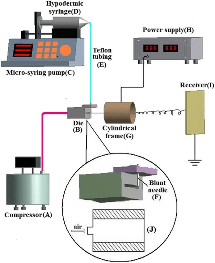
412 Wenxing Zheng et al.
CSBS nanofibers. Insufficient research on the preparation
mechanism and fabrication effect has hindered the pro-
motion and application of CSBS technique.
In this paper, the finite element simulation software
(ANSYS 2020 R2) is used to simulate the CSBS airflow
field, and the distribution of the CSBS airflow field is
studied. The influences of air pressure on the centerline
velocity and the centerline turbulence intensity within
the effective stretching distance are discussed. The effect
of air flow field and electric field on the fabrication and
morphology (fiber diameter and nonwoven porosity) of
CSBS fibers under different air pressures are studied by
theoretical analysis and experiments. In addition, the
relationship between injection speed and CSBS fiber mor-
phology is studied in this work.
2 Experimental
2.1 Materials
Poly(ethylene oxide) (PEO) (Mw = 106 g/mol) was pur- Figure 1: Schematic of CSBS setup (25): (A) compressor, (B) die,
chased from Shanghai Liansheng Chemical Co., Ltd. (C) micro-syringe pump, (D) hypodermic syringe, (E) teflon tubing,
(China). 7 g of PEO powder was added to 93 g of self- (F) blunt needle, (G) cylindrical frame, (H) power supply, (I) receiver,
made distilled water and stirred with a magnetic stirrer (J) cross section of the die.
(X85-2S, Meiyingpu Instrument Co., Ltd., China) at room
temperature for 12 h to prepare 7 wt% PEO solution.
because of the repulsion of the like charges (14,25). CSBS
nanofibers are formed under the combination of airflow
stretching force and electric field force (25).
2.2 Equipment and process
The schematic of the CSBS setup is shown in Figure 1. The 2.3 Experimental details
air compressor (A) generated high-pressure gas and deliv-
ered the gas to the die (B). The micro-syringe pump (C) Two groups of experiments were carried out according to
pushed the polymer solution through the teflon tubing (E) the process parameters listed in Tables 1 and 2. The fabri-
to the blunt needle (length = 38 mm, inner diameter = cation time for each experiment is 80 min. The prepared
0.42 mm, outer diameter = 0.72 mm) (F). The tip of the samples were sputtered with sputter coater (SBC-12, China
blunt needle was facing the center of the die’s outlet. Science Instruments Co., Ltd., China), and then the mor-
The solution extruded from the needle was stretched into phology of the samples was photographed with scanning
a jet by the high-speed airflow ejected from the die. The jet electron microscopy (SEM; S-3400, Hitachi; High-Technolo-
flied through the cylindrical-assisted electrode (G) and gies, Japan). Four SEM photos were taken for each sample.
then formed nanofibers on the receiver (I). The electrode At least 100 measure points were randomly selected for each
(G) was connected to the high-voltage power supply (H). sample; the fiber diameter at each measure point was mea-
The CSBS jet will be charged with the same kind charges sured using ImageJ (National Institutes of Health, USA). The
because of electrostatic induction in the electric field average diameter and diameter standard deviation of each
formed by the electrode. When the charge repulsion is sample were calculated. Ghasemi-Mobarakeh et al. method
greater than the surface tension of the jet, the jet will split (32) was used to measure the porosity of each sample.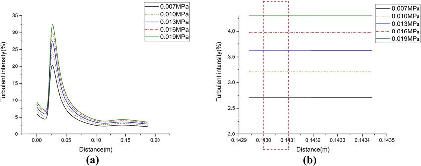
Studies on the fabrication of CSBS nanofibers 413
Table 1: Spinning conditions of different air pressures of the die is symmetrical. To save calculation time, half of
the airflow field was simulated.
Parameter Values The model was generated in SpaceClaim 2020R2, and
Voltage (kV) 7 the airflow field was simulated by FLUENT 2020R2. The
Length of cylinder (cm) 10 k–ε model was used in this paper (18,33). The five air
Diameter of cylinder (cm) 15 pressure values (0.007, 0.01, 0.013, 0.016, and 0.019 MPa)
Needle to cylinder distance (cm) 8 in Table 1 were selected as the inlet air pressures. The outlet
Left face of cylinder to collector 95
air pressure was set to normal pressure. The number of
distance (cm)
Injection speed (mL/h) 0.5
iterations was set to 1,000. The residuals of the five model
Air pressure (MPa) 0.007, 0.01, 0.013, equations of continuity, x-veloctiy, y-velocity, k, and
0.016, 0.019 epsilon were all set to 10−4, and the residuals of the
energy equation was set to 10−6.
Table 2: Spinning conditions of different injection speeds
Parameter Values 3 Results and analysis
Voltage (kV) 10
Length of cylinder (cm) 10
3.1 The effect of air pressure on the
Diameter of cylinder (cm) 15
Needle to cylinder distance (cm) 6 fabrication of CSBS fibers
Left face of cylinder to collector 95
distance (cm) As shown in Figure 3, an increase in air pressure will
Injection speed (mL/h) 0.2, 0.3, 0.4, 0.5, 0.6 cause a smaller fiber diameter. This conclusion can also
Air pressure (MPa) 0.01
be drawn from Figure 4: When the air pressure increased
from 0.007 to 0.019 MPa, the average diameter of CSBS
fibers decreased from 1,662 to 990 nm. In addition, Figure
2.4 Numerical simulation 4 shows that as the air pressure increased from 0.007 to
0.019 MPa, the porosity of the nonwovens decreased from
Part (j) in Figure 1 depicts a cross section of the CSBS die
45.85% to 36%.
used in this article. The left side is the high-pressure gas
Different from traditional SBS and ES, the CSBS fabri-
inlet, and the right side is the gas outlet. Figure 2 shows
cates nanofibers with simultaneous air stretching and
the boundary conditions and the computational domain.
electrostatic force. The following are the explanations
The computational domain was drawn based on the
of the above experimental results from the effect of air-
size of the die. OG (= 2 mm) was the pressure inlet; GF
flow field and electric field on jet.
(= 3 mm), EF (= 3 mm), ED (= 80 mm), and CD (= 40 mm)
were the wall; CB (= 120 mm) and BA (= 105 mm) were the
pressure outlet; OA was the symmetry; ∠BCD = 120°. It
can be seen from part (j) in Figure 1 that the cross section 3.1.1 Effect of airflow field on fiber preparation under
different air pressures
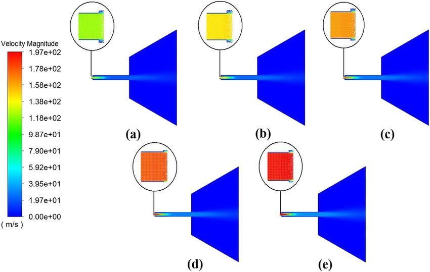
Figure 5 shows the contours of velocity field under dif-
ferent air pressures. The parts selected with oval windows
in Figure 5 are the partial enlarged views of the inlet of
each velocity fields. Figure 5 depicts that an increase in
air pressure will cause an increase in air velocity. As the
tip of the blunt needle in the CSBS setup is always facing
the center of the die’s outlet, the jet fly roughly along OA
(Figure 2). In addition, many articles have studied the
physical quantities on the centerline of the airflow field
to reveal the mechanisms of polymer fiber preparation
(18,33–36). To investigate the impact of CSBS airflow on
Figure 2: Boundary conditions and computational domain. jets and fibers, the centerline velocities of each model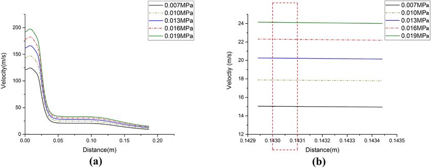
414 Wenxing Zheng et al.
Figure 3: SEM photos of CSBS fibers prepared at the air pressures: (a) 0.007 MPa, (b) 0.01 MPa, (c) 0.013 MPa, (d) 0.016 MPa,
(e) 0.019 MPa.
shows that the greater the air pressure, the greater the
centerline air velocity within the effective stretching dis-
tance. In addition, Chung and Abdalla (37) found the
following relationship between the air force exerted on
the polymer jet (or fiber) and the air velocity:
cρπ 0.815μ0.61Q 0.815(U − VL)1.39 dx
dF = , (1)
VL0.815
where F is the airflow drag force, C is a constant, x is the
fiber/jet axis, μ is the air kinetic viscosity, ρ is the air
density, U is the air velocity, Q is the polymer volume
flow rate, and VL is the final fiber velocity.
From Eq. 1, the faster the air velocity (U), the stronger
the stretching force (F) of the airflow on the jet. In com-
bination with the conclusion in Figure 6b, it can be seen
Figure 4: The relationships between CSBS fiber diameter, CSBS that the higher the air pressure, the faster the airflow
nonwoven porosity, and air pressure. speed, and the greater the air force exerted on the
CSBS jet within the effective stretching distance. Thus,
were extracted and plotted as in Figure 6a. Figure 6a increasing the air pressure can increase the stretching
shows that the centerline velocity increases as the air force of the airflow on the jet to produce thinner CSBS
pressure increases. High-speed gas can only fully stretch fibers.
the jet within the effective stretching distance (100 μm Extract the centerline turbulence intensities of the
from the tip of the needle) (24). When the jet leaves five models and plot these data as in Figure 7a. The tur-
the effective stretching distance, the high-pressure gas bulence intensities in the effective stretching distance in
hardly affects the stretching of the jet. Therefore, the cen- Figure 7a were extracted again and plotted as in Figure 7b.
terline velocities within the effective stretching distance of The part selected with the red window in Figure 7b was
the five models were extracted and plotted as in Figure 6b. the effective stretching distance of the high-speed gas.
The part selected with the red window in Figure 6b is the Figure 7b shows that the greater the air pressure, the
effective stretching distance of the airflow. Figure 6b greater the centerline turbulence intensity within the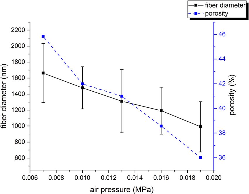
Studies on the fabrication of CSBS nanofibers 415
Figure 5: Contours of velocity field under different air pressures: (a) 0.007 MPa, (b) 0.01 MPa, (c) 0.013 MPa, (d) 0.016 MPa, (e) 0.019 MPa.
Figure 6: Centerline velocities under different air pressures: (a) research distance is [0, 0.187 m], (b) research distance is the effective
stretch distance.
effective stretching distance. The smaller turbulence 3.1.2 Effect of electric field on fiber preparation under
velocity fluctuations are beneficial to prevent the different air pressures
instability in fiber formation (33). Therefore, the greater
the air pressure, the greater the intensity of the turbu- In CSBS system, when the jet enters the electric field
lence, which is more likely to cause the instability in fiber formed by the cylindrical electrode, it will be charged
formation. with the same kind of charges because of electrostatic
Gholipourmalekabadi et al. found that the thinner induction. These like charges will generate charge repul-
the fiber, the lower the porosity of the fiber web (38). sion within the jet. When the charge repulsion exceeds
Consequently, the increase in air pressure causes the the surface tension of the jet, the jet will split and become
CSBS fibers to become thinner, which leads to a decrease thinner (25). In our previous research, the formula for the
in the porosity of the nonwoven. surface charge density of the CSBS jet was obtained: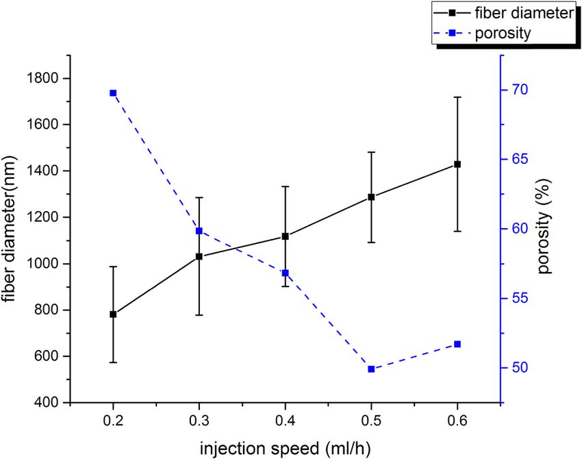
416 Wenxing Zheng et al.
Figure 7: Centerline turbulence intensities under different air pressures: (a) research distance is [0, 0.187 m], (b) research distance is the
effective stretch distance.
Qjet ε0 U0 Denote the denominator of Eq. 2 by x(r1), then:
σjet = = r , (2)
Sjet r1 ln r2 r2
1
x(r1) = r1 ln . (3)
r1
where σjet is the surface charge density of jet; ε0 is the
permittivity of free space; U0 is the voltage; r1 is the radius Take the derivate of Eq. 3 with respect to r1:
of the jet; and r2 is the radius of the cylindrical electrode r2
(39). The permittivity of free space (ε0) is a constant. From x′(r1) = ln − 1. (4)
r1
the parameters in Tables 1 and 2, it can be seen that for a
group of experiments in this article, the voltage (U0) and The unit of the radius of the cylindrical electrode (r2 )
the radius of the cylindrical electrode (r2 ) remain unchanged. is centimeter, as shown in Tables 1 and 2. Bolbasov et al.
Therefore, in Eq. 2, the jet radius (r1) is the only independent found that within the effective stretching distance, the
variable and the jet surface charge density (σjet ) is the only airflow can stretch the diameter of the jet to less than
dependent variable. 1/100 of the inner diameter of the needle (24). The inner
Figure 8: SEM photos of fibers prepared at the injection speeds: (a) 0.2 mL/h, (b) 0.3 mL/h, (c) 0.4 mL/h, (d) 0.5 mL/h, (e) 0.6 mL/h.Studies on the fabrication of CSBS nanofibers 417
diameter of the needle used in this work was 0.42 mm. The reduction in the injection speed will cause the
Therefore, when the jet entered the cavity of electrode, initial volume of the jet to become smaller and thus to
the radius of the jet was in the micron scale. Thus, r2 ≫ e form a thinner jet. Furthermore, Eq. 2 and its analysis
r1
r2 results showed that the thinner the jet is, the more likely
(= 2.71828…) and ln r1
≫ 1. Therefore, x′(r1) is a positive
it is to generate higher surface charge density and thus to
number and Eq. 3 is a monotonous increasing function.
prepare thinner fibers. Therefore, reducing the injection
The decrease in jet radius (r1) will lead to the decrease in
speed can not only reduce the initial jet diameter, but
x(r1) and the increase in σjet . The larger the σjet is, the more
also facilitate the thinning of the jet in the CSBS electric
likely the jet is to split and thin because of charge repul-
field, thereby preparing thinner nanofibers.
sion. Consequently, the smaller the jet diameter, the
For the five experiments in Figure 8, there are two
greater the surface charge density of the jet, which makes
main factors affecting the porosity of CSBS nonwovens:
the jet in the CSBS electric field easier to split because of
fiber diameter and fiber production. The smaller the fiber
the repulsive force among the charges. Increasing the air
diameter, the smaller the porosity of the nonwoven (38).
pressure can make the jet diameter smaller. Thus, the
Too little fiber production will result in greater porosity.
increase in air pressure not only facilitates the stretching
This is because too few fibers cannot take up more space.
and thinning of the jet by the air flow, but also helps the
The preparation time of the samples in this paper is the
jet to become thinner because of charge repulsion. In
same; therefore, the lower the injection speed, the less
summary, increasing the air pressure can reduce the
the fiber production. The result of the competition between
CSBS fiber diameter.
the above two factors determines the porosity of the non-
woven. Therefore, the porosity curve in Figure 9 showed
a decreasing trend first and then increasing with the
3.2 The effect of injection speed on the increase in injection speed.
fabrication of CSBS fiber
Figure 8 depicts the morphologies of CSBS fibers pre-
pared according to Table 2. Figure 9 shows that as 4 Conclusion
the injection speed decreases from 0.6 to 0.2 mL/h, the
average fiber diameter decreases from 1,429 to 781 nm, This paper used computational fluid dynamics technique
and the porosity of the nonwoven decreases first and to study the CSBS airflow field. The simulation results
then increases. The reasons for these results are as showed that as the air pressure increases, the centerline
follows. velocity and the centerline turbulence intensity within
the effective stretching distance increase. The increase
in the centerline velocity will increase the stretching force
of the air-flow on the jet, which will make the jet thinner.
The increase in centerline turbulence intensity will
increase the instability in the formation of CSBS fiber.
The theoretical study of the CSBS electric field revealed
that the surface charge density of the CSBS jet increases
with the decrease in the jet diameter. The increase in air
pressure can not only increase the stretching of the jet by
the air flow, but also make the jet thinner because of the
increase in surface charge density. Increasing the air
pressure can reduce the CSBS fiber diameter and the por-
osity of the nonwoven. The reduction in injection speed
can reduce the initial diameter of the jet and increase the
surface charge density of the jet. Therefore, reducing the
injection speed can make the diameter of the CSBS fiber
smaller. Under the competition of fiber diameter and fiber
production, the porosity of the nonwoven decreases first
Figure 9: The relationships between CSBS fiber diameter, nonwoven and then increases with the increase in the injection
porosity, and injection speed. speed.418 Wenxing Zheng et al.
In this work, a combination of numerical simulation, (5) Lukasova V, Buzgo M, Vocetkova K, Sovkova V, Doupnik M,
theoretical analysis, and experiment is used to study the Himawan E, et al. Needleless electrospun and centrifugal spun
effects of CSBS airflow field and electric field on the fabri- poly-epsilon-caprolactone scaffolds as a carrier for platelets
in tissue engineering applications: a comparative study with
cation of CSBS nanofibers for the first time. The conclu-
hMSCs. Mater Sci Eng C Mater Biol Appl. 2019;97:567–75.
sions of this article provide theoretical and experimental doi: 10.1016/j.msec.2018.12.069.
bases for the controllable preparation of CSBS nano- (6) Aydogdu A, Sumnu G, Sahin S. Fabrication of gallic acid loaded
fibers, which are helpful for the application and promotion hydroxypropyl methylcellulose nanofibers by electrospinning
of CSBS technology in battery, filtration, membrane, etc. technique as active packaging material. Carbohydr Polym.
2019;208:241–50. doi: 10.1016/j.carbpol.2018.12.065.
(7) Cao M, Gu F, Rao C, Fu J, Zhao P. Improving the electrospinning
Acknowledgments: The authors gratefully acknowledge process of fabricating nanofibrous membranes to filter PM2.5.
the National Natural Science Foundation of China (No. Sci Total Environ. 2019;666:1011–21. doi: 10.1016/
51776034) and the Doctoral Special Foundation of Nanyang j.scitotenv.2019.02.207.
Normal University for providing financial support. (8) Tan NPB, Paclijan SS, Ali HNM, Hallazgo CMJS, Lopez CJF,
Ebora YC. Solution blow spinning (SBS) nanofibers for com-
posite air filter masks. ACS Appl Nano Mater.
Funding information: This study was supported by the
2019;2(4):2475–83. doi: 10.1021/acsanm.9b00207.
National Natural Science Foundation of China (51776034) (9) Liu Y, Zhang G, Zhuang X, Li S, Shi L, Kang W, et al. Solution
and the Doctoral Special Foundation of Nanyang Normal blown nylon 6 nanofibrous membrane as scaffold for nano-
University. filtration. Polymers 2019;11(2):364.
(10) Jia K, Zhuang X, Cheng B, Shi S, Shi Z, Zhang B. Solution blown
aligned carbon nanofiber yarn as supercapacitor electrode.
Author contributions: Wenxing Zheng: writing – original
J Mater Sci Mater Electron. 2013;24(12):4769–73.
draft, methodology, project administration; Changwei doi: 10.1007/s10854-013-1472-z.
Shi: investigation, methodology, resources; Yabing Hu: (11) Shi S, Zhuang X, Cheng B, Wang X. Solution blowing of ZnO
writing – original draft, writing – review and editing, nanoflake-encapsulated carbon nanofibers as electrodes for
investigation; Xinhou Wang: methodology, review and supercapacitors. J Mater Chem A. 2013;1(44):13779.
editing, resources; Yiheng Wang: investigation. doi: 10.1039/c3ta13247a.
(12) Zhao Y, Kang W, Li L, Yan G, Wang X, Zhuang X, et al. Solution
blown silicon carbide porous nanofiber membrane as elec-
Conflict of interest: The authors state no conflict of trode materials for supercapacitors. Electrochim Acta.
interest 2016;207:257–65. doi: 10.1016/j.electacta.2016.05.003.
(13) Xu X, Li L, Wang H, Li X, Zhuang X. Solution blown sulfonated
Data availability statement: All data generated or ana- poly(ether ether ketone) nanofiber–Nafion composite mem-
branes for proton exchange membrane fuel cells. RSC Adv.
lyzed during this study are included in this article.
2015;5(7):4934–40. doi: 10.1039/c4ra10898a.
(14) Doshi J, Reneker DH. Electrospinning process and applications
of electrospun fibers. J Electrost 1995;35(2):151–60.
doi: 10.1016/0304-3886(95)00041-8.
(15) Deitzel JM, Kleinmeyer JD, Hirvonen JK, Beck Tan NC.
References Controlled deposition of electrospun poly(ethylene oxide)
fibers. Polymer. 2001;42(19):8163–70. doi: 10.1016/S0032-
(1) Gong W, Li J, Ren G, Lv L. Wound healing and inflammation 3861(01)00336-6.
characteristics of the submicrometric mats prepared from (16) Tan SH, Inai R, Kotaki M, Ramakrishna S. Systematic para-
electrospinning. J Bioact Compat Polym. 2018;34(1):83–96. meter study for ultra-fine fiber fabrication via electrospinning
doi: 10.1177/0883911518813715. process. Polymer. 2005;46(16):6128–34. doi: 10.1016/
(2) Simbara MMO, Santos AR Jr, Andrade AJP, Malmonge SM. j.polymer.2005.05.068.
Comparative study of aligned and nonaligned poly(epsilon- (17) Medeiros ES, Glenn GM, Klamczynski AP, Orts WJ,
caprolactone) fibrous scaffolds prepared by solution blow Mattoso LHC. Solution blow spinning: a new method to pro-
spinning. J Biomed Mater Res B Appl Biomater. duce micro- and nanofibers from polymer solutions. J Appl
2019;107(5):1462–70. doi: 10.1002/jbm.b.34238. Polym Sci. 2009;113(4):2322–30. doi: 10.1002/app.30275.
(3) Oliveira MJCd, Bonan RF, Campos SG, Neves GdA, Menezes RR. (18) Han W, Xie S, Sun X, Wang X, Yan Z. Optimization of airflow
Calcium phosphate submicrometric fibers produced by solu- field via solution blowing for chitosan/PEO nanofiber forma-
tion blow spinning. Mater Res. 2019;22(3):e20180753. tion. Fibers Polym. 2017;18(8):1554–60. doi: 10.1007/s12221-
doi: 10.1590/1980-5373-mr-2018-0753. 017-7213-9.
(4) Akia M, Rodriguez C, Materon L, Gilkerson R, Lozano K. (19) Zhao J, Han W, Chen H, Tu M, Zeng R, Shi Y, et al. Preparation,
Antibacterial activity of polymeric nanofiber membranes structure and crystallinity of chitosan nano-fibers by a solid–
impregnated with Texas sour orange juice. Eur Polym J. liquid phase separation technique. Carbohydr Polym.
2019;115:1–5. doi: 10.1016/j.eurpolymj.2019.03.019. 2011;83(4):1541–6. doi: 10.1016/j.carbpol.2010.10.009.Studies on the fabrication of CSBS nanofibers 419
(20) Padron S, Fuentes A, Caruntu D, Lozano K. Experimental study (29) Shin YM, Hohman MM, Brenner MP, Rutledge GC. Experimental
of nanofiber production through forcespinning. J Appl Phys. characterization of electrospinning: the electrically forced
2013;113(2):024318. doi: 10.1063/1.4769886. jet and instabilities. Polymer. 2001;42(25):9955–67.
(21) Rodriguez-Abreu C, Torres CA, Tiddy GJ. Chromonic liquid doi: 10.1016/S0032-3861(01)00540-7.
crystalline phases of pinacyanol acetate: characterization and (30) Spivak AF, Dzenis YA, Reneker DH. Model of steady state jet in the
use as templates for the preparation of mesoporous silica electrospinning process. Mech Res Commun. 2000;27(1):37.
nanofibers. Langmuir. 2011;27(6):3067–73. doi: 10.1021/ (31) Lauricella M, Succi S, Zussman E, Pisignano D, Yarin AL.
la1048024. Models of polymer solutions in electrified jets and solution
(22) Tutak W, Sarkar S, Lin-Gibson S, Farooque TM, Jyotsnendu G, blowing. Rev Mod Phys. 2020;92(3):035004. doi: 10.1103/
Wang D, et al. The support of bone marrow stromal cell dif- RevModPhys.92.035004.
ferentiation by airbrushed nanofiber scaffolds. Biomaterials. (32) Ghasemi-Mobarakeh L, Semnani D, Morshed M. A novel
2013;34(10):2389–98. doi: 10.1016/ method for porosity measurement of various surface layers of
j.biomaterials.2012.12.020. nanofibers mat using image analysis for tissue engineering
(23) da Silva Parize DD, Foschini MM, de Oliveira JE, applications. J Appl Polym Sci. 2007;106(4):2536–42.
Klamczynski AP, Glenn GM, Marconcini JM, et al. Solution blow doi: 10.1002/app.26949.
spinning: parameters optimization and effects on the proper- (33) Lou H, Han W, Wang X. Numerical study on the solution blowing
ties of nanofibers from poly(lactic acid)/dimethyl carbonate annular jet and its correlation with fiber morphology. Ind Eng
solutions. J Mater Sci. 2016;51(9):4627–38. doi: 10.1007/ Chem Res. 2014;53(7):2830–8. doi: 10.1021/ie4037142.
s10853-016-9778-x. (34) Wang Y, Wang X. Investigation on a new annular melt-blowing
(24) Bolbasov EN, Stankevich KS, Sudarev EA, Bouznik VM, die using numerical simulation. Ind Eng Chem Res.
Kudryavtseva VL, Antonova LV, et al. The investigation of the 2013;52(12):4597–605. doi: 10.1021/ie303338m.
production method influence on the structure and properties (35) Krutka HM, Shambaugh RL, Papavassiliou DV. Analysis of a
of the ferroelectric nonwoven materials based on vinylidene melt-blowing die: comparison of CFD and experiments. Ind Eng
fluoride – tetrafluoroethylene copolymer. Mater Chem Phys. Chem Res. 2002;41(20):5125–38. doi: 10.1021/ie020366f.
2016;182:338–46. doi: 10.1016/j.matchemphys.2016.07.041. (36) Bansal V, Shambaugh RL. On-line determination of diameter
(25) Zheng W, Zheng W, Shi C, Wang X. Cylindrical-electrode- and temperature during melt blowing of polypropylene. Ind
assisted solution blowing for nanofiber spinning. J Appl Polym Eng Chem Res. 1998;37(5):1799–806. doi: 10.1021/
Sci. 2019;136(8):47087. doi: 10.1002/app.47087. ie9709042.
(26) Sinha-Ray S, Sinha-Ray S, Yarin AL, Pourdeyhimi B. (37) Chung T-S, Abdalla S. Mathematical modeling of air-drag
Theoretical and experimental investigation of physical spinning for nonwoven fabrics. Polym Technol Eng.
mechanisms responsible for polymer nanofiber formation in 1985;24(2–3):117–27. doi: 10.1080/03602558508070061.
solution blowing. Polymer. 2015;56:452–63. doi: 10.1016/ (38) Gholipourmalekabadi M, Mozafari M, Bandehpour M,
j.polymer.2014.11.019. Salehi M, Sameni M, Caicedo HH, et al. Optimization of
(27) Hassan MA, Anantharamaiah N, Khan SA, Pourdeyhimi B. nanofibrous silk fibroin scaffold as a delivery system for
Computational fluid dynamics simulations and experiments of bone marrow adherent cells: in vitro and in vivo studies.
meltblown fibrous media: new die designs to enhance fiber Biotechnol Appl Biochem. 2015;62(6):785–94. doi: 10.1002/
attenuation and filtration quality. Ind Eng Chem Res. bab.1324.
2016;55(7):2049–58. doi: 10.1021/acs.iecr.5b04020. (39) Zheng W, Zheng W, Wang X. The effect of electric field on
(28) Han W, Wang X. Modeling melt blowing fiber with different nanofibers preparation in cylindrical-electrode-assisted solu-
polymer constitutive equations. Fibers Polym. tion blowing spinning. Autex Res J. 2020;20(4):497–505.
2016;17(1):74–9.doi:doi: 10.1007/s12221-016-5721-7. doi: 10.2478/aut-2019-0026.You can also read