This product has been discontinued - Cisco UCS C480 ML M5 Purpose Built Server for Deep Learning
←
→
Page content transcription
If your browser does not render page correctly, please read the page content below
Spec Sheet

This product has been discontinued

                   Cisco UCS C480 ML M5
                   Purpose Built Server for
                   Deep Learning

      CISCO SYSTEMS         PUBLICATION HISTORY
      170 WEST TASMAN DR.
      SAN JOSE, CA, 95134   REV A.29   SEPTEMBER 28, 2021
      WWW.CISCO.COM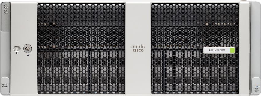
CONTENTS

OVERVIEW . . . . . . . . . . . . . . . . . . . . . . . . . . . . . . . . . . . . . . . . . . . . . . . 5
DETAILED VIEWS . . . . . . . . . . . . . . . . . . . . . . . . . . . . . . . . . . . . . . . . . . . 6
    Chassis Front View . . . . . . . . . . . . . . . . . . . . . . . . . . . . . . . . . . . . . . . . . . . . . . . . . . .6
    UCS C480 ML M5 Server Rear Panel Features . . . . . . . . . . . . . . . . . . . . . . . . . . . . . . . . . .8
BASE SERVER STANDARD CAPABILITIES and FEATURES . . . . . . . . . . . . . . . . . 9
CONFIGURING the SERVER . . . . . . . . . . . . . . . . . . . . . . . . . . . . . . . . . . . 12
    STEP      1 VERIFY BASE SKU . . . . . . . . . . . . . . . . . . . . . . . . . . . . . . . . . . . . . . . . . . . . . 13
    STEP      2 CHOOSE CPU(S) . . . . . . . . . . . . . . . . . . . . . . . . . . . . . . . . . . . . . . . . . . . . . 14
    STEP      3 CHOOSE MEMORY . . . . . . . . . . . . . . . . . . . . . . . . . . . . . . . . . . . . . . . . . . . . 16
    STEP      4 CHOOSE DRIVE MODULES and DRIVES (OPTIONAL) . . . . . . . . . . . . . . . . . . . . . . . 25
    STEP      5 CHOOSE RAID CONFIGURATION . . . . . . . . . . . . . . . . . . . . . . . . . . . . . . . . . . . 29
    STEP      6 CHOOSE PCIe OPTION CARD(S) . . . . . . . . . . . . . . . . . . . . . . . . . . . . . . . . . . . 31
    STEP      7 ORDER OPTIONAL PCIe OPTION CARD ACCESSORIES . . . . . . . . . . . . . . . . . . . . . . 32
    STEP      8 ORDER OPTICAL DRIVE (OPTIONAL) . . . . . . . . . . . . . . . . . . . . . . . . . . . . . . . . 33
    STEP      9 ORDER SECURE DIGITAL CARDS or M.2 DEVICES (OPTIONAL) . . . . . . . . . . . . . . . . 34
    STEP      10 ORDER INTERNAL MICRO-SD CARD MODULE (OPTIONAL) . . . . . . . . . . . . . . . . . . 37
    STEP      11 ORDER POWER SUPPLIES . . . . . . . . . . . . . . . . . . . . . . . . . . . . . . . . . . . . . . . 38
    STEP      12 SELECT AC POWER CORD(s) . . . . . . . . . . . . . . . . . . . . . . . . . . . . . . . . . . . . . 39
    STEP      13 ORDER OPTIONAL CABLE MANAGEMENT ARM . . . . . . . . . . . . . . . . . . . . . . . . . . 42
    STEP      14 ORDER SECURITY DEVICES (OPTIONAL) . . . . . . . . . . . . . . . . . . . . . . . . . . . . . 43
    STEP      15 SELECT MANAGEMENT CONFIGURATION (OPTIONAL) . . . . . . . . . . . . . . . . . . . . 44
    STEP      16 SELECT SERVER BOOT MODE (OPTIONAL) . . . . . . . . . . . . . . . . . . . . . . . . . . . . 45
    STEP      17    CHOOSE OPERATING SYSTEM AND VALUE-ADDED SOFTWARE . . . . . . . . . . . . . 46
    STEP      18 SELECT SERVICE and SUPPORT LEVEL . . . . . . . . . . . . . . . . . . . . . . . . . . . . . . 49
SUPPLEMENTAL MATERIAL . . . . . . . . . . . . . . . . . . . . . . . . . . . . . . . . . . . 55
    CHASSIS . . . . . . . . . . . . . . . . . . . . . . . . . . . . . . . . . . . . . . . . . . . . . . . . . . . . . . . . . 55
    Serviceable Component Locations Inside the Main Chassis . . . . . . . . . . . . . . . . . . . . . . . . 56
    Serviceable Components Inside a CPU Module . . . . . . . . . . . . . . . . . . . . . . . . . . . . . . . . 58
    Serviceable Components Inside an I/O Module . . . . . . . . . . . . . . . . . . . . . . . . . . . . . . . . 59
    CPUs and DIMMs . . . . . . . . . . . . . . . . . . . . . . . . . . . . . . . . . . . . . . . . . . . . . . . . . . . . 60
          Physical Layout . . . . . . . . . . . . . . . . . . . . . . . . . . . . . . . . . . . . . . . . . . . . . . . . 60
          Memory Population Rules . . . . . . . . . . . . . . . . . . . . . . . . . . . . . . . . . . . . . . . . . 61
          Memory Mirroring . . . . . . . . . . . . . . . . . . . . . . . . . . . . . . . . . . . . . . . . . . . . . . 62
    Memory Support for CPU Classes and CPU Modes . . . . . . . . . . . . . . . . . . . . . . . . . . . . . . 63
          For 2nd Generation Intel® Xeon® Scalable Processors: . . . . . . . . . . . . . . . . . . . . . . 63
          For Intel® Xeon® Scalable Processors: . . . . . . . . . . . . . . . . . . . . . . . . . . . . . . . . . 64
          DIMM Population Order . . . . . . . . . . . . . . . . . . . . . . . . . . . . . . . . . . . . . . . . . . . 64
    KVM CABLE . . . . . . . . . . . . . . . . . . . . . . . . . . . . . . . . . . . . . . . . . . . . . . . . . . . . . . . 65
DISCONTINUED EOL PRODUCTS . . . . . . . . . . . . . . . . . . . . . . . . . . . . . . . . 66
TECHNICAL SPECIFICATIONS . . . . . . . . . . . . . . . . . . . . . . . . . . . . . . . . . . 69
    Dimensions and Weight . . . . . . . . . . . . . . . . . . . . . . .        ....   ...   ....    ....   ...   ....    . . 69
    Power Specifications . . . . . . . . . . . . . . . . . . . . . . . .       ....   ...   ....    ....   ...   ....    . . 70
    Environmental Specifications . . . . . . . . . . . . . . . . . . .         ....   ...   ....    ....   ...   ....    . . 71
    Compliance Requirements . . . . . . . . . . . . . . . . . . . . .          ....   ...   ....    ....   ...   ....    . . 72

    2                                                                   Cisco UCS C480 ML Purpose Built Deep Learning Server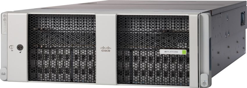
OVERVIEW

OVERVIEW
The Cisco UCS C480 ML M5, a purpose-built Server for Deep Learning, is a four-rack-unit (4RU) server
supporting 2nd Generation Intel® Xeon® Scalable Processors with 8 NVIDIA Tesla V100-32GB Tensor Core GPUs
with NVLink Interconnect. It supports 2933-MHz DDR4 memory, and the new Intel® Optane™ Persistent
Memory (PMEMs). With this combination of features, up to 7.5 TB of memory is possible (using 12 x 128 GB
DDR4 DIMMs and 12 x 512 GB PMEMs), up to 24 small form factor (SFF) hot-swappable2 SAS/SATA SSD/HDD,
up to 6 PCIe NVMe disk drives and upto two internal M.2 drives.

4 PCI Express (PCIe) expansion slots support Cisco UCS C-Series and partner network adapters, with
additional I/O provided by two 10Gbase-T LOM ports and one 1GbE dedicated out-of-band (OOB)
management port. A separate PCIe slot is reserved inside the chassis for a RAID controller card

Figure 1      Cisco UCS C480 ML M5 Purpose Built Deep Learning Server
 Front View

 Rear View

NOTES:
1. A maximum of 3 TB memory is available using 128 GB DIMMs.

Cisco UCS C480 ML Purpose Built Deep Learning Server                                                    5
DETAILED VIEWS
2. Hot-swap replacement means that you do not have to precondition or shut down the component in software before
you remove it.
DETAILED VIEWS
Chassis Front View
Figure 2 is a detailed front view of the Cisco UCS C480 ML M5 Deep Learning Rack Server.
Figure 2 Chassis Front View
1
2
3
4
5
6
7
CPU Module Filler 14
CPU Module 1 13
12
Drive Bay 01
Drive Bay 02
Drive Bay 03
Drive Bay 04
Drive Bay 05
Drive Bay 06
Drive Bay 07
Drive Bay 08
Drive Bay 09
Drive Bay 10
Drive Bay 12
Drive Bay 13
Drive Bay 14
Drive Bay 15
Drive Bay 16
Drive Bay 17
Drive Bay 18
Drive Bay 19
Drive Bay 20
Drive Bay 21
Drive Bay 22
Drive Bay 23
Drive Bay 24
Drive Bay 11
11
UCS
C480 ML
M5
306848
8 9 10
1 Power button/LED 8 Left bay module (drive bays 1 - 8)
■ All 8 bays supports SAS/SATA drives.
■ Bays 1, 2, 7, 8 also support NVMe drives.
6 Cisco UCS C480 ML Purpose Built Deep Learning ServerDETAILED VIEWS
2 Identification button/LED 9 Center bay module (drive bays 9 - 16)
■ All 8 bays supports SAS/SATA drives.
■ Bay 9 also supports NVMe drives.
3 System status LED 10 Right bay module, supports either:
■ Optional DVD drive module
■ Drive bays 17 - 24 (shown)
• All 8 bays supports SAS/SATA drives.
• Bay 17 also supports NVMe drives.
4 Fan status LED 11 KVM console connector (used with a KVM cable that
provides two USBs, one VGA, and one serial
connector)1
5 Temperature status LED 12 Pull-out asset tag
6 Power supply status LED 13 CPU module bay 1
The system must have one CPU module in lower bay
1 to boot.
7 Network link activity LED 14 CPU module bay 2 (blank with filler module)
There must be a blank filler module in upper bay 2
or the system will not boot.
Notes:
1. For more details on the KVM connector, see KVM CABLE on page 65.
Cisco UCS C480 ML Purpose Built Deep Learning Server 7DETAILED VIEWS
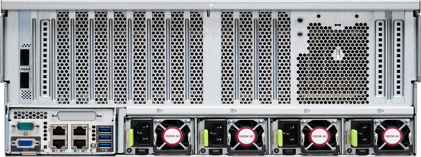
UCS C480 ML M5 Server Rear Panel Features
Figure 3 shows the features of the rear panel.
Figure 3 UCS C480 ML M5 Server Rear Panel
10 10
PCIe 12
PCIe 13
PCIe 14
PCIe 11
1
PSU 1 PSU 2 PSU 3 PSU 4
306849
2
3 4 5 6 7 8 9
1 Serial port COM 1 (DB-9 connector) 7 Rear identification button/LED
2 VGA video port (DB-15 connector) 8 USB 3.0 ports (three)
3 Not used at this time 9 Power supplies 1-4 (hot-swappable,
redundant as 3+1)
4 1-Gb/10-Gb Ethernet ports (LAN1 upper, 10 PCIe slots 11-14 for Network Adapter
LAN2 lower)
The dual LAN ports can support 1 Gbps and
10 Gbps, depending on the link-partner
capability.
5 10/100/1000 Ethernet dedicated _ _
management port (Base-T)
6 Not used at this time _ _
8 Cisco UCS C480 ML Purpose Built Deep Learning ServerBASE SERVER STANDARD CAPABILITIES and FEATURES
BASE SERVER STANDARD CAPABILITIES and FEATURES
Table 1 lists the capabilities and features of the base server. Details about how to configure the server for
a particular feature or capability (for example, number of processors, disk drives, or amount of memory)
are provided in CONFIGURING the SERVER on page 12.
Table 1 Capabilities and Features
Capability/Feature Description
Chassis Four rack unit (4RU) chassis
GPUs 8 NVIDIA Tesla V100-32GB Tensor Core GPUs with NVLink Interconnect
CPU 2nd Generation Intel® Xeon® scalable processor family CPUs.
Chipset Intel® C621 series chipset
Memory 24 DIMM slots and support for Intel® Optane™ Persistent Memory (PMEMs)
Mullti-bit error This server supports multi-bit error protection
protection
Expansion slots There are 4 full-height full-length PCIe expansion slots:
■ Slot Marked 11: CPU1 controlled, Gen-3 x16, FL, FH, NCSI, VIC
■ Slot Marked 12: CPU1 controlled, Gen-3 x16, FL, FH, NCSI, VIC
■ Slot Marked 13: CPU2 controlled, Gen-3 x16, FL, FH, NCSI, VIC
■ Slot Marked 14: CPU2 controlled, Gen-3 x16, FL, FH, NCSI, VIC
NOTE: UCS C480 ML M5 ships with dual CPUs
Storage controller For front-loading drives:
■ UCSC-RAID-M5HD is an internally mounted Cisco 12G Modular RAID
controller with a 4GB cache with a supercap cache backup
(UCSC-SCAP-M5). It is used for controlling the SAS/SATA drives in the front
drive bays. It cannot control NVMe drives in the front drive bays.
■ NVMe drives in the front drive bays are controlled directly from the PCIe
interfaces on the CPUs.
RAID backup The system supports supercap power modules (SCPMs):
■ Front-loading drive bay controller (UCSC-RAID-M5H)—the SCPM mounting
bracket is on the chassis wall near the front RAID controller socket.
DVD drive option Front-loading drive bay 3 can optionally be replaced with a DVD drive
module.
Cisco UCS C480 ML Purpose Built Deep Learning Server 9BASE SERVER STANDARD CAPABILITIES and FEATURES
Table 1 Capabilities and Features (continued)
Capability/Feature Description
Internal storage devices The server can hold up to 24 2.5-inch drives:
■ Front drive bays are divided across three removable drive bay modules.
Each drive bay module has 8 drive bays for a total of 24 front-loading
drive bays.
• All 24 front drive bays support SAS/SATA drives.
• Each of the three drive bay modules has slots that support NVMe SSDs
as well as SAS/SATA drives, for a total of 6 bays that support NVMe
SSDs.
• Drive Bay 1 can have upto 4 NVMe drives while Drive Bay 2 and Drive
Bay3 can have 1 NVMe drive each at designated slots.
SAS and SATA drives are hot-swappable1; NVMe drives are hot-pluggable2
Internal removable ■ A mini-storage module connector on the motherboard supports either:
media
• An M.2 module with two SATA M.2 SSD slots. Mixing different capacity
modules is not supported.
• An SD card module with two SD card slots. Mixing different capacity
SD cards is not Supported
■ One USB 2.0 port on the chassis motherboard.
ACPI This server supports the advanced configuration and power interface (ACPI)
4.0 standard.
Video ■ Resolution up to 1600 x1200, 16 bpp at 60 Hz. Up to 256 MB of video
memory.
Interfaces ■ Rear panel
• One 10/100/1000 dedicated management Ethernet port
• Two 10 Base-T Gbps Ethernet ports
• One RS-232 serial port (DB-9 connector)
• One VGA video port (DB-15 connector)
• Three USB 3.0 connectors
■ Front panel
• One KVM connector (used with the included KVM cable, which
provides two USB, one VGA, and one serial connector)
Power subsystem ■ Power supplies are hot-swappable and rear-accessible. Default to
redundant 3+1
■ 1600 W AC power supply
For more information about your server’s power consumption, use
the power calculator accessible at
http://ucspowercalc.cisco.com
10 Cisco UCS C480 ML Purpose Built Deep Learning ServerBASE SERVER STANDARD CAPABILITIES and FEATURES
Table 1 Capabilities and Features (continued)
Capability/Feature Description
Fans Chassis:
■ 4 fans modules with 2 fans each, hot-swappable
Power supply:
■ Each power supply is equipped with a fan.
Baseboard management Cisco Integrated Management Controller (Cisco IMC) firmware.
Depending on your settings, the Cisco IMC can be accessed through the
10/100/1000 dedicated management ports, the 10 GBase-T LOM ports, or a
Cisco virtual interface card.
Integrated management The built-in Cisco Integrated Management Controller (CIMC) GUI or CLI
processor interface enables you to monitor the server inventory, health, and system
event logs.
Notes:
1. Hot-swappable = No preconditioning of the component is required before removal while the server is powered
on.
2. Hot-pluggable = The component must be shut down in the operating system before removal while the server is
powered on.
Cisco UCS C480 ML Purpose Built Deep Learning Server 11CONFIGURING the SERVER
CONFIGURING the SERVER
Follow these steps to configure the Cisco UCS C480 ML M5 Purpose Built Deep Learning Server
■ STEP 1 VERIFY BASE SKU, page 13
■ STEP 2 CHOOSE CPU(S), page 14
■ STEP 3 CHOOSE MEMORY, page 16
■ STEP 4 CHOOSE DRIVE MODULES and DRIVES (OPTIONAL), page 25
■ STEP 5 CHOOSE RAID CONFIGURATION, page 29
■ STEP 6 CHOOSE PCIe OPTION CARD(S), page 31
■ STEP 7 ORDER OPTIONAL PCIe OPTION CARD ACCESSORIES, page 32
■ STEP 9 ORDER SECURE DIGITAL CARDS or M.2 DEVICES (OPTIONAL), page 34
■ STEP 10 ORDER INTERNAL MICRO-SD CARD MODULE (OPTIONAL), page 37
■ STEP 11 ORDER POWER SUPPLIES, page 38
■ STEP 12 SELECT AC POWER CORD(s), page 39
■ STEP 13 ORDER OPTIONAL CABLE MANAGEMENT ARM, page 42
■ STEP 14 ORDER SECURITY DEVICES (OPTIONAL), page 43
■ STEP 15 SELECT MANAGEMENT CONFIGURATION (OPTIONAL), page 44
■ STEP 16 SELECT SERVER BOOT MODE (OPTIONAL), page 45
■ STEP 17 CHOOSE OPERATING SYSTEM AND VALUE-ADDED SOFTWARE, page 46
12 Cisco UCS C480 ML Purpose Built Deep Learning ServerCONFIGURING the SERVER
STEP 1 VERIFY BASE SKU
Verify the product ID (PID) of the base server as shown in Table 2.
Table 2 PID of the Base C480 ML M5 Rack Server
Product ID (PID) Description
UCSC-C480-M5ML8 Chassis w/8GPU, NoPSU, NoRAID/cable, NoHDDmod, NoCPUmod
The base server:
■ Includes:
— 8 NVIDIA Tesla V100-32GB Tensor Core GPUs with NVLink Interconnect
— Blanking panels for empty drive locations (to maintain cooling air flow)
— Rail kit
■ Does not include:
— CPUs
— DIMMs
— Intel® Optane™ Persistent Memory (PMEMs)
— Power supplies
— Hard disk drives (HDDs)
— Solid-state Drives (SSDs)
— Plug-in PCIe cards
NOTE: Use the steps on the following pages to configure the server with
the components that you want to include.
Cisco UCS C480 ML Purpose Built Deep Learning Server 13CONFIGURING the SERVER
STEP 2 CHOOSE CPU(S)
The standard CPU features are:
■ 2nd Generation Intel® Xeon® scalable processor family CPUs.
■ Intel C621 series chipset
■ Up to 28 cores per processor, for a total of up to 56 cores per server
Select One CPU Module and Two CPUs
Product ID (PID) Description
UCSC-C480-CM UCS C480 ML M5 CPU Module w/o CPU, mem
The available CPUs are listed in Table 3.
Table 3 Available Intel CPUs
Highest DDR4
Clock Cache
Power UPI1Links DIMM Clock
Product ID (PID) Freq Size Cores Processor Type
(W) (GT/s) Support
(GHz) (MB)
(MHz)2
Cisco Recommended Processors3 (2nd Generation Intel® Xeon® Processors)
UCS-CPU-I6248 2.5 150 27.50 20 3 x 10.4 2993 VDI, Oracle, SQL,
UCS-CPU-I5218 2.3 125 22.00 16 3 x 10.4 2666 Virtualization,
Microsoft Azure
Stack, Splunk, Data
Protection
UCS-CPU-I6230 2.1 125 27.50 20 3 x 10.4 2933 Big Data,
Virtualization
UCS-CPU-I5220 2.2 125 24.75 18 3 x 10.4 2666 HCI
8000 Series Processor
UCS-CPU-I8280 2.7 205 38.50 28 3 x 10.4 2933 2nd Gen Intel® Xeon®
6000 Series Processor
UCS-CPU-I6254 3.1 200 24.75 18 3 x 10.4 2933 2nd Gen Intel® Xeon®
UCS-CPU-I6248 2.5 150 27.50 20 3 x 10.4 2993 2nd Gen Intel® Xeon®4
UCS-CPU-I6244 3.6 150 24.75 8 3 x 10.4 2933 2nd Gen Intel® Xeon®
UCS-CPU-I6242 2.8 150 22.00 16 3 x 10.4 2933 2nd Gen Intel® Xeon®
UCS-CPU-I6230 2.1 125 27.50 20 3 x 10.4 2933 2nd Gen Intel® Xeon®
5000 Series Processor
UCS-CPU-I5220 2.2 125 24.75 18 3 x 10.4 2666 2nd Gen Intel® Xeon®
UCS-CPU-I5218 2.3 125 22.00 16 3 x 10.4 2666 2nd Gen Intel® Xeon®
Notes:
1. UPI = Ultra Path Interconnect
14 Cisco UCS C480 ML Purpose Built Deep Learning ServerCONFIGURING the SERVER
2. If higher or lower speed DIMMs are selected than what is shown in the table for a given CPU, the DIMMs will be
clocked at the lowest common denominator of CPU clock and DIMM clock.
3. For details on memory support for processor classes and CPU modes, see Memory Support for CPU Classes and CPU
Modes on page 63.
4. For 2nd Generation Intel® Xeon® Scalable Processor, UCSM 4.0(4b) software release is required.
Approved Configurations
(1) Two-CPU Configuration Only
■ Must choose two identical CPUs from any one of the rows of Table 3 on page 14
■ CPUs 1 and 2 should always will be populated.
NOTE: See CHOOSE MEMORY on page 16 for details on the compatibility of CPUs
and DIMM speeds.
Cisco UCS C480 ML Purpose Built Deep Learning Server 15CONFIGURING the SERVER
STEP 3 CHOOSE MEMORY
The standard memory features are:
■ Clock speed: 2933 MHz depending on CPU type
NOTE: The compatibility of Intel® Xeon® scalable processor family CPUs and 2nd
Generation Intel® Xeon® Scalable CPUs with different DIMM memory speeds and
production servers is as shown below:
DIMM
CPU Family Speed Configuration
(MHz)
Intel Scalable CPUs 2666 2666 MHz DIMMs are supported for all
production servers
2933 2933 MHz DIMMs are not supported for
new production servers
2nd Gen Intel Scalable CPUs 2666 2666 MHz DIMMs are only supported
when upgrading from Intel Scalable
CPUs to 2nd Gen Intel Scalable CPUs
2933 2933 MHz is the only DIMM speed
supported for new production servers
■ Ranks per DIMM: 1, 2, 4, or 8
■ Operational voltage: 1.2 V
■ Registered ECC DDR4 DIMMS (RDIMMs), Load-reduced DIMMs (LRDIMMs) or Intel® Optane™
Persistent Memory (PMEMs).
■ New purchases with 2nd Generation Intel Scalable CPUs need to be configured with
2933-MHz DIMMs.
Memory is organized with six memory channels per CPU, with up to two DIMMs per channel, as
shown in Figure 4.
16 Cisco UCS C480 ML Purpose Built Deep Learning ServerCONFIGURING the SERVER
Figure 4 C480 M5 Memory Organization
Bank 1
Bank 2
Bank 2
Bank 1
A2 A1 G1 G2
Channel A Channel G
B2 B1 H1 H2
Channel B Channel H
C2 C1 J1 J2
Channel C Channel J
CPU 1/3 CPU 2/4
D2 D1 K1 K2
Channel D Channel K
E2 E1 L1 L2
Channel E Channel L
F2 F1 M1 M2
Channel M
Channel F
24 DIMMS
6 memory channels per CPU
2 DIMMs per channel
Cisco UCS C480 ML Purpose Built Deep Learning Server 17CONFIGURING the SERVER
Select DIMMs, PMEM and Memory Mirroring
Select the memory configuration and whether or not you want the memory mirroring option.
The supported memory DIMMs and the mirroring option are listed in Table 4.
Table 4 Available DDR4 DIMMs
Ranks
Product ID (PID) PID Description Voltage
/DIMM
2933-MHz
UCS-ML-128G4RT-H 128 GB DDR4-2933-MHz LRDIMM/4Rx4 (16Gb) 1.2v 1.2 V 4
UCS-ML-X64G4RT-H 64 GB DDR4-2933-MHz LRDIMM/4Rx4 (8Gb) 1.2v 1.2 V 4
UCS-MR-X64G2RT-H 64 GB DDR4-2933-MHz RDIMM/2Rx4 (16Gb) 1.2v 1.2 V 2
UCS-MR-X32G2RT-H 32GB DDR4-2933-MHz RDIMM/2Rx4 (8Gb) 1.2v 1.2 V 2
UCS-MR-X16G1RT-H 16GB DDR4-2933-MHz RDIMM/1Rx4/1.2v 1.2 V 1
Intel® Optane™ Persistent Memory Product
UCS-MP-128GS-A0 Intel® Optane™ Persistent Memory, 128GB, 2666MHz
UCS-MP-256GS-A0 Intel® Optane™ Persistent Memory, 256GB, 2666MHz
Intel® Optane™ Persistent Memory Product Operational Modes
UCS-DCPMM-AD App Direct Mode
UCS-DCPMM-MM Memory Mode
Memory Mirroring Option
N01-MMIRROR Memory mirroring option
NOTE:
■ Based on the Intel tech spec, the below DIMMs be used with the 1st Generation Intel®
Xeon® scalable processor family CPUs and the 2nd Generation Intel® Xeon® scalable
processor family CPUs
UCS-MR-X16G1RT-H
UCS-MR-X32G2RT-H
UCS-ML-X64G4RT-H
■ Based on the Intel tech spec, the below DIMMs can be used only with 2nd Generation
Intel® Xeon® scalable processor family CPUs, not with Intel® Xeon® scalable processor
family CPUs.
UCS-ML-128G4RT-H
UCS-MR-X64G2RT-H
18 Cisco UCS C480 ML Purpose Built Deep Learning ServerCONFIGURING the SERVER DIMM Memory Mirroring When memory mirroring is enabled, the memory subsystem simultaneously writes identical data to two adjacent channels. If a memory read from one of the channels returns incorrect data due to an uncorrectable memory error, the system automatically retrieves the data from the other channel. A transient or soft error in one channel does not affect the mirrored data, and operation continues unless there is a simultaneous error in exactly the same location on a DIMM and its mirrored DIMM. Memory mirroring reduces the amount of memory available to the operating system by 50% because only one of the two populated channels provides data. CPU Configuration Without Memory Mirroring Select from 4, 6, 8, or 12 DIMMs per CPU (DIMMs for all four CPUs must be configured identically). The DIMMs will be placed in each CPU module by the factory as shown in the following tables. #DIMMs CPU 1/3 DIMM Placement in Channels (for identically ranked DIMMs) 4 (A1, B1); (D1, E1) 6 (A1, B1, C1); (D1, E1, F1) 8 (A1, A2, B1, B2); (D1, D2, E1, E2) 12 (A1, A2, B1, B2, C1, C2); (D1, D2, E1, E2, F1, F2) #DIMMs CPU 2/4 DIMM Placement in Channels (for identically ranked DIMMs) 4 (G1, H1); (K1, L1) 6 (G1, H1, J1); (K1, L1, M1) 8 (G1, G2, H1, H2); (K1, K2, L1, L2) 12 (G1, G2, H1, H2, J1, J2); (K1, K2, L1, L2, M1, M2) Cisco UCS C480 ML Purpose Built Deep Learning Server 19
CONFIGURING the SERVER

CPU Configuration With Memory Mirroring
Select from 4, 6, 8, or 12 DIMMs per CPU (DIMMs for all four CPUs must be configured identically). In
addition, the memory mirroring option (N01-MMIRROR) as shown in Table 4 on page 18 must be selected.

The DIMMs will be placed by the factory as shown in the following tables.

                CPU 1/3 DIMM Placement in Channels                   CPU 2/4 DIMM Placement in Channels
 #DIMMs             (for identical ranked DIMMs)                         (for identical ranked DIMMs)

            CPU 1                                              CPU 2
 8            (A1,B1); (D1,E1)                                 (G1, H1); (K1, L1)
 12           (A1, B1, C1); (D1, E1, F1)                       (G1, H1, J1); (K1, L1, M1)
 16           (A1, A2, B1, B2); (D1, D2, E1, E2)               (G1, G2, H1, H2); (K1, K2, L1, L2)
 24           (A1, A2, B1, B2, C1, C2); (D1, D2, E1, E2,       (G1, G2, H1, H2, J1, J2); (K1, K2, L1, L2, M1,
              F1, F2)                                          M2)

                          NOTE: System performance is optimized when the DIMM type and quantity are equal
                          for both CPUs, and when all channels are filled equally across the CPUs in the server.

System Speeds
System speed is dependent on how many DIMMs are populated per channel and the CPU DIMM speed
support. See Table 5 for details.

Table 5 2666-MHz DIMM Memory Speeds with Different Intel® Xeon® Scalable Processors

                                 TSV-
                                               TSV-
DIMM and CPU                     RDIMM                        LRDIMM           RDIMM           LRDIMM
                                               RDIMM
Frequencies         DPC          (8Rx4) -                     (4Rx4) -         (2Rx4) -        (2Rx4) -
                                               (4Rx4) -
(MHz)                            128 GB                       64 GB (MHz)      32 GB (MHz)     32 GB (MHz)
                                               64 GB (MHz)
                                 (MHz)

                                 1.2 V         1.2 V          1.2 V            1.2 V           1.2 V

DIMM = 2666         1DPC         2666          2666           2666             2666            2666
CPU = 2666
                    2DPC         2666          2666           2666             2666            2666

DIMM = 2666         1DPC         2400          2400           2400             2400            2400
CPU = 2400
                    2DPC         2400          2400           2400             2400            2400

DIMM = 2666         1DPC         2133          2133           2133             2133            2133
CPU = 2133
                    2DPC         2133          2133           2133             2133            2133

20                                                         Cisco UCS C480 ML Purpose Built Deep Learning Server
CONFIGURING the SERVER
Table 6 2933-MHz DIMM Memory Speeds with Different 2nd Generation Intel®Xeon® Scalable Processors
DIMM and CPU RDIMM RDIMM
LRDIMM
Frequencies DPC LRDIMM (4Rx4)- (2Rx4) - (2Rx4) -
(4Rx4) -
(MHz) 128 GB (MHz) 64 GB (MHz) 32 GB (MHz)
64 GB (MHz)
1.2 V 1.2 V 1.2 V 1.2 V
DIMM = 2933 1DPC 2933 2933 2933 2933
CPU = 2933
2DPC 2933 2933 2933 2933
DIMM = 2933 1DPC 2666 2666 2666 2666
CPU = 2666
2DPC 2666 2666 2666 2666
DIMM = 2933 1DPC 2400 2400 2400 2400
CPU = 2400
2DPC 2400 2400 2400 2400
DIMM = 2933 1DPC 2133 2133 2133 2133
CPU = 2133
2DPC 2133 2133 2133 2133
Memory Configurations and Modes
DIMM Guidelines
■ System speed is dependent on the CPU DIMM speed support. Refer to Table 4 on page 18 for
DIMM Speeds
■ The C480 M5 server supports four different memory reliability, availability, and
serviceability (RAS) modes:
— Independent Channel Mode
— Mirrored Channel Mode
— Lockstep Channel Mode
— Rank Sparing Mode
NOTE: Mixing of Non-Mirrored and Mirrored mode is not allowed.
■ Do not mix RDIMMs, LRDIMMs, and TSV-RDIMMs.
■ Single-rank DIMMs can be mixed with dual-rank DIMMs in the same channel
■ For best performance, observe the following:
— DIMMs with different timing parameters can be installed on different slots within the
same channel, but only timings that support the slowest DIMM will be applied to all.
As a consequence, faster DIMMs will be operated at timings supported by the slowest
DIMM populated.
Cisco UCS C480 ML Purpose Built Deep Learning Server 21CONFIGURING the SERVER
— When one DIMM is used, it must be populated in DIMM slot 1 (farthest away from the
CPU) of a given channel.
— When single or dual rank DIMMs are populated for 2DPC, always populate the higher
number rank DIMM first (starting from the farthest slot). For a 2DPC example, first
populate with dual rank DIMMs in the DIMM slot 1. Then single-rank DIMMs in the
DIMM 2 slot.
■ DIMMs for all four CPUs must always be configured identically.
■ Cisco memory from previous generation servers (DDR3 and DDR4) is not compatible with UCS
C480 M5 server.
NOTE: System performance is optimized when the DIMM type and quantity are equal
for both CPUs, and when all channels are filled equally across the CPUs in the server.
■ Memory can be configured in any number of DIMMs as pairs, though for optimal
performance, refer to the C480 Memory Guide at Cisco.com.
22 Cisco UCS C480 ML Purpose Built Deep Learning ServerCONFIGURING the SERVER
PMEM Guidelines
■ PMEMs require second generation Intel Xeon Scalable Family processors. First generation Xeon
Scalable processors do not support PMEMs.
■ All installed PMEMs must be the same size. Mixing PMEMs of different capacities is not supported.
■ The use of 1Rx8 DIMMs with PMEMs is not supported.
■ PMEMs and DIMMs must be populated as shown in Table 7 (6 DIMMs per CPU with 2, 4, or 6 PMEMs
per CPU, as shown).
Table 7 2nd Generation Intel® Xeon® Scalable Processor DIMM and PMEM1 Physical Configurations (quad
socket)
DIMM
to
CPU 1/3
PMEM
Count
iMC1 iMC0
Channel 2 Channel 1 Channel 0 Channel 2 Channel 1 Channel 0
F2 F1 E2 E1 D2 D1 C2 C1 B2 B1 A2 A1
6 to 2 DIMM DIMM PMEM DIMM DIMM DIMM PMEM DIMM
6 to 4 DIMM PMEM DIMM PMEM DIMM DIMM PMEM DIMM PMEM DIMM
6 to 6 PMEM DIMM PMEM DIMM PMEM DIMM PMEM DIMM PMEM DIMM PMEM DIMM
DIMM
to CPU 2/4
PMEM
Count
iMC1 iMC0
Channel 2 Channel 1 Channel 0 Channel 2 Channel 1 Channel 0
M2 M1 L2 L1 K2 K1 J2 J1 H2 H1 G2 G1
6 to 2 DIMM DIMM PMEM DIMM DIMM DIMM PMEM DIMM
6 to 4 DIMM PMEM DIMM PMEM DIMM DIMM PMEM DIMM PMEM DIMM
6 to 6 PMEM DIMM PMEM DIMM PMEM DIMM PMEM DIMM PMEM DIMM PMEM DIMM
Notes:
1. All systems must be fully populated with four CPUs when using PMEMs at this time.
■ Two CPUs must be installed in each CPU module when using PMEMs.
■ For Memory Mode, install a minimum 2 PMEMs and 6 DIMMs per CPU
■ For App Direct Mode, install a minimum of 2 PMEMs and 6 DIMMs per CPU
■ When either Memory Mode or Mixed Mode is used, the ratio of DIMM capacity to PMEM
capacity per CPU must be between 1:16 and 1:2, and the recommended ratio is 1:4 for the
best performance. For example, 6x 16GB DIMMs + 2x 256GB PMEMs is a ratio of 1:5.33
(96GB:512GB). In Mixed Mode, the ratio is between memory and only the volatile portion of
the PMEMs. This ratio requirement does not apply to App Direct mode. See Table 8 for
DCCPM memory modes.
Cisco UCS C480 ML Purpose Built Deep Learning Server 23CONFIGURING the SERVER
Table 8 Intel® Optane™ Persistent Memory Modes
Intel® Optane™ Persistent Memory Modes
App Direct Mode: PMEM operates as a solid-state disk storage device. Data is saved and is
non-volatile. Both PMEM and DIMM capacity counts towards CPU tiering
(both PMEM and DIMM capacities count towards the CPU capacity limit)
Memory Mode:1 PMEM operates as a 100% memory module. Data is volatile and DRAM acts
as a cache for PMEMs. Only PMEM capacity counts towards CPU tiering
(only the PMEM capacity counts towards the CPU capacity limit). This is
the factory default mode.
Mix Mode: DRAM as cache. Only PMEM capacity counts towards CPU tiering (only the
PMEM capacity counts towards the CPU capacity limit).
Notes:
1. For Memory Mode, the Intel-recommended DIMM to PMEM capacity ratio in the same CPU socket is from 1:2 to
1:16.
■ For each memory channel with both a PMEM and a DIMM installed, the PMEM is installed in channel
slot 2 (closest) and the DIMM is installed in channel slot 1.
■ To maximize performance, balance all memory channels
■ In configurations with PMEMs installed, memory mirroring is supported, with two restrictions:
■ Mirroring is only enabled on the DIMMs installed in the server; The PMEMs themselves do not
support mirroring.
■ Only App Direct mode is supported. Memory mirroring cannot be enabled when PMEMs are in
Memory Mode or Mixed Mode.
■ Memory sparing is not supported with PMEMs installed
For detailed Intel PMEM configurations, refer to the following link:
Cisco UCS C480 M5 ML Server Installation and Service Guide
24 Cisco UCS C480 ML Purpose Built Deep Learning ServerCONFIGURING the SERVER
STEP 4 CHOOSE DRIVE MODULES and DRIVES (OPTIONAL)
Table 9 Intel® Optane™ Persistent Memory Modes
Intel® Optane™ Persistent Memory Modes
App Direct Mode: PMEM operates as a solid-state disk storage device. Data is saved and is
non-volatile. Both PMEM and DIMM capacity counts towards CPU tiering
(both PMEM and DIMM capacities count towards the CPU capacity limit)
Memory Mode:1 PMEM operates as a 100% memory module. Data is volatile and DRAM acts
as a cache for PMEMs. Only PMEM capacity counts towards CPU tiering
(only the PMEM capacity counts towards the CPU capacity limit). This is
the factory default mode.
Mix Mode: DRAM as cache. Only PMEM capacity counts towards CPU tiering (only the
PMEM capacity counts towards the CPU capacity limit).
Notes:
1. For Memory Mode, the Intel-recommended DIMM to PMEM capacity ratio in the same CPU socket is from 1:2 to
1:16. So if you use a 128 GB DIMM in a channel, you could use a 512 GB PMEM for a 1:4 capacity ratio. if you use
a 32 GB DIMM in a channel, you could use a 512 GB PMEM for a 1:16 capacity ration. There are several other
combinations possible.
Choose Drive Modules
You can choose the following drive modules:
■ Up to three Drive Modules. This is a front-mounting drive cage that accommodates 8 drives as
follows:
— Up to 8 SAS/SATA HDDs or SSDs per module
— Up to four NVMe drives for left module and one NVMe drive each for rest of the
other two modules.
■ Up to three drive modules for 6 x NVMe. This is a front-mounting drive cage accommodating
up to 6 NVMe
The available drive cages are listed in Table 10.
Table 10 Available Drive Modules
Product ID (PID) PID Description
Drive Modules
UCSC-C480-8HDD UCS C480 M5 Drive Module for 8x HDD (standard cage front facing)
Approved Configurations
■ The NVMe drives in the left most Module are restricted to the first two and last two slots only
■ The NVMe drives in the middle and right most Modules are restricted to the first slot only.
Cisco UCS C480 ML Purpose Built Deep Learning Server 25CONFIGURING the SERVER
Choose HDDS and SSDs
The standard hard disk drive (HDD) and solid-state drive (SSD) features are:
■ 2.5-inch small form factor
■ Hot-swappable
■ Sled-mounted
The available drives are listed in Table 11.
Table 11 Supported HDDs and NVMe SSDs
Drive
Product ID (PID) PID Description Capacity
Type
HDDs
HDDs(15K RPM)
UCS-HD900G15K12N 900 GB 12G SAS 15K RPM SFF HDD SAS 900 GB
HDDs(10K RPM)
UCS-HD12TB10K12N 1.2 TB 12G SAS 10K RPM SFF HDD SAS 1.2 TB
UCS-HD18TB10K4KN 1.8 TB 12G SAS 10K RPM SFF HDD (4K) SAS 1.8 TB
HDDs(7K RPM)
UCS-HD2T7K12N 2.0 TB 12G SAS 7.2K RPM SFF HDD SAS 2.0 TB
SAS/SATA SSDs
Enterprise Performance SSDs (High endurance, supports up to 10X or 3X DWPD (drive writes per day))
SAS SSDs
UCS-SD800GK3X-EP 800 GB 2.5in Enterprise Performance 12G SAS SSD(3X SAS 800 GB
endurance)
UCS-SD16TK3X-EP 1.6 TB 2.5in Enterprise Performance 12G SAS SSD(3X SAS 1.6 TB
endurance)
UCS-SD32TK3X-EP 3.2 TB 2.5in Enterprise Performance 12G SAS SSD(3X SAS 3.2 TB
endurance)
Enterprise Value SSDs (Supports up to 1X DWPD (drive writes per day))
SATA SSDs
UCS-SD120GM1X-EV 120 GB 2.5 inch Enterprise Value 6G SATA SSD SATA 120 GB
UCS-SD240GM1X-EV 240 GB 2.5 inch Enterprise Value 6G SATA SSD SATA 240 GB
UCS-SD480GM1X-EV 480 GB 2.5 inch Enterprise Value 6G SATA SSD SATA 480 GB
UCS-SD960GM1X-EV 960 GB 2.5 inch Enterprise Value 6G SATA SSD SATA 960 GB
UCS-SD16TM1X-EV 1.6 TB 2.5 inch Enterprise Value 6G SATA SSD SATA 1.6 TB
UCS-SD19TM1X-EV 1.9 TB 2.5 inch Enterprise Value 6G SATA SSD SATA 1.9 TB
UCS-SD38TM1X-EV 3.8 TB 2.5 inch Enterprise Value 6G SATA SSD SATA 3.8 TB
UCS-SD76TM1X-EV 7.6 TB 2.5 inch Enterprise Value 6G SATA SSD SATA 7.6 TB
26 Cisco UCS C480 ML Purpose Built Deep Learning ServerCONFIGURING the SERVER
Table 11 Supported HDDs and NVMe SSDs (continued)
Drive
Product ID (PID) PID Description Capacity
Type
UCS-SD960GK1X-EV 960GB 2.5 inch Enterprise Value 12G SAS SSD SAS 960 GB
UCS-SD19TK1X-EV 1.9TB 2.5 inch Enterprise Value 12G SAS SSD SAS 1.9 TB
UCS-SD38TK1X-EV 3.8TB 2.5 inch Enterprise Value 12G SAS SSD SAS 3.8 TB
UCS-SD76TK1X-EV 7.6TB 2.5 inch Enterprise Value 12G SAS SSD SAS 7.6 TB
UCS-SD15TK1X-EV 15.3TB 2.5 inch Enterprise Value 12G SAS SSD SAS 15.3 TB
PCIe/NVMe
UCSC-NVMEHW-H6400 6.4 TB 2.5in U.2 HGST SN200 NVMe High Perf. High Endurance NVMe 6.4 TB
UCSC-NVMEHW-H7680 7.7 TB 2.5in U.2 HGST SN200 NVMe High Perf. Value Endurance NVMe 7.7 TB
UCSC-NVMEHW-H800 800 GB 2.5in U.2 HGST SN200 NVMe High Perf. High Endurance NVMe 800 GB
UCSC-NVME2H-I2TBV Cisco 2.5" U.2 2.0TB Intel P4510 NVMe High Perf.Value NVMe 2.0 TB
Endurance
UCSC-NVME2H-I3200 Cisco 2.5" U.2 3.2TB Intel P4610 NVMe High Perf. High NVMe 3.2 TB
Endurance
UCSC-NVME2H-I1600 Cisco 2.5" U.2 1.6TB Intel P4610 NVMe High Perf. High NVMe 1.6 TB
Endurance
UCSC-NVMEHW-I8000 Cisco 2.5" U.2 8TB Intel P4510 NVMe High Perf. Value Endurance NVMe 8.0 TB
UCSC-NVMEXPB-I375* 375GB 2.5in Intel Optane NVMe Extreme Performance SSD NVMe 375 GB
UCSC-NVMEXP-I750* 750GB 2.5in Intel Optane NVMe Extreme Performance NVMe 750 GB
NOTE:
■ Intel and HGST NVMe drives may NOT be mixed anywhere in a C480 ML M5.(*UCSC-NVMEXP-I750 and
UCSC-NVMEXPB-I375 can be mixed for HGST)
■ Cisco uses solid state drives (SSDs) from a number of vendors. All solid state drives are subject to
physical write limits and have varying maximum usage limitation specifications set by the
manufacturer. Cisco will not replace any solid state drives that have exceeded any maximum usage
specifications set by Cisco or the manufacturer, as determined solely by Cisco.
Approved Configurations
Many configurations are possible. Some will be shown here.
(1) Three Drive Modules for 8x HDD
■ Option 1: Fill all three drive modules with all SAS/SATA HDDs or SSDs for a total of 24 drives
■ Option 2: Fill first drive module (left most) with 4 NVMe and 2 SAS/SATA HDDs or SSDs and
the other two with 8 SAS/SATA HDDs/SSDs. You will then have 20 SAS/SATA drives and 4
NVMe drives.
■ Option 3: Fill first drive module (left most) with 4 NVMe and 2 SAS/SATA HDDs or SSDs and
the other two with 7 SAS/SATA HDDs/SSDs and 1 NVMe drive. You will then have 18 SAS/SATA
drives and 6 NVMe drives.
Cisco UCS C480 ML Purpose Built Deep Learning Server 27CONFIGURING the SERVER
Caveats
— You can mix SAS/SATA drives. You can also mix HDD and SSD drives, as long as all the
HDDs are in the same RAID volume and all the SSDs are in the same RAID volume.
— SSDs and HDDs should not be mixed in the same RAID volume.
— You can mix SAS/SATA and NVMe drives in the front facing HDD drive module.
28 Cisco UCS C480 ML Purpose Built Deep Learning ServerCONFIGURING the SERVER
STEP 5 CHOOSE RAID CONFIGURATION
The C480 ML M5 server accommodates any one of the following RAID controllers for internal
drives:
■ Cisco 12G Modular RAID controller with 4GB cache
The C480 ML M5 chassis contains three front drive modules, each housing up to 8 HDD/SSD drives
Cisco can provide factory-configured RAID 0, 1, 5, 6, and 10 systems depending on the RAID
implementation chosen, the RAID controller chosen, and the number of drives ordered.
Factory-configured RAID options are listed at the end of Table 12. Note that RAID levels 50 and
60 are supported on the Cisco 12G SAS Modular 12-port RAID controller, but are not factory
configurable
SSD and HDD requires a RAID controller.
Choose Internal Drive RAID Controller
Choose one internal RAID controller with a desired RAID configuration option from Table 12.
Table 12 Available Internal Drive RAID Options
Product ID (PID) PID Description
RAID Controllers
UCSC-RAID-M5HD Cisco 12G Modular RAID controller with 4GB cache (RAID 0, 1, 5, 6, 10, 50,
60 supported)
■ Plugs into a dedicated PCIe slot on the server motherboard
■ Supports from 1 to 24 internal SAS or SATA drives.
■ Must be ordered with a UCSC-SCAP-M5 supercap cache backup.
■ Factory-configured RAID options: RAID 0, 1, 5, 6, 10 (see the RAID PIDs
section in this table).
■ This RAID controller supports only SAS/SATA drives in the front-facing
HDD card cages.
RAID Configuration
R2XX-RAID0 Factory pre-configured RAID striping option
Enable RAID 0 Setting. Requires a minimum of 1 hard drive.
R2XX-RAID1 Factory pre-configured RAID mirroring option
Enable RAID 1 Setting. Requires exactly 2 drives, with same size, speed,
capacity.
R2XX-RAID5 Factory pre-configured RAID option
Enable RAID 5 Setting. Requires minimum 3 drives of same size, speed,
capacity.
R2XX-RAID6 Factory pre-configured RAID option
Enable RAID 6 Setting. Requires minimum 4 drives of same size, speed,
capacity.
Cisco UCS C480 ML Purpose Built Deep Learning Server 29CONFIGURING the SERVER
Table 12 Available Internal Drive RAID Options (continued)
Product ID (PID) PID Description
R2XX-RAID10 Factory pre-configured RAID option
Enable RAID 10 Setting. Requires an even number of drives (minimum 4
drives) of same size, speed, capacity.
NOTE:
■ No RAID option can be chosen if you have one of the following configurations:
• A mix of SAS and SATA drives
• No drives
Approved Configurations
(1) One RAID controller card for drive module for 8x HDD SAS/SATA drives
■ Choose the UCSC-RAID-M5HD Cisco 12G Modular RAID controller with 4GB cache if you have
SAS/SATA drives mounted in any drive module for 8x HDD.
NOTE: NVMe drives in either of the front facing cage options are controlled directly from
the PCIe interfaces on the CPUs.
Caveats
— You can choose an optional RAID configuration for the internal drive SAS/SATA RAID
controller (RAID 0, 1, 5, 6, or 10), which is pre-configured at the factory. If you do
not choose a RAID configuration, the disks will be configured as a JBOD.
30 Cisco UCS C480 ML Purpose Built Deep Learning ServerCONFIGURING the SERVER
STEP 6 CHOOSE PCIe OPTION CARD(S)
The standard PCIe card offerings are:
■ Virtual Interface Cards (VIC)
■ Network Interface Cards (NICs)
Choose PCIe Option Cards
The available PCIe option cards are listed in Table 13.
Table 13 Available PCIe Option Cards
Form Electrical
Product ID (PID) PID Description
Factor Slot
Virtual Interface Cards (VIC)
25 Gb
UCSC-PCIE-C25Q-04 Cisco UCS VIC 1455 Quad Port 10/25G SFP28 CNA PCIE HHHL x8
100 Gb
UCSC-PCIE-C100-04 Cisco UCS VIC 1495 Dual Port 40/100G QSFP28 CNA PCIe HHHL x16
Network Interface Cards (NICs)
100 Gb NICs
UCSC-PCIE-QS100GF Qlogic QLE45611HLCU single port 100G NIC HHHL x16
UCSC-P-M5D100GF Mellanox CX-5 MCX516A-CDAT 2x100GbE QSFP PCIe NIC HHHL x16
Caveats
■ Cisco VIC card is installed in PCIe slot marked 11, 12, 13, 14
— Only one Cisco VIC can be used for both UCSM management and data traffic in the
C480 ML M5 server
— The Cisco VIC in slot 11 handles management and data traffic.
— Only two VICs total are supported in UCSM mode
■ All PCIe slots are standard-height and require a standard-height mounting bracket on the
PCIe card.
■ To help ensure that your operating system is compatible with the cards you have selected,
please check the Hardware Compatibility List at this URL:
http://www.cisco.com/en/US/products/ps10477/prod_technical_reference_list.htML
NOTE: Mixing 1300 and 1400 series VIC and MLOMs configurations is not supported.
Cisco UCS C480 ML Purpose Built Deep Learning Server 31CONFIGURING the SERVER
STEP 7 ORDER OPTIONAL PCIe OPTION CARD ACCESSORIES
■ For list of supported optics and cables for VIC 1455 and VIC 1497 refer to VIC 1400 series
data sheet at the following links:
— https://www.cisco.com/c/en/us/products/collateral/interfaces-modules/unified-co
mputing-system-adapters/datasheet-c78-741130.html
— https://www.cisco.com/c/en/us/products/collateral/interfaces-modules/unified-co
mputing-system-adapters/datasheet-c78-734727.html
Select
■ NIC Interoperability with Cisco Cables/Optics. (Table 13.0)
Table 13 100G NIC Interoperability with Cables/Optics
Cisco Product ID (PID) UCSC-PCIE-QS100GF UCSC-P-M5D100GF
Cisco Direct Attach Cables (DAC)
QSFP-100G-AOC5M ✓
QSFP-100G-AOC7M ✓
QSFP-100G-AOC10M ✓
QSFP-100G-CU3M ✓
QSFP-100G-CU5M ✓
Cisco Optical Transceivers
QSFP-100G-LR4-S ✓
QSFP-100G-SR4-S ✓
QSFP-40/100-SRBD ✓
a. *: Compiled from testing conducted by Cisco TMG and Vendors.
b. Refer to the these links for additional Connectivity Options.
Intel: Marvell/Qlogic: Mellanox:
Product Guide 41000 series Interoperability Matrix Firmware Release Notes
Speed White Paper 45000 series Interoperability Matrix
32 Cisco UCS C480 ML Purpose Built Deep Learning ServerCONFIGURING the SERVER
STEP 8 ORDER OPTICAL DRIVE (OPTIONAL)
You can order an optional front facing optical drive (DVDRW). If you do, it displaces drive bay
module 3 in the front facing drive cage.
Select Optical Drive
The available optical drive is listed in Table 14.
Table 14 Available Optical Drive
Product ID (PID) PID Description
UCSC-C480-DVD UCS C480 M5 Optional DVD drive
Cisco UCS C480 ML Purpose Built Deep Learning Server 33CONFIGURING the SERVER
STEP 9 ORDER SECURE DIGITAL CARDS or M.2 DEVICES (OPTIONAL)
A mini-storage connector is provided on the motherboard. There are two choices of mini-storage
modular adapters that fit in the connector on the motherboard.
1. Adapter with two SD HC sockets that accommodate up to two SDHC cards
2. Adapter with two M.2 sockets that accommodate up to two M.2 devices
SD Cards and Modular Adapter
The SDHC card ordering information is listed in Table 15.
Table 15 PIDs for Secure Digital High-Capacity Card(s) and Modular Adapter
Product ID (PID) PID Description
UCS-SD-32G-S 32 GB SD Card for UCS servers
UCS-SD-64G-S 64 GB SD Card for UCS servers
UCS-SD-128G 128GB SD Card for UCS servers
UCS-MSTOR-SD1 Modular adapter for SD card
Notes:
1. The SD modular adapter (PID UCS-MSTOR-SD) is auto-included in CCW and is not selectable.
Supported Configurations
(1) Select one or two Cisco secure digital cards
■ Select up to two 32, 64, or 128 GB SD cards
(2) Do not mix SD cards
(3) If you select SDHC cards, you cannot select any M.2 SATA SSD drive.
M.2 SATA Cards and Modular Adapter
Order one or two matching M.2 SATA SSDs (see Table 16) along with a mini storage carrier or a
boot-optimized RAID controller (see Table 17).
NOTE: It is recommended that M.2 SATA SSDs be used as boot-only devices.
34 Cisco UCS C480 ML Purpose Built Deep Learning ServerCONFIGURING the SERVER
Each mini storage carrier or boot-optimized RAID controller can accommodate up to two SATA
M.2 SSDs shown in Table 16.
Table 16 M.2 SATA SSDs
Product ID (PID) PID Description
UCS-M2-240GB 240 GB M.2 SATA SSD
UCS-M2-960GB 960 GB M.2 SATA SSD
Table 17 Mini Storage Carrier/Boot-Optimized RAID Controller
Product ID (PID) PID Description
UCS-MSTOR-M2 Mini Storage Carrier for M.2 SATA (holds up to 2 M.2 SATA SSDs)
UCS-M2-HWRAID Cisco Boot optimized M.2 RAID controller (holds up to 2 M.2 SATA SSDs)
NOTE:
■ The UCS-M2-HWRAID boot-optimized RAID controller supports RAID 1 and JBOD mode
■ The UCS-M2-HWRAID controller is available only with 240 GB and 960 GB M.2 SSDs.
■ (CIMC/UCSM) is supported for configuring of volumes and monitoring of the controller
and installed SATA M.2 drives
■ The minimum version of Cisco IMC and Cisco UCS Manager that support this controller
is 4.0(4b) and later. The name of the controller in the software is MSTOR-RAID
■ The SATA M.2 drives can boot in UEFI mode only. Legacy boot mode is not supported
■ Hot-plug replacement is not supported. The server must be powered off.
■ The boot-optimized RAID controller is not supported when the server is used as a
compute node in HyperFlex configurations
■ Order either the Mini Storage carrier or the Boot-Optimized RAID controller from Table 17.
— Choose the UCS-MSTOR-M2 mini storage carrier for controlling the M.2 SATA drives
with no RAID control.
— Choose the UCS-M2-HWRAID Boot-Optimized RAID controller for hardware RAID
across the two internal SATA M.2 drives. The Boot-Optimized RAID controller holds
up to 2 matching M.2 SATA drives.
■ Order up to two matching M.2 SATA SSDs from Table 16.
NOTE: The Boot-Optimized RAID controller supports VMWare, Windows and Linux
Operating Systems
Cisco UCS C480 ML Purpose Built Deep Learning Server 35CONFIGURING the SERVER
Caveats
■ You cannot mix M.2 SATA SSDs with SD cards.
■ Order either one or two identical M.2 SATA SSDs for the mini-storage carrier or
boot-optimized RAID controller. You cannot mix M.2 SATA SSD capacities.
(4) When ordering two M.2 SATA drives with embedded software RAID, the maximum number of
internal SATA drives supported is six. To support greater than six internal drives, a Cisco 12G
Raid Controller or a Cisco 12G SAS HBA must be ordered
36 Cisco UCS C480 ML Purpose Built Deep Learning ServerCONFIGURING the SERVER
STEP 10 ORDER INTERNAL MICRO-SD CARD MODULE (OPTIONAL)
Order a 32 GB micro-SD card.
The micro-SD card serves as a dedicated local resource for utilities such as HUU. Images can be
pulled from a files hare (NFS/CIFS) and uploaded to the cards for future use.
Table 18 Secure Digital (SD) Card
Product ID (PID) PID Description
UCS-MSD-32G 32GB Micro-SD Card for UCS servers
—
Cisco UCS C480 ML Purpose Built Deep Learning Server 37CONFIGURING the SERVER
STEP 11 ORDER POWER SUPPLIES
The available power supplies are listed in Table 19.
Table 19 Power Supplies
Product ID (PID) PID Description
UCSC-PSU1-1600W Cisco UCS 1600W AC Power Supply for Rack Server
Caveats
— All four power supplies are required
38 Cisco UCS C480 ML Purpose Built Deep Learning ServerCONFIGURING the SERVER
STEP 12 SELECT AC POWER CORD(s)
Select the appropriate AC power cords listed in Table 20. You may select a minimum of no
power cords and a maximum of two power cords. If you select the option R2XX-DMYMPWRCORD,
no power cord is shipped with the server.
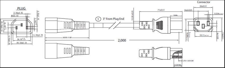
Table 20 Available Power Cords
Product ID (PID) PID Description Images
R2XX-DMYMPWRCORD No power cord (dummy PID to allow for Not applicable
a no power cord option)
CAB-C13-C14-2M CABASY,WIRE,JUMPER CORD, PWR, 2
Meter, C13/C14,10A/250V
CAB-250V-10A-AR Power Cord, SFS, 250V, 10A, Argentina
2500 mm
Cordset rating: 10 A, 250/500 V MAX
Length: 8.2 ft
Plug:
EL 219
(IRAM 2073) Connector:
EL 701
(IEC60320/C13)
186571
CAB-9K10A-AU Power Cord, 250VAC 10A 3112 Plug,
Australia
Cordset rating: 10 A, 250 V/500 V MAX
Length: 2500mm
Connector:
Plug: EL 701C
EL 210 (EN 60320/C15)
186580
(BS 1363A) 13 AMP fuse
CAB-250V-10A-CN AC Power Cord - 250V, 10A - PRC
CAB-9K10A-EU Power Cord, 250VAC 10A CEE 7/7 Plug,
EU
Cordset rating: 10A/16 A, 250 V
Plug: Length: 8 ft 2 in. (2.5 m)
M2511
Connector:
VSCC15
186576
CAB-250V-10A-ID Power Cord, SFS, 250V, 10A, India
OVE
Cordset rating 16A, 250V
Plug:
(2500mm)
EL 208
Connector:
EL 701
187490
Cisco UCS C480 ML Purpose Built Deep Learning Server 39CONFIGURING the SERVER
Table 20 Available Power Cords
Product ID (PID) PID Description Images
CAB-250V-10A-IS Power Cord, SFS, 250V, 10A, Israel
EL-212
16A
250V
Cordset rating 10A, 250V/500V MAX
(2500 mm)
Connector:
Plug: EL 701B
EL 212 (IEC60320/C13)
186574
(SI-32)
CAB-9K10A-IT Power Cord, 250VAC 10A CEI 23-16/VII
Plug, Italy
Cordset rating: 10 A, 250 V
Plug: Length: 8 ft 2 in. (2.5 m) Connector
I/3G C15M
(CEI 23-16) (EN60320/C15 )
186575
CAB-9K10A-SW Power Cord, 250VAC 10A MP232 Plug,
Switzerland
Cordset rating: 10 A, 250 V
Plug: Length: 8 ft. 2 in (2.5 m)
MP232-R
Connector:
IEC 60320 C15
186578
CAB-9K10A-UK Power Cord, 250VAC 10A BS1363 Plug (13
A fuse), UK
Cordset rating: 10 A, 250 V/500 V MAX
Length: 2500mm
Connector:
Plug: EL 701C
EL 210 (EN 60320/C15)
186580
(BS 1363A) 13 AMP fuse
CAB-AC-L620-C13 AC Power Cord, NEMA L6-20 - C13,
2M/6.5ft
CAB-250V-10A-BR Power Cord - 250V, 10A - Brazil
1 76.2 From Plug End
2,133.6 ± 25
CAB-C13-C14-2M-JP Power Cord C13-C14, 2M/6.5ft Japan images not available
PSE mark
CAB-C19-C20-3M-JP Power Cord C19-C20,3M/10ft Japan PSE images not available
mark
CAB-N5K6A-NA Power Cord 200/240V 6A North America images not available
CAB-C13-C14-IN Power Cord Jumper,C13-C14 images not available
Connectors,1.4 Meter Length, India
40 Cisco UCS C480 ML Purpose Built Deep Learning ServerCONFIGURING the SERVER
Table 20 Available Power Cords
Product ID (PID) PID Description Images
CAB-C13-C14-3M-IN Power Cord Jumper, C13-C14 images not available
Connectors, 3 Meter Length, India
Cisco UCS C480 ML Purpose Built Deep Learning Server 41CONFIGURING the SERVER
STEP 13 ORDER OPTIONAL CABLE MANAGEMENT ARM
A cable management arm is available for the tool-less slide rail kit (PID UCSC-RAIL-4U-M5). The
cable management arm attaches to the left and right slide rails at the rear of the server and is
used for cable management. You can order the cable management arm listed in Table 21.
Table 21 Cable Management Arm
Product ID (PID) PID Description
UCSC-CMA-4U-M5 Cable Management Arm for UCS C480 ML
42 Cisco UCS C480 ML Purpose Built Deep Learning ServerCONFIGURING the SERVER
STEP 14 ORDER SECURITY DEVICES (OPTIONAL)
Trusted Platform Module (TPM) is a computer chip (microcontroller) that can securely store
artifacts used to authenticate the platform (server). These artifacts can include passwords,
certificates, or encryption keys. A TPM can also be used to store platform measurements that
help ensure that the platform remains trustworthy. Authentication (ensuring that the platform
can prove that it is what it claims to be) and attestation (a process helping to prove that a
platform is trustworthy and has not been breached) are necessary steps to ensure safer
computing in all environments.
A safety intrusion switch gives a notification of any unauthorized mechanical access into the
server
The security device ordering information listed in Table 22.
Table 22 Security Devices
Product ID (PID) PID Description
UCSX-TPM2-002 Trusted Platform Module 2.0 for UCS servers
UCSX-TPM2-002B Trusted Platform Module 2.0 M5 UCS Servers (FIPS 140-2 Compliant)
UCS-C480-INT-SW UCS C480 Safety Intrusion Switch
NOTE: The module used in this server conforms to TPM v2.0, as defined by the
Trusted Computing Group (TCG).
Cisco UCS C480 ML Purpose Built Deep Learning Server 43CONFIGURING the SERVER
STEP 15 SELECT MANAGEMENT CONFIGURATION (OPTIONAL)
By default, the C480 ML M5 server NIC mode is configured to be Shared LOM Extended. This NIC
mode allows any LOM port or adapter card port to be used to access the Cisco Integrated
Management Controller (CIMC). The Cisco VIC card must be installed in a slot with NCSI support.
To change the default NIC mode to Dedicated, select the UCSC-DLOM-01 PID shown in Table 23.
In Dedicated NIC mode, the CIMC can be accessed only through the dedicated management port.
See UCS C480 ML M5 Server Rear Panel on page 8 for the location of the management port.
To change the default NIC mode to Cisco Card Mode, select the UCSC-CCARD-01 PID shown in
Table 23. In this mode, you can assign an IP address to the CIMC using DHCP and from there you
can fully automate your deployment.
For more details on all the NIC mode settings, see
http://www.cisco.com/c/en/us/td/docs/unified_computing/ucs/c/sw/gui/config/guide/2-0/b_Cisco_UCS_C
-series_GUI_Configuration_Guide_201.pdf
Table 23 Management Configuration Ordering Information
Product ID (PID) PID Description
UCSC-DLOM-01 Dedicated Mode BIOS setting for C-Series Servers
UCSC-CCARD-01 Cisco Card Mode BIOS setting for C-Series Servers
44 Cisco UCS C480 ML Purpose Built Deep Learning ServerCONFIGURING the SERVER
STEP 16 SELECT SERVER BOOT MODE (OPTIONAL)
By default, the C480 ML M5 server will ship with UEFI as the default boot mode. To have a server
shipped with the Legacy BIOS mode (which was standard on M4 and previous generation servers),
select the Legacy BIOS PID
Table 24 Server Boot Mode Ordering Information
Product ID (PID) PID Description
UCSC-LBIOS-01 Legacy Boot Mode BIOS setting for C-Series Servers
Cisco UCS C480 ML Purpose Built Deep Learning Server 45CONFIGURING the SERVER
STEP 17 CHOOSE OPERATING SYSTEM AND VALUE-ADDED SOFTWARE
Several software programs are available. Select as desired from Table 25
Table 25 OSs and vale added software
Product ID (PID) PID Description
Microsoft
MSWS-19-ST16C Windows Server 2019 Standard (16 Cores/2 VMs)
MSWS-19-ST16C-NS Windows Server 2019 Standard (16 Cores/2 VMs) - No Cisco SVC
MSWS-19-DC16C Windows Server 2019 Data Center (16 Cores/Unlimited VMs)
MSWS-19-DC16C-NS Windows Server 2019 DC (16 Cores/Unlim VMs) - No Cisco SVC
Red Hat
RHEL-2S2V-3A Red Hat Enterprise Linux (1-2 CPU,1-2 VN); 3-Yr Support Req
RHEL-2S2V-5A Red Hat Enterprise Linux (1-2 CPU,1-2 VN); 5-Yr Support Req
RHEL-VDC-2SUV-1A RHEL for Virt Datacenters (1-2 CPU, Unlim VN) 1 Yr Supp Req
RHEL-VDC-2SUV-3A RHEL for Virt Datacenters (1-2 CPU, Unlim VN) 3 Yr Supp Req
RHEL-VDC-2SUV-5A RHEL for Virt Datacenters (1-2 CPU, Unlim VN) 5 Yr Supp Req
RHEL-2S2V-1A Red Hat Enterprise Linux (1-2 CPU,1-2 VN); 1-Yr Support Req
RHEL-2S2V-1S Red Hat Enterprise Linux (1-2 CPU,1-2 VN); Prem 1Yr SnS Reqd
RHEL-2S2V-3S Red Hat Enterprise Linux (1-2 CPU,1-2 VN); Prem 3Yr SnS Reqd
RHEL-2S-HA-1S RHEL High Availability (1-2 CPU); Premium 1-yr SnS Reqd
RHEL-2S-HA-3S RHEL High Availability (1-2 CPU); Premium 3-yr SnS Reqd
RHEL-2S-RS-1S RHEL Resilent Storage (1-2 CPU); Premium 1-yr SnS Reqd
RHEL-2S-RS-3S RHEL Resilent Storage (1-2 CPU); Premium 3-yr SnS Reqd
RHEL-2S-SFS-1S RHEL Scalable File System (1-2 CPU); Premium 1-yr SnS Reqd
RHEL-2S-SFS-3S RHEL Scalable File System (1-2 CPU); Premium 3-yr SnS Reqd
RHEL-VDC-2SUV-1S RHEL for Virt Datacenters (1-2 CPU, Unlim VN) 1 Yr SnS Reqd
RHEL-VDC-2SUV-3S RHEL for Virt Datacenters (1-2 CPU, Unlim VN) 3 Yr SnS Reqd
VMware
VMW-VSP-STD-1A VMware vSphere 7 Std (1 CPU, 32 Core) 1-yr, Support Required
VMW-VSP-STD-3A VMware vSphere 7 Std (1 CPU, 32 Core) 3-yr, Support Required
VMW-VSP-STD-5A VMware vSphere 7 Std (1 CPU, 32 Core) 5-yr, Support Required
46 Cisco UCS C480 ML Purpose Built Deep Learning ServerCONFIGURING the SERVER Table 25 OSs and vale added software Product ID (PID) PID Description VMW-VSP-EPL-3A VMware vSphere 7 Ent Plus (1 CPU, 32 Core) 1Yr, Support Reqd VMW-VSP-EPL-1A VMware vSphere 7 Ent Plus (1 CPU, 32 Core) 3Yr, Support Reqd VMW-VSP-EPL-5A VMware vSphere 7 Ent Plus (1 CPU, 32 Core) 5Yr, Support Reqd SUSE SLES-2S2V-1A SUSE Linux Enterprise Svr (1-2 CPU,1-2 VM); 1-Yr Support Req SLES-2SUV-1A SUSE Linux Enterprise Svr (1-2 CPU,Unl VM); 1-Yr Support Req SLES-2S2V-3A SUSE Linux Enterprise Svr (1-2 CPU,1-2 VM); 3-Yr Support Req SLES-2SUV-3A SUSE Linux Enterprise Svr (1-2 CPU,Unl VM); 3-Yr Support Req SLES-2S2V-5A SUSE Linux Enterprise Svr (1-2 CPU,1-2 VM); 5-Yr Support Req SLES-2SUV-5A SUSE Linux Enterprise Svr (1-2 CPU,Unl VM); 5-Yr Support Req SLES-2S2V-1S SUSE Linux Enterprise Svr (1-2 CPU,1-2 VM); Prio 1-Yr SnS SLES-2SUV-1S SUSE Linux Enterprise Svr (1-2 CPU,Unl VM); Prio 1-Yr SnS SLES-2S2V-3S SUSE Linux Enterprise Svr (1-2 CPU,1-2 VM); Prio 3-Yr SnS SLES-2SUV-3S SUSE Linux Enterprise Svr (1-2 CPU,Unl VM); Prio 3-Yr SnS SLES-2S2V-5S SUSE Linux Enterprise Svr (1-2 CPU,1-2 VM); Prio 5-Yr SnS SLES-2SUV-5S SUSE Linux Enterprise Svr (1-2 CPU,Unl VM); Prio 5-Yr SnS SLES-2S-HA-1S SUSE Linux High Availability Ext (1-2 CPU); 1yr SnS SLES-2S-HA-3S SUSE Linux High Availability Ext (1-2 CPU); 3yr SnS SLES-2S-HA-5S SUSE Linux High Availability Ext (1-2 CPU); 5yr SnS SLES-2S-GC-1S SUSE Linux GEO Clustering for HA (1-2 CPU); 1yr Sns SLES-2S-GC-3S SUSE Linux GEO Clustering for HA (1-2 CPU); 3yr SnS SLES-2S-GC-5S SUSE Linux GEO Clustering for HA (1-2 CPU); 5yr SnS SLES-2S-LP-1S SUSE Linux Live Patching Add-on (1-2 CPU); 1yr SnS Required SLES-2S-LP-3S SUSE Linux Live Patching Add-on (1-2 CPU); 3yr SnS Required SLES-2S-LP-1A SUSE Linux Live Patching Add-on (1-2 CPU); 1yr Support Req SLES-2S-LP-3A SUSE Linux Live Patching Add-on (1-2 CPU); 3yr Support Req Nvidia NGC Support Cisco UCS C480 ML Purpose Built Deep Learning Server 47
CONFIGURING the SERVER

Table 25 OSs and vale added software

 Product ID (PID)          PID Description

 NV-NGC-S-1YR               Nvidia NGC Support Services For C480 ML; 1 Year

 NV-NGC-S-3YR               Nvidia NGC Support Services For C480 ML; 3 Year

 NV-NGC-S-R-1YR             Nvidia NGC Support Services For C480 ML; 1 Year, RENEW

48                                                  Cisco UCS C480 ML Purpose Built Deep Learning Server
You can also read