TRISKELION - USER MANUAL - CMC Rescue
←
→
Page content transcription
If your browser does not render page correctly, please read the page content below
TRISKELION™

                             USER MANUAL
Standards                                  NFPA 1983 (2017 ED)
                                           General Use

                                           EN
                                           FR
  2797
                                           DE
Compliant with European                    IT
Regulation (EU) 2016/425                   ES
CEN/TS 16415:2013 Type B                   NO
for 2 Person Use and                       SE
EN 795:2012 Type B
For Single Person Use                      Find the latest version of this
                                           Manual, available translations,
                                           and the EU Declaration of
                                           Conformity at cmcpro.com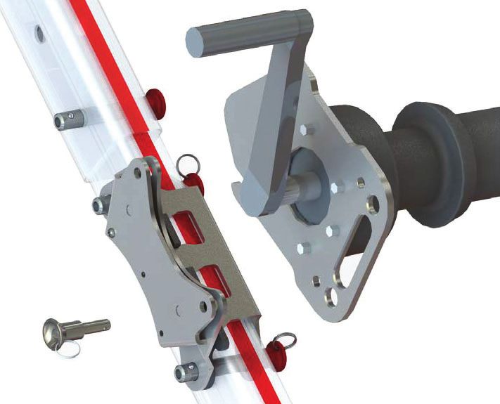
USER MANUAL

                                                                                                           TRISKELION

CMC CUSTOMER SUPPORT
UNITED STATES
Phone: 800-235-5741                         Fax: 800-235-8951
INTERNATIONAL
Phone: 805-562-9120                         Fax: 805-562-9870
E-MAIL:                 info@cmcpro.com
WEBSITE:                cmcpro.com
MAILING ADDRESS:
6740 Cortona Drive, Goleta, CA 93117 USA                                  Triskelion Serial Number:

RESPONSIBILITY                                                          CMC WARRANTY STATEMENT
Activities involving the use of this device are inherently              If your CMC product has a defect due to workmanship
dangerous. The User shall assume all risks and responsibilities         or materials, please contact CMC Customer Support for
for any damage, injury or death, which may occur during or              warranty information and service. CMC’s warranty does not
following the incorrect use of this equipment. This document            cover damages caused by improper care, improper use,
must be provided to the User by the retailer in the respective          DOWHUDWLRQV DQG PRGL¿FDWLRQV DFFLGHQWDO GDPDJH RU WKH
country’s language and must be kept with the equipment while            natural breakdown of material over extended use and time.
it is in use. Observe relevant national regulations.                    All repair work shall be performed by CMC or a trained,
                                                                        DXWKRUL]HG 6HUYLFH $JHQW $OO RWKHU ZRUN RU PRGL¿FDWLRQV
These instructions explain the correct use of your equipment.
                                                                        void the warranty and releases CMC and the manufacturer
The warning symbols inform you of some potential dangers
                                                                        from all liability and responsibility. CMC encourages users
related to the use of your equipment, but it is impossible to
                                                                        to maintain an inspection record to document relevant
describe them all. You are responsible for heeding each
                                                                        information as suggested in the table at the end of this
warning and using your equipment correctly. Any misuse of
                                                                        manual.
this equipment will create additional dangers. Contact CMC
LI \RX KDYH DQ\ TXHVWLRQV RU GLI¿FXOW\ XQGHUVWDQGLQJ WKHVH
instructions. Check cmcpro.com for updates and additional
information.
Before using this equipment, you must:
•     Read and understand these instructions and warnings.
•     2EWDLQVSHFL¿FWUDLQLQJDQGFRPSHWHQF\LQLWVSURSHUXVH
•     Familiarize yourself with its capabilities and limitations.
•     Understand and accept the risks involved.
•     Have a rescue plan in place to deal with any emergencies
      that could arise during use of the device.
•     %HPHGLFDOO\¿WIRUWKHVHDFWLYLWLHV
•     Be capable of controlling your own security and emergency
      situations.
Check equipment before and after use.

CE Compliance Information                                                             Ferno Australia Pty Ltd
                                                                                      11 Johnstone Road
CE Certifying Organization                                                            Brendale, Queensland 4500, Australia
BSI Group The Netherlands B.V. (NB 2797)                                              +61 7 3881 4999 / info@ferno.com.au
Say Building, John M Keynesplein 9
                                                                                      00510-V3 / NOV 2020
1066 EP, Amsterdam, Netherlands
Compliant with European Regulation (EU) 2016/425                                      Ferno-Washington Italia S.r.l.
CEN/TS 16415:2013 Type B for 2 Person Use and                                         via B. Zallone, n. 26, 40066
EN 795:2012 Type B for Single Person Use                                              Pieve di Cento, Bologna, Italy
                                                                                      +39.051.6860028         234-3468-01

                                                                    2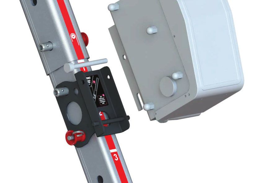
USER MANUAL

                                                                                              TRISKELION

SAFETY INFORMATION

                       WARNING                                                         NOTICE
 Warning safety alerts indicate a potentially hazardous          Notices emphasize important, but not hazard-related
 situation that, if not avoided, could result in injury or       information. Failure to follow Notices could result in
 death.                                                          product or property damage.

GLOSSARY                                                         TRACEABILITY & MARKINGS
Competent Person
A person designated by their employer who                        Leg Markings and Labels
through training and knowledge, is capable of
identifying defects, evaluating and addressing                                 Pulley over Leg
existing and potential hazards, and who has
authority to take corrective action with regards to
such hazards.                                                                  Serial Number Label provides the
                                                                               SURGXFW¶VXQLTXHLGHQWL¿FDWLRQQXPEHU
Hobble Strap                                                                   and date of manufacture.
Used to hobble the legs of a tripod together to
prevent the legs from spreading apart.
                                                                               Numeric Labels on each leg provides
Main Line                                                                      a visual representation of the height
The primary line supporting the load.                                          setting of each leg.

MBS
Minimum Breaking Strength
NFPA
National Fire Protection Association
Portable Anchor
                                                                 &HUWL¿FDWLRQ/DEHOSURYLGHVDTXLFNUHIHUHQFHWRWKH
A manufactured device with rigid legs designed to
                                                                 Testing Standards, Minimum Breaking Strengths and the
support human loads. Also known as a tripod or
                                                                 Manufactuer’s details.
DQDUWL¿FLDOKLJKGLUHFWLRQDO $+'
PPE
Personal Protective Equipment
Resultant Force                                                  Carry Bag Marking
The single linear directional force equal to the
sum of all forces applied to an object.
Safety / Belay / Backup Line
A secondary rope or system used to support the
load should the Main Line fail.                                  Store the Triskelion in the Carry Bag, with head facing in
                                                                 the same direction as illustrated.
WLL
Working Load Limit - determined by dividing
the minimum breaking strength (MBS) by a
designated factor of safety.
Tether Line
A line used to prevent an object from falling over
an edge.

                                                             3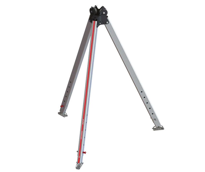
USER MANUAL

                                                                                                                        TRISKELION

ABOUT THE CMC TRISKELION
FEATURES
                                                                                                                                          w
1.      One-piece fabricated steel head
                                                                                                    q
2.      Two stainless steel pulleys to redirect rope or cables up                                                                 e
        to 13 mm diameter
3.      Three tie-off points for rigging or stabilization
                                                                                                                                            r
4.      Three side-plate anchor points
5.      Rectangular, adjustable legs with quick-action ball lock
        leg pins
6.      Pivoting feet with aggressive non-slip tread and                                                                t
        integrated spike
7.      Adjustable Hobble Strap with Cobra Quick Release
        buckle (not illustrated)
8.      Carry Bag (not illustrated)
                                                                                                                                y

SPECIFICATIONS
                                                    7ULSRGIRUVHFXULQJRQHRUWZRSHUVRQVVLPXOWDQHRXVO\IRUDFFHVVRUZRUNLQFRQ¿QHGVSDFHV
 DESIGNATION
                                                    where a fall from height may occur. Not intended for lifting equipment.
 WEIGHT                                             32 kg (70 lb) Tripod only

 LEG HOLE SPACING                                   100 mm (3.94”)
                                                    MINIMUM HEIGHT                                       MAXIMUM HEIGHT
 WORKING HEIGHT
                                                    1700 mm (67”) *                                      3050 mm (120”) *
 to underside of head
 OVERALL HEIGHT                                     1930 mm (76”) *                                      3270 mm (128.7”) *
 FOOT PRINT
 Inside Ø of feet                                   1580 mm (62.2”) *                                    2820 mm (111”) *
 Outside Ø of feet                                  1930 mm (76”) *                                      3170 mm (124.8”) *

 WLLg (attached direct to head)                                                                360 kg (792 lb*)
          g
 WLL (attached to leg over pulley)                                                              220 kg (484 lb*)
 MBS (attached direct to head)                                                                       36kN
 MBS (attached to leg over pulley)                                                                   22kN
                                                    Tripod:               Steel, aluminum and stainless steel
                                                    Foot Tread:           Thermoplastic Elastomer
 MATERIALS
                                                    Leg Stoppers:         Polyurethane
                                                    Pulley Spacers:       Acetal
                                                    1 x Triskelion
                                                    1 x Hobble Strap
 IN THE BOX                                         1 x Carry Bag
                                                    1 x User Manual

* Dimensions and weights are approximate only
g
     The nominated working load limits are recommended by the manufacturer and calculated by a safety factor of 10:1 to the MBS. Users should determine an
     appropriate safety ratio that is within their applicable regulations and local protocols.

                                                                                4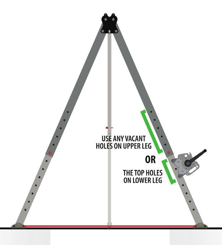
USER MANUAL

                                                                                                         TRISKELION

INSTRUCTIONS FOR USE
                                                                                                   WARNING
GENERAL SAFETY INSTRUCTIONS
                                                                              •   The User assumes all responsibility for any non-
1.   The Triskelion and associated hardware must always                           standard use of the device or the components
     be tethered to prevent it from falling over edges.                           being used with the device.
2.   The Triskelion may become unstable or topple if used                     •   Danger may arise and functionality may be
     without an assessment of the resultant force and                             compromised by combining other items of
     direction. Additional rigging may be required to ensure                      equipment in conjunction with the Triskelion during
     complete stabilization.                                                      use.
3.   Ensure the User is in good physical and mental health,                   •   Do not use the Triskelion if any parts are missing
     and is trained and competent in the use of the Triskelion.                   or have not been properly maintained.
     The User should have all relevant PPE for the job prior
     to starting any work at height. PPE may include, but
     is not limited to, a harness, shock-absorbing lanyard,
     helmet, gloves and appropriate footwear.
                                                                                                   NOTICE
4.   A rescue plan is mandatory when working at height or
     LQDFRQ¿QHGVSDFH(QVXUHWKHZKROHWHDPLVIDPLOLDU               Operating in, or exposing the Triskelion to extreme
     with the rescue plan and their roles.                                temperatures, caustic chemicals, hazardous
5.   Do not modify or tamper with the Triskelion in any way.              environments or excessively rough handling or
     Doing so will void the Warranty.                                     treatment may cause damage to the device.

6.   The Triskelion may only be repaired or serviced by
     CMC or a trained, authorized Service Agent.
7.   When the Triskelion is used as part of a fall arrest
     system, the User must be equipped with a means                      COMPATIBLE PRODUCTS
     of limiting the maximum dynamic forces exerted to
     themselves during the arrest of a fall to a maximum of              The use of the Triskelion is limited to combinations of
     6kN (1350 lbf).                                                     approved and registered components only. Examples
                                                                         include:
8.   A shock-absorbing lanyard assembly should be
     secured to an anchorage point which is at a level that              1.       (TXLSPHQWFHUWL¿HGWR(11)3$DQGRWKHULQGXVWU\
     will result in the minimum free fall and the least total fall                standards.
     distance consistent with the wearer’s ability to carry out
     work tasks.                                                         2.       Approved and tested components by CMC.
9.   When making a connection to any point on a harness                  Other combinations and components not meeting these
     which cannot be seen by the wearer of the harness, the              standards should not be used as they may compromise
     connection should either be made before putting the                 the safe operation of the system.
     harness on, or it should be connected or checked for
                                                                         Further information regarding portable anchors can be
     security by a competent person.
                                                                         found in NFPA 1500, NFPA 1858 and NFPA 1983.
10. To avoid a pendulum effect during a fall, the maximum
    angle from the anchor point at the top of the Triskelion
    must not exceed 15° either side of the center of the
    anchor point.
11. For safety, the Triskelion should be carried and set up
    by two or more people.
12. If any part of an assembly is to be exposed to chemicals
    such as caustic materials or hazardous atmospheres,
    the User should consult CMC or the manufacturer to
    determine whether the part is suitable for continued
    use.

                                                                     5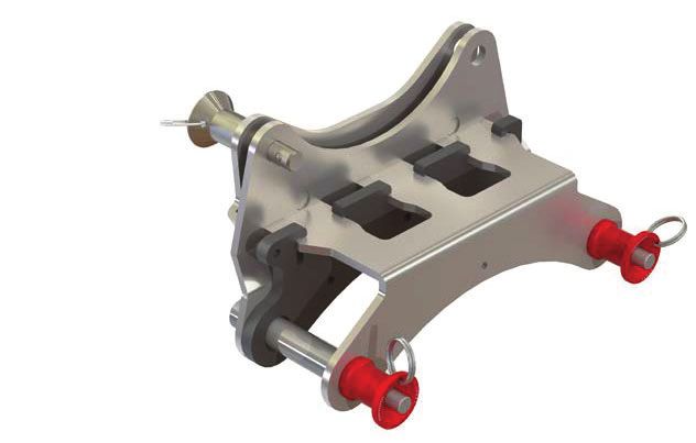
USER MANUAL

                                                                                               TRISKELION

INSTRUCTIONS FOR USE
BEFORE EACH USE                                                         Pre-Use Inspection Checklist
User Inspection                                                      'RWKHOHJV¿WWRJHWKHUDQGH[WHQGVPRRWKO\"
The Triskelion should be inspected by a competent person             $UHWKHOHJVEHQWFUDFNHGRUGHIRUPHG"
before and after each use to ensure it functions correctly
and all components are free of damage. The User should               Are all fasteners (eg. bolts, pins) present and
also refer to the User Manual as required. A Pre-Use                 VHFXUHO\WLJKWHQHG"
Inspection Checklist is provided as a guide, which may be            Is retaining hardware on pins present and in
used in conjunction with your approved agency protocols.             JRRGFRQGLWLRQ"

Refer any signs of deterioration to an authorized person for         Are the pins in good condition and functioning
a decision on the safety and serviceability of the Triskelion.       FRUUHFWO\"
If in doubt, tag it out!                                             Are the pulleys in good condition and functioning
                                                                     FRUUHFWO\"

For periodic inspections, refer to the Inspections                   Do any plastic parts show signs of wear or
                                                                     FKHPLFDOGDPDJH"
section on page 13.
                                                                     Are the feet and lashing holes showing signs of
                                                                     GHIRUPDWLRQGDPDJHRUVKDUSHGJHV"

                       WARNING                                       Is the adjustable Hobble Strap present and in
                                                                     JRRGFRQGLWLRQ"
 Do not assemble the Triskelion over an open hole. Erect
 the Triskelion away from voids and edges, then move
 it to the required location once the Triskelion legs have
 been extended and locked into place.

SETTING UP THE TRISKELION
                                                                                                                       Figure 1
For safety, the Triskelion should be carried and set up by
at least two or more people.
1.   Check the Surface
     •   0DNHVXUHWKHVXEVWUDWHRUÀRRUEHORZWKH
         Triskelion feet can sustain the anticipated loads
         (Figure 1).
     •   %HZDUHRIVRIWJURXQGDQGXQVXSSRUWHGÀRRUV
         Manage these accordingly.
     •   The Triskelion has pivoting feet with spiked
         tips and rubberized soles to adapt to different
         surfaces.
     •   Use the Hobble Strap to prevent the legs from
         spreading apart.
     •   Ground Stakes are available as an optional
         accessory if individual feet require additional
         stabilization (refer to page 15).

                                                                 6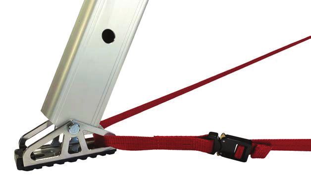
USER MANUAL

                                                                                                   TRISKELION

INSTRUCTIONS FOR USE                                                                                                Figure 2

SETTING UP THE TRISKELION                       (CONTINUED)

2.   Assemble the Triskelion
     •   Stand the Triskelion upright and extend individual legs
         to proper height. To extend legs:
         a.   Depress the pin release button at the head of the
              pin and remove it from the leg (Figure 2).              Depress and hold pin release button
                                                                         down to retract pin from leg
         b.   Extend or retract legs to achieve the desired
              height. Once height is achieved, align holes and
              re-insert leg pins.                                                                                   Figure 3

     •    Double check all leg pins are locked in place, and the
          Triskelion is at the correct height.
     •    Move the Triskelion to the desired location and splay
          legs over area to required spread width.
     •    Thread the Hobble Strap through each Triskelion
          foot, then clip the two halves together (Figure 3).
          Tighten the loose end to remove any slack in the
          strap. This prevents the legs from splaying outwards.

                                                                                                                    Figure 4

                      WARNING
 Adjusting legs can be a pinch point hazard. Hold the
 upper leg section rather than the lower leg, and keep
 ¿QJHUVRXWRIOHJKROHV

3.   Keep the Triskelion head level
     • 2QÀDWVXUIDFHVDOOWKHOHJVZLOOEHWKHVDPH
        length.                                                                                                     Figure 5
     • On uneven surfaces the legs can be different
        lengths.
     • Adjust the length of one or more legs so the
        Triskelion head is level and directly over the
        opening or work area.
         Figure 4: Flat surface
         Figure 5: Sloping surface
         Figure 6: Floor of different heights

                                                                                                                    Figure 6

                                                                  7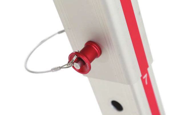
USER MANUAL

                                                                            TRISKELION

INSTRUCTIONS FOR USE                                                                 Figure 7

TRISKELION AS A HIGH ANCHOR
Example: With a self-retracting lifeline

•       Attach the self-retracting lifeline to an anchor point on the
        Triskelion head (Figure 7 and 8).
•       Keep the load within the Triskelion legs (Figure 7 and 8).
•       Do not operate a load outside of the Triskelion legs
        (Figure 9).

                          WARNING
    •   Operating outside of the Triskelion legs can create
        a sideways swing and topple the tripod. Keep the
        load within the legs.
    •   For safety, verify there is adequate distance and                            Figure 8

        clear space below the area of operation so that in
        the event of a fall, the User will not come in contact
        with the ground or other obstacles.

                                                                                     Figure 9

                                                                        8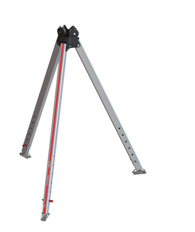
USER MANUAL

                                                                                            TRISKELION

INSTRUCTIONS FOR USE                                                                                     Figure 10

ATTACHING ACCESSORIES TO LEGS
Approved accessories which are designed to be attached
WRWKH7ULVNHOLRQOHJKDYHVSHFL¿FDUHDVZKHUHWKH\PD\EH
installed. Refer to instructions for individual accessories to
determine where each may be attached.

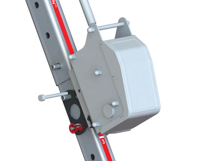
Attaching the Triskelion-LokHead
Winch Adapter
The Triskelion-LokHead Winch Adapter is an optional
accessory and is designed to enable the Harken LokHead
Winch to be mounted to and operated with the Triskelion
(refer to page 15).
To attach the winch and winch adapter:
1.   Determine where the LokHead Winch will be
     positioned on the Triskelion leg (Figure 10).
     •   Ensure a leg with a pulley is selected. These legs
         are marked with a Pulley over Leg symbol
         on the red leg labels.
     •   Determine if the LokHead Winch handle is to be
         oriented on the left or right side, and on the inside
                                                                     Secures through
                                                                               ro
                                                                                ough
                                                                                  g winch                   Figure 11
         or outside of the leg.
2.   Remove the two red pins from the adapter and
     position it on the leg, aligning the pin holes in the
     adapter with corresponding holes in the Triskelion leg.
     Re-insert the red pins to secure the adapter in place.
     •   If attaching the adapter to the upper leg, the                     Spacer
                                                                                er
         spacer is not required and should be removed                                            Sec
                                                                                                 Se  ures
                                                                                                     ure
                                                                                                 Securess tto
                                                                                                            o lleg
         before securing the adapter to the leg (Figure 11).
     •   If attaching the adapter to the upper holes of the
         lower leg, the spacer is required to create a snug
         ¿WDQGVKRXOGEH¿[HGLQSODFHEHIRUHWKHDGDSWHU                                               Figure 12
         is secured to the leg (Figure 11).
         7R¿WWKHVSDFHURULHQWDWHWKHWZRKROHVLQWKH
         spacer with the pin holes in the adapter. Insert
         the spacer from the adapter’s underside. Fit
         the slider tongues through the wider part of
         the rectangular slots, then slide it across to the
         opposite side until the spacer engages with an
         audible click.
3.   Remove the silver lock pin from the winch adapter,
     then insert the LokHead Winch into the adapter slot,
     ensuring cutout ALQWKHZLQFKSODWH¿WVDURXQGWKH
     welded pin   B   inside the adapter slot (Figure 12).
4.   Re-insert the silver lock pin, using the lower of the
     two available holes to secure the winch to the adapter
     (Figure 12).

                                                                 9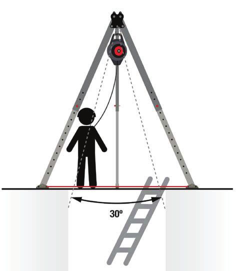
USER MANUAL

                                                                     TRISKELION

INSTRUCTIONS FOR USE                                                         Figure 13

Attaching the Triskelion-Salalift II
Winch Adapter
The Triskelion-Salalift II Winch Adapter is an optional
accessory and is designed to enable the 3M DBI/SALA
Salalift II Winch to be mounted to and used with the
Triskelion (refer to page 15).
To attach the winch and winch adapter:
1.   Attach the adaptor to the lower Triskelion leg using the
     top two holes nearest the upper leg (Figure 13).
     •   Ensure a leg with a pulley is selected. These legs
         are marked with a Pulley over Leg symbol
         on the red leg labels.
                                                                             Figure 14
2.   Remove the two red pins from the adapter and
     position it on the leg, aligning the pin holes in the
     adapter with corresponding holes in the Triskelion leg.
     Re-insert the red pins to secure the adapter in place
     (Figure 14).
3.   5HPRYHWKHORFNSLQIURPWKHGHYLFHWKHQ¿WWKH
     Winch over the adapter bracket ensuring cutout A in
     WKHZLQFKSODWH¿WVDURXQGWKHZHOGHGSLQB on the
     adapter (Figure 15).                                                    Figure 15

4.   Re-insert the lock pin to secure the winch to the
     adapter (Figure 16).

                                                                             Figure 16

                                                                10
USER MANUAL
TRISKELION
INSTRUCTIONS FOR USE
Figure 18
TRISKELION AS A CHANGE OF
DIRECTION
To use the Triskelion as a change of direction:
• Use the integrated pulleys in the Triskelion head
OR
• Attach a pulley to an anchor point on the Triskelion
head.
The resultant force bisects the rope/cable coming into and
out of a pulley (Figure 17).
Figure 17
Figure 19
The resultant force (indicated by the dashed line) must be
kept within the triangle formed by the feet when there is no
stabilization rigging‡ as it can topple the Triskelion.
This is achieved by keeping the haul line parallel with the
legs and inside of the Hobble Strap.
Safety / Belay / Backup Line omitted from Figures 18, 19
and 20 for clarity.
Figure 18: Progress capture pulley system Figure 20
Figure 19: Winch
Figure 20: Pulling away from the legs without
stabilization rigging
‡
There are three stabilization attachment points on the
Triskelion head for advanced users. Stabilization rigging is
not covered in this manual.
11USER MANUAL
TRISKELION
INSTRUCTIONS FOR USE Figure 21
TWO POINTS OF CONTACT
Two points of contact with the User is needed for
height safety:
1. A primary means of support and
2. A backup system.
Options for the primary means of support include a ladder,
winch or pulley system.
A backup system is used if the primary means of support
fails. Examples of a backup system include a self-
retracting lifeline or winch.
• Figure 21:
Primary: Ladder
Backup: Self-retracting Lifeline
• Figure 22: Figure 22
Primary: Winch
Backup: Self-retracting Lifeline
12USER MANUAL
TRISKELION
INSPECTIONS MAINTENANCE
To maintain the safety and serviceability of this product, Cleaning the Triskelion
regular inspections must be performed.
1. Wash the Triskelion with warm water and a soft
User Inspection detergent.
Each User should be trained in the safe use and inspection 2. Rinse with clean water.
of the Triskelion. The Triskelion should be inspected by 3. Air-dry the unpacked Triskelion in a dry, shaded and
a competent person before and after each use to ensure well-ventilated area. Do not use additional heat sources
it functions correctly and that all components are safe to or blowers to dry the Triskelion.
use. 4. Avoid contact with chemicals, oils, solvents and other
aggressive corrosive materials or agents.
A Pre-Use Inspection Checklist is provided as a guide on 5. Once the Triskelion is dry, store it in the Carry Bag.
page 6 of this manual. It may be used in conjunction with
your approved organization protocols.
STORAGE
Refer any signs of deterioration to a competent, authorized The Carry Bag is designed for optimal balance when
person for a decision on the safety and serviceability of carrying the Triskelion. To ensure proper balance, position
the product. If in doubt, tag it out! the Triskelion head according to the placement graphic
located on the inside of the bag.
Periodic Inspections
• A periodic inspection should be conducted every 6
months and at least yearly by a competent person.
Inspection frequencies can be increased depending
Store the Triskelion in the Carry Bag in a clean, dry area
on how often the device is used, environmental
away from direct sunlight, chemicals and corrosive elements.
conditions, legislation and/or organizational protocols.
A Periodic Inspection Checklist is provided on page
14. TRANSPORT
• If any part of the system is to be exposed to harsh To avoid damage during transport, the Triskelion should be
chemicals or hazardous atmospheres, the User packed in its bag or an appropriate container or box.
should consult with CMC or the manufacturer to
determine whether the part is suitable for continued SERVICING & PARTS
use.
Repair work on the Triskelion may only be carried out by
• Periodic inspections should be recorded in the CMC or a trained, authorized Service Agent. Any other
product’s Inspection and Maintenance Log. A sample UHSDLUZRUNRUPRGL¿FDWLRQVWRWKHSURGXFWZLOOYRLGLWV
log is provided on page 15. warranty.
• It is recommended to tag the device with the date of For service or repairs, please contact your local CMC
its next inspection. Distributor or CMC Customer Support.
Spare Parts
WARNING
The spare parts listed below may be replaced by the User
• Remove the Triskelion from service if it has been RU3URGXFW2ZQHU$OORWKHUSDUWVPXVWEH¿WWHGE\&0&RU
used to arrest a fall, or if you have any doubt about a trained, authorized Service Agent.
the Triskelion’s condition for safe use. Do not use
it again until it has been inspected by CMC or PART # DESCRIPTION
an appropriately trained, authorized person and 760002 Carry Bag
ZULWWHQFRQ¿UPDWLRQLVSURYLGHG 760003 Tripod Leg Label
• The Triskelion has been engineered and tested 760004 Triskelion Foot
using the original components as supplied. Never 760005 Hobble Strap
replace pins, bolts or other supplied components
760006 Ball Lock Leg Pin
with non-genuine parts.
760007 Pulley Detent Pin
760008 Lanyard
760009 Leg Strap
760013 Winch Adapter Spacer
13USER MANUAL
TRISKELION
PERIODIC INSPECTION CHECKLIST
INSPECTION ACTION IF DAMAGED
$Q\GDPDJHVXFKDVFUDFNVGHQWVRUJRXJLQJ" Remove from service for further inspection
'ROHJVHFWLRQVH[WHQGDQGUHWUDFWVPRRWKO\" and replacement.
Do leg pin holes show obvious damage, gouging, elongation or deep Remove from service if deep indents greater
LQGHQWDWLRQVRQWKHSLQDUHD" than 0.02” / 0.5mm are present.
'ROHJSLQVRSHUDWHVPRRWKO\"'RWKHEDOOORFNVUHOHDVHZKHQWKH
LEGS and Replace pins if not operating smoothly.
EXWWRQLVGHSUHVVHG"
LEG PINS
Inspect the lanyard attaching leg pins to the legs for damage. Replace the lanyard if damaged.
Do the leg stoppers prevent the inner leg tube from separating
Remove from service for repair if damaged.
FRPSOHWHO\IURPWKHRXWHUWXEH"
Contact CMC Customer Service if serial
,VWKHVHULDOQXPEHUODEHOSUHVHQWDQGOHJLEOH"
numbers are not legible.
,VWKHOHJODEHOZLWKORDGUDWLQJLQIRUPDWLRQSUHVHQWDQGOHJLEOH" Replace if illegible.
,VWKHKHDGVHFXUHO\DWWDFKHGWRWKH7ULVNHOLRQOHJV" Remove from service for further inspection if
$UHDOOIDVWHQHUVSUHVHQWDQGWLJKWHQHG" loose.
Return to CMC or a trained, authorized
Inspect entire head for damage and indentations. Normal wear and tear
Service Agent for repair or replacement if
is acceptable.
obvious damage is present.
Do the pulleys rotate freely with no binding or resistance on the pulley
HEAD EHDULQJV"
Do not use if damaged.
Inspect the grooves of the pulley. Is there damage or sharp edges within
WKHVKHDYH"
$UHWKHGHWHQWSLQVVHFXUHGWRWKHKHDG"'RWKH\RSHUDWHDQGLQVHUW
Replace the detent pin if missing or damaged.
HDVLO\LQWRWKHKROHV"
/XEULFDWHZLWKD7HÀRQEDVHGVSUD\OXEULFDQW
'RGHWHQWSLQVVKRZVLJQVRIUXVWRUGDPDJH"
if pins are rusting.
Inspect the feet and lashing holes for deformation, damage and sharp
FEET edges. Replace the foot if it is damaged.
,VWKHUXEEHUWUHDGVKRZLQJVLJQVRIGDPDJH"
Are there signs of cuts or tears in the webbing, abrasion damage,
excessive stretching, deterioration due to rotting, mildew or ultraviolet
H[SRVXUH"
HOBBLE
,VZHEELQJVWLWFKLQJEURNHQRUFXW"$UHWKHUHDQ\ZRUQWKUHDGVRU Replace if damaged.
STRAP
damaged / weakened threads due to contact with heat, corrosives,
VROYHQWVRUPLOGHZ"
,VWKHEXFNOHGLVWRUWHGFUDFNHGRUSK\VLFDOO\GDPDJHG"
14USER MANUAL
TRISKELION
TRISKELION ACCESSORIES
FOOT STEP KIT GROUND STAKE TRISKELION- TRISKELION-
(2 Steps) KIT (3 Stakes) LOKHEAD WINCH SALALIFT II
The Foot Step mounts to The Ground Stake is ADAPTER WINCH ADAPTER
the lower section of the designed to secure the The adapter enables the The adapter enables the 3M
Triskelion leg. It is an aid that Triskelion foot. It is ideal for Harken LokHead Winch to DBI/SALA Salalift II Winch
enables the operator to reach soft-ground applications be mounted and used with to be mounted and used with
the Triskelion head to adjust such as grass. the Triskelion. the Triskelion.
rigging after setup.
Part # 760016 Part # 760012 Part # 760014
Part # 760015
SAMPLE INSPECTION & MAINTENANCE LOG
SUPPLIER
DETAILS
DESIGNATION
MODEL/ITEM # MANUFACTURE DATE
SERIAL # PURCHASE DATE
COMMISSIONED DATE AGENCY / UNIT
NEXT
DATE INSPECTION OR MAINTENANCE & ACTION TAKEN PARTS REPLACED SIGNATURE
INSPECTION
15USER MANUAL
TRISKELION
FRANÇAIS INFORMATION SUR LA
SÉCURITÉ
RESPONSABILITÉ
Les activités inhérentes à l’utilisation de cet appareil sont
intrinsèquement dangereuses. L’Utilisateur assume tous
AVERTISSEMENT
les risques et responsabilités pour tout dommage, blessure
ou mort, qui pourrait survenir pendant ou à la suite d’une Les alertes de sécurité indiquent une situation
mauvaise utilisation de cet équipement. Ce document doit potentiellement dangereuse qui, si elle n’est pas évitée,
être fourni à l’utilisateur par le revendeur dans la langue pourrait entraîner des blessures ou la mort.
du pays concerné et doit être conservé avec l’équipement
pendant son utilisation. Respectez les réglementations
nationales en vigueur.
Ces instructions expliquent l’utilisation correcte de AVIS
votre équipement. Les symboles d’avertissement vous
informent de certains dangers potentiels liés à l’utilisation Les avis mettent l’accent sur des informations
de votre équipement, mais il est impossible de tous les importantes, mais pas sur les dangers. Le non-respect
décrire. Vous êtes responsable de tenir compte de chaque des avis peut entraîner des dégradations du matériel ou
avertissement et d’utiliser correctement votre équipement. de biens annexes
Toute mauvaise utilisation de cet équipement créera des
dangers supplémentaires. Contactez CMC si vous avez des
TXHVWLRQVRXVLYRXVDYH]GHVGLI¿FXOWpVjFRPSUHQGUHFHV
instructions. Consultez notre site : cmcpro.com pour obtenir
GLOSSAIRE
Personne compétente
des mises à jour et des informations supplémentaires.
Une personne désignée par son employeur qui, grâce à la
Avant d’utiliser cet équipement, vous devez:
IRUPDWLRQHWjVHVFRQQDLVVDQFHVHVWFDSDEOHG¶LGHQWL¿HU
• Lire et comprendre ces instructions et avertissements. les défauts, d’évaluer et de traiter les dangers existants
• Acquérir une formation et des compétences et potentiels, et qui a le pouvoir de prendre des mesures
VSpFL¿TXHVSRXUVRQXWLOLVDWLRQFRUUHFWH correctives à l’égard de ces dangers.
• Vous familiariser avec ses capacités et ses limites. Sangle Hobble
• Comprendre et accepter les risques encourus. Utilisé pour entraver les jambes d’un trépied pour empêcher
• $YRLUXQSODQGHVDXYHWDJHSUpDODEOHPHQWpWDEOLD¿Q les jambes de s’écarter.
de faire face à toute urgence qui pourrait survenir lors
de l’utilisation de l’appareil. Ligne principale
• Être médicalement apte à ces activités. La ligne principale supportant la charge.
• Etre capable de contrôler votre propre sécurité et les MBS (Minimum Breaking Strength)
situations d’urgence. Force de rupture minimale
9pUL¿H]O¶pTXLSHPHQWDYDQWHWDSUqVXWLOLVDWLRQ NFPA
Voir page 2 pour les informations de conformité CE. Association nationale de protection contre les incendies
Ancrage portable
DÉCLARATION DE GARANTIE Un appareil fabriqué avec des pieds rigides conçu pour
Si votre produit CMC présente un défaut de fabrication ou supporter des charges humaines. Aussi connu sous le nom
de matériaux, veuillez contacter l’assistance clientèle CMC de trépied ou point haut.
pour obtenir des informations sur la garantie et le service.
EPI
La garantie de CMC ne couvre pas les dommages causés
Équipement de protection individuelle
par un entretien inapproprié, une utilisation inappropriée,
GHV DOWpUDWLRQV HW GHV PRGL¿FDWLRQV GHV GRPPDJHV Résultante
accidentels ou la l’usure naturelle du matériel pendant une Force directionnelle linéaire unique égale à la somme de
utilisation et une durée prolongées. Tous les travaux de toutes les forces appliquées à un objet.
réparation doivent être effectués par CMC ou un agent d’un
Sécurité / Assurance / Ligne de secours
VHUYLFHTXDOL¿pHWUHFRQQXSDU&0&7RXWDXWUHWUDYDLORX
Une corde ou un système secondaire utilisé pour supporter
PRGL¿FDWLRQDQQXOHODJDUDQWLHHWGpJDJH&0&HWOHIDEULFDQW
la charge en cas de défaillance de la ligne principale.
de toute engagement et responsabilité. CMC encourage les
XWLOLVDWHXUVjFRQVHUYHUXQUHJLVWUHG¶LQVSHFWLRQD¿QG¶DYRLU WLL (Working Load Limit)
un suivi du matériel, comme suggéré dans le tableau à la Limite de charge de travail - déterminée en divisant la
¿QGHFHPDQXHO résistance à la rupture minimale (MBS) par un facteur de
16USER MANUAL
TRISKELION
sécurité désigné.
MODE D’EMPLOI
Ligne de Vie
Une ligne utilisée pour empêcher un objet de tomber.
INSTRUCTIONS GÉNÉRALES DE
SÉCURITÉ
TRAÇABILITÉ ET MARQUAGES 1. Le Triskelion et le matériel associé doivent toujours
être attachés pour éviter qu’il ne tombe sur les bords.
Marquages et étiquettes des pieds 2. Le Triskelion peut devenir instable ou basculer s’il est
utilisé sans évaluation de la force et de la direction
Voir page 3 pour les symboles. résultantes. Un gréement supplémentaire peut être
1. Poulie sur les pieds nécessaire pour assurer une stabilisation complète.
2. L’étiquette du numéro de série fournit le numéro
3. Assurez-vous que l’utilisateur est en bonne santé
G¶LGHQWL¿FDWLRQ XQLTXH GX SURGXLW HW OD GDWH GH
physique et mentale et qu’il est formé et compétent
fabrication.
dans l’utilisation du Triskelion. L’utilisateur doit disposer
3. Les étiquettes numériques sur chaque pied fournissent
de tous les EPI nécessaires pour le travail avant
une représentation visuelle du réglage de la hauteur de
de commencer tout travail en hauteur. L’EPI peut
chaque jambe.
inclure, mais sans s’y limiter, un harnais, une longe
4. /¶pWLTXHWWHGHFHUWL¿FDWLRQIRXUQLWXQHUpIpUHQFHUDSLGH
amortissante, un casque, des gants et des chaussures
aux normes d’essai, aux résistances minimales à la
appropriées.
rupture et aux détails du fabricant.
4. Un plan de sauvetage est obligatoire lors de travaux en
Marquage du sac de transport KDXWHXURXGDQVXQHVSDFHFRQ¿Qp$VVXUH]YRXVTXH
Rangez le Triskelion dans le sac de transport, la tête tournée toute l’équipe connaît le plan de sauvetage et ses rôles.
dans la même direction que celle illustrée. 5. 1HPRGL¿H]RXQ¶DOWpUH]HQDXFXQHIDoRQOH7ULVNHOLRQ
Cela annulera la garantie.
6. Le Triskelion ne peut être réparé ou entretenu que par
À PROPOS DU CMC TRISKELION &0& RX XQ DJHQW GH VHUYLFH TXDOL¿p HW UHFRQQX SDU
CMC.
FONCTIONNALITÉS 7. Lorsque le Triskelion est utilisé dans le cadre d’un
système antichute, l’utilisateur doit être équipé d’un
1. Tête en acier monobloc
moyen permettant de limiter les forces dynamiques
2. Deux poulies en acier inoxydable pour rediriger la
maximales exercées sur lui-même lors de l’arrêt d’une
corde ou les câbles jusqu’à 13 mm de diamètre
chute à un maximum de 6 kN (1350 lbf).
3. Trois points d’arrimage pour le gréement ou la
stabilisation 8. 8QH ORQJH DPRUWLVVDQWH GRLW rWUH ¿[pH j XQ SRLQW
4. Trois points d’ancrage de plaque latérale d’ancrage qui se trouve à un niveau qui entraînera la
5. Pieds rectangulaires réglables avec goupilles de chute libre minimale et la distance de chute la moins
verrouillage à bille à action rapide totale compatible avec la capacité de l’utilisateur à
6. Pieds pivotants avec bande de roulement antidérapante effectuer des tâches.
agressive et crampon intégré 9. Lors de la connexion à un point quelconque d’un harnais
7. Sangle de retenue des pieds réglable avec boucle qui ne peut pas être vu par le porteur du harnais, la
Cobra Quick Release (non illustrée) connexion doit être soit faite avant de mettre le harnais,
8. Sac de transport (non illustré) VRLWHOOHGRLWrWUHFRQQHFWpHRXYpUL¿pHSRXUODVpFXULWp
par une personne compétente.
Voir page 4 pour le tableau des spécifications et l’illustration. 10. Pour éviter un effet de pendule lors d’une chute,
l’angle maximum depuis le point d’ancrage en haut du
Triskelion ne doit pas dépasser 15 ° de part et d’autre
du centre du point d’ancrage.
11. Pour des raisons de sécurité, le Triskelion doit être
porté et installé par minimum deux personnes.
12. Si une partie d’un assemblage doit être exposée à des
produits chimiques tels que des matières caustiques
ou des atmosphères dangereuses, l’utilisateur doit
consulter CMC ou le fabricant pour déterminer si la
pièce est adaptée à une utilisation continue.
17USER MANUAL
TRISKELION
AVERTISSEMENT AVIS
• L’Utilisateur assume toute responsabilité pour Utiliser ou exposer le Triskelion à des températures
toute utilisation non standard de l’appareil ou des extrêmes, à des produits chimiques caustiques, à des
composants utilisés avec l’appareil. environnements dangereux ou à une manipulation ou
un traitement excessivement brutal peut endommager
• Un danger peut survenir et la fonctionnalité
l’appareil.
peut être compromise en combinant d’autres
équipements avec le Triskelion pendant l’utilisation.
• N’utilisez pas le Triskelion si des pièces manquent ASSEMBLEZ LE TRISKELION
ou n’ont pas été correctement entretenues.
MISE EN PLACE DU TRISKELION
PRODUITS COMPATIBLES Pour des raisons de sécurité, le Triskelion doit être porté et
installé par au moins deux personnes ou plus.
L’utilisation du Triskelion est limitée aux combinaisons de
composants approuvés et enregistrés uniquement. Les 9pUL¿H]ODVXUIDFH
exemples comprennent: • Assurez-vous que le substrat ou le sol sous les pieds
1. Équipement certifié conforme aux normes EN, NFPA et du Triskelion peut supporter les charges prévues
autres normes de l’industrie. (Figure 1).
2. Composants approuvés et testés par CMC. • 0p¿H]YRXV GHV VROV PHXEOHV HW GHV VROV QRQ
soutenus. Gérez-les en conséquence.
Les autres combinaisons et composants ne répondant pas à ces
normes ne doivent pas être utilisés car ils peuvent compromettre • Le Triskelion a des pieds pivotants avec des pointes
le bon fonctionnement du système. pointues et des semelles caoutchoutées pour s’adapter
De plus amples informations concernant les ancrages portables à différentes surfaces.
sont disponibles en consultant les normes NFPA 1500, NFPA
1858 et NFPA 1983. • Utilisez la sangle Hobble pour empêcher les jambes
de s’écarter.
AVANT CHAQUE UTILISATION • Des piquets de sol sont disponibles en tant
qu’accessoires en option si des pieds individuels
INSPECTION PAR LES UTILISATEURS nécessitent une stabilisation supplémentaire (reportez-
Le Triskelion doit être inspecté par une personne vous à la page 15).
compétente avant et après chaque utilisation pour 2. Assemblez le Triskelion
s’assurer qu’il fonctionne correctement et que tous les
composants sont exempts de dommages. L’utilisateur • Tenez le Triskelion à la verticale et étendez les pieds
doit également se référer au manuel de l’utilisateur si individuels à la bonne hauteur. Pour allonger les
nécessaire. Une liste de contrôle d’inspection avant jambes:
utilisation est fournie à titre de guide à la page 6, qui peut a. Appuyez sur le bouton de libération de la goupille à
être utilisée conjointement avec les protocoles de votre la tête de la goupille et retirez-la de la patte (Figure
agence agréée. 2).
Renseignez tout signe de détérioration à une b. Étendez ou rétractez les pieds pour atteindre
personne autorisée pour une décision sur la sécurité la hauteur désirée. Une fois la hauteur atteinte,
et l’aptitude au service du Triskelion. En cas de doute, alignez les trous et réinsérez les goupilles de pied.
LGHQWL¿H]OH
• 9pUL¿H] TXH WRXWHV OHV JRXSLOOHV GH MDPEH VRQW
Pour les inspections périodiques, reportez-vous à la verrouillées en place et que le Triskelion est à la bonne
section Inspections à la page 13. hauteur.
• Déplacez le Triskelion à l’emplacement souhaité et
AVERTISSEMENT écartez les jambes sur la zone à la largeur d’épandage
requise.
N’assemblez pas le Triskelion sur un trou ouvert. Érigez
• (Q¿OH] OD VDQJOH GH +REEOH GDQV FKDTXH SLHG GH
le Triskelion loin des vides et des bords, puis déplacez-
triskelion, puis attachez les deux moitiés ensemble
le à l’emplacement requis une fois que les pieds du
Triskelion ont été étendus et verrouillés en place. (Figure 3). Serrez l’extrémité libre pour éliminer tout jeu
de la sangle. Cela empêche les jambes de s’écarter
vers l’extérieur.
18USER MANUAL
TRISKELION
Fixation de l’adaptateur de treuil
AVERTISSEMENT Triskelion-LokHead
Le réglage des pieds peut présenter un risque de L’adaptateur de treuil Triskelion-LokHead est un
pincement. Tenez la partie supérieure de la jambe accessoire en option et est conçu pour permettre au treuil
plutôt que la partie inférieure de la jambe et gardez les Harken LokHead d’être monté et utilisé avec le Triskelion
doigts hors des trous des jambes. (reportez-vous à la page 15).
3RXU¿[HUOHWUHXLOHWO¶DGDSWDWHXUGHWUHXLO
3. Gardez la tête de Triskelion au niveau 1. 'pWHUPLQH]ROHWUHXLO/RN+HDGVHUDSRVLWLRQQpVXUOH
pied du Triskelion (Figure 10).
• Sur les surfaces planes, toutes les pattes auront la
même longueur. • Assurez-vous qu’une jambe avec une poulie est
• Sur des surfaces inégales, les pieds peuvent être de sélectionnée. Ces jambes sont marquées d’un
différentes longueurs. symbole Poulie sur jambe
• Ajustez la longueur d’un ou de plusieurs pieds de sorte • Sur les étiquettes des pattes rouges.
que la tête du Triskelion soit de niveau et directement
au-dessus de l’ouverture ou de la zone de travail. 2. Déterminez si la poignée du treuil LokHead doit être
orientée sur le côté gauche ou droit, et à l’intérieur ou
Figure 4: Surface plane à l’extérieur de la jambe.
Figure 5: Surface en pente
• Retirez les deux broches rouges de l’adaptateur
Figure 6: Sol de hauteurs différentes
et placez-le sur le pied, en alignant les trous
des broches de l’adaptateur avec les trous
TRISKELION COMME POINT correspondants du pied Triskelion. Réinsérez les
EURFKHVURXJHVSRXU¿[HUO¶DGDSWDWHXUHQSODFH
D’ANCRAGE HAUT
• 6LYRXV¿[H]O¶DGDSWDWHXUDXSLHGVXSpULHXU
Exemple: avec un enrouleur automatique
l’entretoise n’est pas nécessaire et doit être retiré
• Fixez le cable/sangle d’assurance auto-rétractable à DYDQWGH¿[HUO¶DGDSWDWHXUDXSLHG )LJXUH
un point d’ancrage sur la tête du Triskelion (Figures 7
• 6LYRXV¿[H]O¶DGDSWDWHXUDX[WURXVVXSpULHXUV
et 8).
du pied inférieur, l’entretoise est nécessaire pour
• Gardez la charge entre les pieds du Triskelion (Figures FUpHUXQDMXVWHPHQWVHUUpHWGRLWrWUH¿[pHQ
7 et 8). SODFHDYDQWTXHO¶DGDSWDWHXUQHVRLW¿[pDXSLHG
• N’utilisez pas de charge en dehors des pieds du (Figure 11). Pour installer l’entretoise, orientez
Triskelion (Figure 9). les deux trous de l’entretoise avec les trous des
broches de l’adaptateur. Insérez l’entretoise par
le dessous de l’adaptateur. Insérez les languettes
AVERTISSEMENT du curseur dans la partie la plus large des fentes
rectangulaires, puis faites-les glisser vers le côté
• Opérer à l’extérieur des pieds du Triskelion peut opposé jusqu’à ce que l’entretoise s’enclenche
créer une oscillation latérale et faire basculer le avec un clic audible.
trépied. Gardez la charge entre les pieds.
3. Retirez la goupille de verrouillage argentée de
• 3RXUGHVUDLVRQVGHVpFXULWpYpUL¿H]TX¶LO\DXQH l’adaptateur de treuil, puis insérez le treuil LokHead
distance adéquate et un espace libre sous la zone dans la fente de l’adaptateur, en vous assurant que
G¶RSpUDWLRQD¿QTX¶HQFDVGHFKXWHO¶XWLOLVDWHXU
la découpe A de la plaque de treuil s’adapte autour
n’entre pas en contact avec le sol ou d’autres
de la goupille soudée B à l’intérieur de la fente de
REVWDFOHV OHWLUDQWG¶DLUGRLWrWUHVXI¿VDQW
l’adaptateur (Figure 12).
4. Réinsérez la goupille de verrouillage argentée, en
FIXATION D’ACCESSOIRES AUX utilisant le plus bas des deux trous disponibles pour
JAMBES ¿[HUOHWUHXLOjO¶DGDSWDWHXU )LJXUH
Les accessoires approuvés qui sont conçus pour être
¿[pVDXSLHGGX7ULVNHOLRQRQWGHV]RQHVVSpFL¿TXHVRLOV
peuvent être installés. Reportez-vous aux instructions des
DFFHVVRLUHV LQGLYLGXHOV SRXU GpWHUPLQHU R FKDFXQ SHXW
rWUH¿[p
19USER MANUAL
TRISKELION
Fixation de l’adaptateur du treuil stabilisation
Triskelion-Salalift II ‡ Il existe trois points de fixation de stabilisation sur la tête
L’adaptateur de treuil Triskelion-Salalift II est un accessoire Triskelion pour les utilisateurs avancés. Le gréement de
en option et est conçu pour permettre au treuil 3M DBI / stabilisation n’est pas traité dans ce manuel.
SALA Salalift II d’être monté et utilisé avec le Triskelion
(voir page 15). MODE D’EMPLOI
3RXU¿[HUOHWUHXLOHWO¶DGDSWDWHXUGHWUHXLO
DEUX POINTS DE CONTACT
Deux points de contact avec l’utilisateur sont nécessaires
1. Fixez l’adaptateur au pied inférieur du Triskelion en
pour la sécurité en hauteur:
utilisant les deux trous supérieurs les plus proches du
pied supérieur (Figure 13). 1. Un moyen principal de progression
• Assurez-vous qu’une jambe avec une poulie est 2. Un système de sauvegarde (backup).
sélectionnée. Ces jambes sont marquées d’un Les options pour les moyens principaux de progression
symbole Poulie sur jambe sur les étiquettes de incluent une échelle, un treuil ou un système de poulie.
jambe rouges.
Un système de sauvegarde est utilisé si le moyen principal
1. Retirez les deux broches rouges de l’adaptateur et de progression échoue. Les systèmes de secours peuvent
placez-le sur le pied, en alignant les trous des broches être un enrouleur automatique ou un treuil.
de l’adaptateur avec les trous correspondants du pied
7ULVNHOLRQ 5pLQVpUH] OHV EURFKHV URXJHV SRXU ¿[HU • Figure 21:
l’adaptateur en place (Figure 14). Moyen principal: échelle
Backup: enrouleur automatique
2. Retirez la goupille de verrouillage de l’appareil, puis
placez le treuil sur le support de l’adaptateur en vous • Figure 22:
assurant que la découpe A de la plaque de treuil Moyen principal: treuil
s’adapte autour de la goupille soudée B sur l’adaptateur Backup: enrouleur automatique
(Figure 15).
3. 5pLQVpUH]ODJRXSLOOHGHYHUURXLOODJHSRXU¿[HUOHWUHXLO INSPECTIONS
à l’adaptateur (Figure 16).
Pour maintenir la sécurité et la facilité d’entretien de ce
produit, des inspections régulières doivent être effectuées.
TRISKELION COMME CHANGEMENT Inspection par les utilisateurs
DE DIRECTION Chaque utilisateur doit être formé à l’utilisation et à
Pour utiliser le Triskelion comme changement de direction: l’inspection en toute sécurité du Triskelion. Le Triskelion doit
• Utilisez les poulies intégrées dans la tête Triskelion être inspecté par
OU une personne compétente avant et après chaque utilisation
pour s’assurer qu’il fonctionne correctement et que tous les
• Fixez une poulie à un point d’ancrage sur la tête composants sont sûrs et fonctionnels .
Triskelion.
Une liste de contrôle d’inspection avant utilisation est
La force résultante coupe en deux la corde / câble entrant fournie à titre de guide à la page 6 de ce manuel. Il peut
et sortant d’une poulie (Figure 17). être utilisé en conjonction avec les protocoles approuvés de
La force résultante (indiquée par la ligne pointillée) doit votre organisation ou service.
être maintenue à l’intérieur du triangle formé par les pieds Référez tout signe de détérioration à une personne
lorsqu’il n’y a pas de gréement de stabilisation ‡ car elle compétente et autorisée pour une décision concernant
peut renverser le Triskelion. la sécurité et l’aptitude au service du produit. En cas de
Ceci est réalisable en gardant la corde de travaille doute,ne l’utilisez plus !
parallèle aux jambes et à l’intérieur de la sangle de retenue Inspections périodiques
des pieds.
• Une inspection périodique doit être effectuée tous les
La corde de sécurité / d’assurance / de secours n’est pas 6 mois et au moins une fois par an par une personne
UHSUpVHQWpHVXUOHV¿JXUHV
HWSRXUSOXVGHFODUWp compétente. Les fréquences d’inspection peuvent être
Figure 18: Système de poulie de capture de progression augmentées en fonction de la fréquence d’utilisation
Figure 19: Treuil de l’appareil, des conditions environnementales, de la
Figure 20: S’éloigner des jambes sans gréement de législation et / ou des protocoles organisationnels. Une
20USER MANUAL
TRISKELION
liste de contrôle d’inspection périodique est fournie à TRANSPORT
la page 14.
Pour éviter tout dommage pendant le transport, le Triskelion
• Si une partie du système doit être exposée à des doit être emballé dans son sac ou dans un conteneur ou
produits chimiques agressifs ou à des atmosphères une boîte approprié.
dangereuses, l’utilisateur doit consulter CMC ou le
fabricant pour déterminer si la pièce est adaptée à une ENTRETIEN ET PIÈCES
utilisation continue.
Les réparations sur le Triskelion ne peuvent être effectuées
• Les inspections périodiques doivent être enregistrées TXH SDU &0& RX XQ DJHQW GH VHUYLFH TXDOL¿p HW DXWRULVp
dans le journal d’inspection et d’entretien du produit. 7RXWDXWUHWUDYDLOGHUpSDUDWLRQRXPRGL¿FDWLRQGXSURGXLW
Un exemple de journal est fourni à la page 15. annulera sa garantie. Pour le service ou les réparations,
• Il est recommandé d’étiqueter l’appareil avec la date de veuillez contacter votre distributeur CMC local ou
sa prochaine inspection. l’assistance clientèle CMC.
Pièces de rechange
AVERTISSEMENT Les pièces de rechange répertoriées à la page 13 peuvent
être remplacées par l’utilisateur ou le propriétaire du produit.
• Mettez le Triskelion hors service s’il a été utilisé Toutes les autres pièces doivent être installées par CMC ou
pour arrêter une chute ou si vous avez le moindre XQDJHQWGHVHUYLFHTXDOL¿pHWDXWRULVp
doute sur l’état du Triskelion pour une utilisation en
toute sécurité. Ne l’utilisez pas à nouveau tant qu’il ACCESSOIRES TRISKELION
n’a pas été inspecté par CMC ou par une personne
GPHQWIRUPpHHWDXWRULVpHHWTX¶XQHFRQ¿UPDWLRQ Voir page 15 pour une photo de chaque accessoire.
écrite n’a pas été fournie.
• Le Triskelion a été conçu et testé en utilisant les
LE MARCHEPIED
composants d’origine tels que fournis. Ne remplacez Le marchepied se monte sur la partie inférieure de la
jamais les goupilles, boulons ou autres composants jambe du Triskelion. C’est une aide qui permet à l’opérateur
fournis par des pièces non authentiques. d’atteindre la tête du Triskelion pour régler le gréement
après l’installation. Référence 760010
ENTRETIEN LES PIQUETS DE SOL
Nettoyage du Triskelion /HVSLTXHWVGHVROVRQWFRQoXVSRXU¿[HUOHSLHG7ULVNHOLRQ
Ils sont idéaux pour les applications sur terrains meubles
1. Lavez le Triskelion avec de l’eau tiède et un détergent
tels que l’herbe. Référence 760011
doux.
2. Rincer à l’eau claire.
TRISKELION- ADAPTATEUR DE TREUIL
3. Faites sécher à l’air le Triskelion non emballé dans un
endroit sec, ombragé et bien ventilé. N’utilisez pas de LOKHEAD
sources de chaleur ou de ventilateurs supplémentaires L’adaptateur permet au treuil Harken LokHead d’être monté
pour sécher le Triskelion. et utilisé avec le Triskelion. Référence 760012
4. Évitez tout contact avec des produits chimiques, des
huiles, des solvants et d’autres matériaux ou agents ADAPTATEUR DE TREUIL TRISKELION-
corrosifs agressifs. SALALIFT II
5. Une fois le Triskelion sec, rangez-le dans le sac de
transport. L’adaptateur permet au treuil 3M DBI / SALA Salalift II d’être
monté et utilisé avec le Triskelion. Référence 760014
ESPACE DE RANGEMENT
Le sac de transport est conçu pour un équilibre optimal
lors du transport du Triskelion. Pour assurer un bon
équilibre, positionnez la tête Triskelion selon le graphique
de placement situé à l’intérieur du sac.Ranger le Triskelion
dans le sac de transport dans un endroit propre et sec à
l’abri de la lumière directe du soleil, des produits chimiques
et des éléments corrosifs.
21USER MANUAL
TRISKELION
DEUTSCH
VERANTWORTLICHKEIT CMC WARRANTY STATEMENT
Jegliche Aktivitäten, welche die Verwendung eines Sollte Ihr CMC-Produkt aufgrund von Verarbeitung oder
Dreibeins bedürfen, sind in der Regel gefährlich. Der Materialverwendung einen Defekt aufweisen, wenden Sie
Nutzer übernimmt alle Risiken und Verantwortlichkeiten sich bitte an den CMC-Kundendienst, um Garantie- und
für Schäden, Verletzungen oder Todesfälle, die während Service-informationen zu erhalten. Die Garantie von CMC
oder nach der unsachgemäßen Verwendung des Dreibeins deckt keinerlei Schäden ab, die durch unsachgemäße
auftreten können. Diese Anleitung muss dem Benutzer Handhabung und unsachgemäße Verwendung oder
vom Händler in der Sprache des jeweiligen Landes zur MHJOLFKH bQGHUXQJHQ XQG 0RGL¿NDWLRQHQ YHUXUVDFKW
Verfügung gestellt und bei der Nutzung mit dem Gerät wurden. Weiterhin sind Schäden durch Verschleiß die
aufbewahrt werden. Beachten Sie bitte außerdem jegliche aufgrund von natürlichen Materialabbau über längere
einschlägigen nationalen Vorschriften. Nutzung und Zeit verursacht werden, nicht durch die
Garantie gedeckt. Alle Reparaturarbeiten müssen von
Diese Anleitung erklärt die korrekte Nutzung des Dreibeins.
CMC oder einem geschulten und autorisierten Fachmann
Die Warnsymbole / Aufkleber informieren über Gefahren im
durchgeführt werden. Alle anderen Arbeiten oder
Zusammenhang mit der Verwendung des Dreibeins, aber
0RGL¿NDWLRQHQQHJLHUHQGLH*DUDQWLHXQGHQWELQGHQ&0&
es ist unmöglich vor allen potenziellen Gefahren zu warnen.
und den Hersteller von jeder Haftung und Verantwortung.
Der Nutzer ist verantwortlich Warnungen zu beachten
&0& HPS¿HKOW %HQXW]HUQ HLQHQ ,QVSHNWLRQVNDOHQGHU ]X
und das Dreibein gemäß der Anleitung zu verwenden.
führen, um relevante Informationen zu dokumentieren.
Jeder Missbrauch dieses Dreibeins führt zu zusätzlichen
(Siehe Dokument am Ende des Handbuchs).
Gefahren. Sollten Sie Fragen haben, richten Sie diese
bitten direkt an CMC. Besuchen Sie bitte regelmäßig www.
cmcpro.com bezüglich möglicher Aktualisierungen und SICHERHEITSINFORMATIONEN
zusätzlichen Informationen.
Bevor das Dreibein genutzt wird:
WARNUNG
• Alle Anweisungen und Warnungen sollten gelesen
werden und verstanden sein. Sicherheitswarnungen weisen auf eine potenziell
• 6SH]L¿VFKH$XVELOGXQJXQG.RPSHWHQ]WUDLQLQJIUGLH gefährliche Situation hin, welche, wenn diese nicht
Nutzung ist notwendig. vermieden wird, zu Verletzungen oder Tod führen
• Der Nutzer muss sich mit den Fähigkeiten und können.
Einschränkungen des Gerätes vertraut gemacht
haben.
• Das vollständige verstehen und akzeptieren aller mit
der Nutzung verbundenen Risiken ist notwendig.
BEMERKEN
• Im Notfall, während der Nutzung des Gerätes, muss
,QGHQ1RWL¿NDWLRQHQZHUGHQZLFKWLJHDEHUQLFKW
ein Rettungsplan vorliegen und immer umsetzbar sein.
Gefahrenbezogene Informationen hervorgehoben. Die
• 'HU 1XW]HU PXVV PHGL]LQLVFK ¿W IU GLHVH $NWLYLWlWHQ
1LFKWEHDFKWXQJYRQ1RWL¿NDWLRQHQNDQQ]X3URGXNW
sein. oder Sachschäden führen.
• Der Nutzer muss in der Lage sein, die eigenen
Sicherheits- und Notfallsituationen zu kontrollieren und
umzusetzen.
GLOSSAR
Der Nutzer sollte das Gerät vor und nach der Verwendung
überprüfen und inspizieren. Kompetente Person - Fachmann/-frau
Eine vom Arbeitgeber benannte Person, die durch
Siehe Seite 2 für CE-Konformitätsinformationen. Ausbildung und Wissen, bestehende und potenzielle
*HIDKUHQLGHQWL¿]LHUHQXQGEHZHUWHQNDQQXQGDXHUGHP
befugt ist, Korrekturmaßnahmen bezüglich dieser Gefahren
einzuleiten.
Hobble Strap / Dreibeinverbindungsgurt
Wird verwendet, um die Beine eines Dreibeins miteinander
zu verbinden, um zu verhindern, dass diese unabhängig
voneinander wegrutschen.
22You can also read


