GRANBERING KW TECHNICAL MANUAL & USER INSTRUCTIONS - N DOC. IM000239 GEN. REV. "D" - Kysor Warren
←
→
Page content transcription
If your browser does not render page correctly, please read the page content below
GRANBERING KW
TECHNICAL MANUAL &
USER INSTRUCTIONS

N° DOC. IM000239
GEN. REV. “D”
23.February.2021
SECTION 1:
TECHNICAL MANUAL

REV. “C”

23.Febr.2021
TECHNICAL DOCUMENTATION          STATE REVISION OF THE CHAPTER   IN CONFORMITY
                                                                        WITH THE
PRODUCT       GRANBERING KW   ORD.    DATE           ORD.   DATE        APPROVED
                                                                        ORIGINAL
N° DOC.          IM000239     A       20.July.2020   D                               PAGE            2/13

N° CHAP.                      B       01.Febr.2021   E                               FIRST ISSUE   22.05.2020

                              C       23.Febr.2021   F                               ISSUE           MKTG

      INDEX

   CAP. N°                                                                           N° PAG.
      0      INDEX                                                                   pag.2

      1      HANDLING                                                                pag.3

             INSTALLATION DIAGRAM                                                    pag.4
      2
             LOADING PRODUCTS                                                        pag.6

      3      TECHNICAL DATA                                                          pag.7

ATTENTION: the installation of the cabinet and of the condensing unit which it must be con-
nected, must be done only by manufacturer’s technicians or by professionally qualified personnel.

ATTENTION: the refrigeration system is at high pressure. Don’t tumper the system. Consult
professionally qualified personnel before to dismantle the cabinet.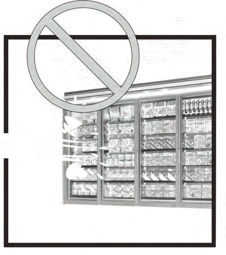
TECHNICAL DOCUMENTATION               STATE REVISION OF THE CHAPTER    IN CONFORMITY
                                                                              WITH THE
PRODUCT       GRANBERING KW        ORD.    DATE            ORD.   DATE        APPROVED
                                                                              ORIGINAL
N° DOC.          IM000239          A       20.July.2020    D                               PAGE             3/13

N° CHAP.                           B       01.Febr.2021    E                               FIRST ISSUE    22.05.2020

                                   C       23.Febr.2021    F                               ISSUE            MKTG

                                                    HANDLING

                                    27"

                                          PESI - WEIGHT - POIDS

                                                  Normal weight             Weight incl. Packing
            Cabinet weight (lb)
                                          KWN5       KWN6         KWN7    KWN5     KWN6        KWN7
                              2D           789            816       860   820       847            891
                              3S           972        1004         1059   1009      1042           1096
           GRANBERING
                              3D          1184        1224         1290   1230      1270           1336
               KW
                              4D          1579        1631         1720   1640      1693           1781
                              5D          1973        2039         2150   2050      2116           2227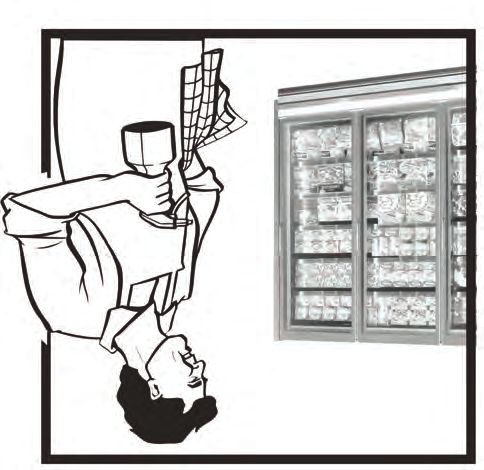
TECHNICAL DOCUMENTATION STATE REVISION OF THE CHAPTER IN CONFORMITY
WITH THE
PRODUCT GRANBERING KW ORD. DATE ORD. DATE APPROVED
ORIGINAL
N° DOC. IM000239 A 20.July.2020 D PAGE 4/13
N° CHAP. B 01.Febr.2021 E FIRST ISSUE 22.05.2020
C 23.Febr.2021 F ISSUE MKTG
INSTALLATION DIAGRAMS
2D
35 3/8 8 1/8
ELECTRICAL REFRIGERATION
6 1/8
ACCESS 2 ½” AIR GAP REQUIRED ACCESS
3/4
3 3/4"
SINGLE COIL
19 5/8 19 7/8"
36 7/8" 35 7/8" DRAIN
PIPING
LEVELLING
FEET
FRONT OF CASE KICKPLATE
7 7/8" 7 7/8" LOCATION
ADD 2’’ TO LENGTH FOR EACH END
NO CLEARANCE REQUIRED AT ENDS OF CASE
24" 24"
3S
35 3/8 8 1/8
ELECTRICAL
6 1/8
3/4 ACCESS 2 ½” AIR GAP REQUIRED REFRIGERATION
ACCESS
3 3/4"
SINGLE COIL
19 5/8 19 7/8"
35 7/8"
DRAIN PIPING
LEVELLING
FEET
FRONT OF CASE KICKPLATE
7 7/8" 7 7/8" LOCATION
ADD 2’’ TO LENGTH FOR EACH END
NO CLEARANCE REQUIRED AT ENDS OF CASE
24" 24"
35 3/8 8 1/8
3D 6 1/8
ELECTRICAL
ACCESS 2 ½” AIR GAP REQUIRED REFRIGERATION
3/4
ACCESS
3 3/4"
SINGLE COIL
19 5/8 19 7/8"
35 7/8"
DRAIN PIPING
LEVELLING
FEET
FRONT OF CASE KICKPLATE
7 7/8" 7 7/8" LOCATION
ADD 2’’ TO LENGTH FOR EACH END
24" NO CLEARANCE REQUIRED AT ENDS OF CASE
24"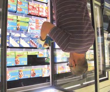
6 1/8
ELECTRICAL
ACCESS 2 ½” AIR GAP REQUIRED REFRIGERATION
3/4
ACCESS
TECHNICAL DOCUMENTATION STATE REVISION OF THE CHAPTER IN CONFORMITY
WITH THE3 3/4"
PRODUCT GRANBERING KW ORD. DATE ORD. DATE APPROVED
SINGLE COIL
ORIGINAL
N° DOC. IM000239
19 5/8 A D 19 7/8"
PAGE 5/13
20.July.2020
N° CHAP. 35 7/8" B 01.Febr.2021 E FIRST ISSUE 22.05.2020
C F PIPING
23.Febr.2021 DRAIN ISSUE MKTG
7 7/8" INSTALLATIONFRONT OF CASE DIAGRAMS
ADD 2’’TO LENGTH FOR EACH END
7 7/8"
KICKPLATE
LOCATION
24" NO CLEARANCE REQUIRED AT ENDS OF CASE
24"
4D 35 3/8 8 1/8
ELECTRICAL
ACCESS 6 1/8
3/4 2 ½” AIR GAP REQUIRED REFRIGERATION
ACCESS
3 3/4"
SINGLE COIL
19 5/8 19 7/8"
35 7/8"
DRAIN PIPING
LEVELLING
FEET
FRONT OF CASE KICKPLATE
LOCATION
7 7/8" ADD 2’’ TO LENGTH FOR EACH END 7 7/8"
NO CLEARANCE REQUIRED AT ENDS OF CASE
24" 24"
5D 35 3/8 8 1/8
ELECTRICAL 6 1/8
ACCESS
REFRIGERATION
3/4 2 ½” AIR GAP REQUIRED ACCESS
3 3/4"
SINGLE COIL
19 5/8 19 7/8"
35 7/8"
DRAIN PIPING
LEVELLING
FEET
FRONT OF CASE KICKPLATE
ADD 2’’ TO LENGTH FOR EACH END LOCATION
7 7/8" 7 7/8"
NO CLEARANCE REQUIRED AT ENDS OF CASE
24" 24"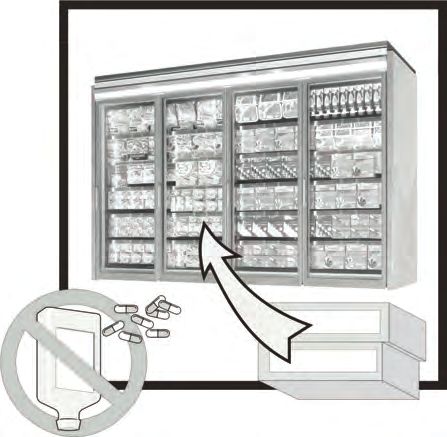
TECHNICAL DOCUMENTATION          STATE REVISION OF THE CHAPTER   IN CONFORMITY
                                                                        WITH THE
PRODUCT       GRANBERING KW   ORD.    DATE           ORD.   DATE        APPROVED
                                                                        ORIGINAL
N° DOC.          IM000239     A       20.July.2020   D                               PAGE            6/13

N° CHAP.                      B       01.Febr.2021   E                               FIRST ISSUE   22.05.2020

                              C       23.Febr.2021   F                               ISSUE           MKTG

                                      LOADING PRODUCTS

                                                                                       OK!

              90° max

LOADING PRODUCTS

IMPORTANT: The door was designed to stay open WITHOUT ANY MECHANICAL
BLOCKING SYSTEM, simply by opening it to a 90° angle. Moreover, the “soft closing”
system ensures slow and gentle AUTOMATIC closing in the final part without the need to
force the door shut.

As a result, IT IS NOT NECESSARY TO PUSH the door open beyond a 90° angle and
block it using weights or HOLD it in position when it is already open at a 90° angle.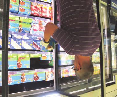
TECHNICAL DOCUMENTATION STATE REVISION OF THE CHAPTER IN CONFORMITY
WITH THE
PRODUCT GRANBERING KW ORD. DATE ORD. DATE APPROVED
ORIGINAL
N° DOC. IM000239 A 20.July.2020 D PAGE 7/13
N° CHAP. B 01.Febr.2021 E FIRST ISSUE 22.05.2020
C 23.Febr.2021 F ISSUE MKTG
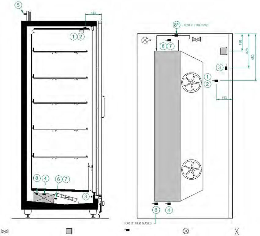
TECHNICAL DATA
POSITIONS SONDES
PROBES LOCATIONS NC5
PROBES POSITION
POSIZIONE SONDE
Détendeur Afficheur Sonde / Bulbe Capteur de pression Orifice tube
Expansion valve Readout box Probe / Bulb Pressure probe Orifice tube
Valvola di espansione Display Sonda / Bulbo Sonda di pressione Orifizio tubo
Emplacement Soufflage Soufflage Reprise d'air Evaporateur Ligne d'aspiration (EEV) Sortie évap. (EEV) Sortie évap. (TEV) Entreè évap. (EEV)
1 2 3 4 5 6 7 8 8*
Location Air outlet Air outlet Air inlet Evaporator Suction line (EEV) Evap.outlet (EEV) Evap.outlet (TEV) Evap.inlet (EEV)
Posizione AO Mandata aria TDA Mandata aria AR Ripresa aria ED Evaporatore Tubo aspirazione (EEV) EO Uscita evap. (EEV) Uscita evap. (TEV) EI Ingresso evap.(EEV)
Type Sonde de température Sonde de température Sonde de température Sonde de température Capteur de pression Sonde de température Bulbe Sonde de température
Type Temperature probe Temperature probe Temperature probe Temperature probe Pressure probe Temperature probe Bulb Temperature probe
Tipo Sonda di temperatura Sonda di temperatura Sonda di temperatura Sonda di temperatura Sonda di pressione Sonda di temperatura Bulbo Sonda di temperatura
Montage Air Air Air Poche Poche Contact tube Poche
Mounting Air Air Air Pocket Pocket Pipe contact Pocket
Montaggio Aria Aria Aria Pozzetto Pozzetto Contatto tubo Pozzetto
Température d'affichage
Fonction de la Régulation / Température affichée sur Régulation de la Régulation de la
du contrôleur / Dégivrage Régulation de la surchauffe Régulation de la surchauffe
sonde Alarme le thermomètre surchauffe surchauffe
Traçabilité
Controller display
Function of Control / Temperature displayed on
temperature / Defrost Superheat control Superheat control Superheat control Superheat control
sensor Alarm the thermometre
Traceability
Visulizzazione a display
Funzione della Regolazione 7 Temperatura visualizzata Regolazione del Regolazione del Regolazione del Regolazione del
del controllore / Sbrinamento
sonda Allarme sul termometro surriscaldamento surriscaldamento surriscaldamento surriscaldamento
Tracciabilità
09/2018 DTP00013.B
EPTA Documents - Confidential - Internal use only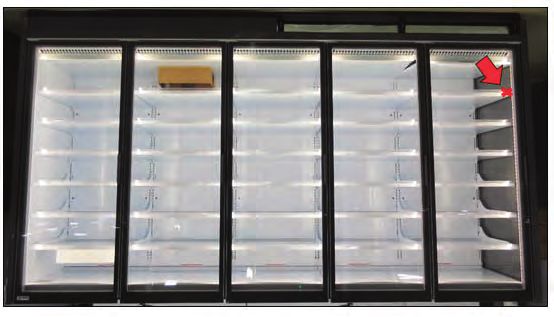
TECHNICAL DOCUMENTATION           STATE REVISION OF THE CHAPTER           IN CONFORMITY
                                                                                 WITH THE
PRODUCT       GRANBERING KW    ORD.    DATE            ORD.    DATE              APPROVED
                                                                                 ORIGINAL
N° DOC.          IM000239      A       20.July.2020    D                                      PAGE            8/13

N° CHAP.                       B       01.Febr.2021    E                                      FIRST ISSUE   22.05.2020

                               C       23.Febr.2021    F                                      ISSUE           MKTG

                                          TECHNICAL DATA

                                                       Piping

                                                                                 2D
                                                                                 2P      3D/3D-S
                                                                                         3P/3P-S      4D
                                                                                                      4P        5D
                                                                                                                5P

                                                      LIQUID      Øext [mm]       10          10       10       10
                              R744
                                                  SUCTION         Øext [mm]       10          10       10       10
GRANBERING
 GranberingKW

                                                      LIQUID      Øext [mm]       10          10       10       10
                      Other Refrigerants
                                                  SUCTION         Øext [mm]       18          18       22       22

                                           Operation mode

   GRANBERING KW
Discharge Air Temperature (°F) Capacities -2 to -2.5/ -2 to -2.5/ -2 to -2.5/
3 Doors -2 to -2.5/
Frozen Food/Ice Cream -12 to -13 -12 to -13 -12 to -13 -12 to -13
TECHNICAL DOCUMENTATION STATE REVISION OF THE CHAPTER IN CONFORMITY
Total Display Area (ft2) WITH THE 30.64
Discharge AirGRANBERING
PRODUCT Velocity (fpm)
KW ORD. DATE ORD. 300
DATE - 400 300 - 400
APPROVED 300 - 400 300 - 400
ORIGINAL
N° DOC. IM000239 A 20.July.2020 D PAGE 9/13
Cubic Capacity (ft3) 66.02
Fan Speed (rpm)
N° CHAP. B 01.Febr.2021 E
2100 2100 2100
FIRST ISSUE
2100
22.05.2020
Max Shelf
Parallel Depth Load
Thermal (Top/Bottom) C
(Btuh) (in) 23.Febr.2021 F 22/22
ISSUE MKTG
1784/1900 2676/2850 3568/3800 4460/4749
Frozen Food/Ice Cream
Weight (.lbs) Thermal Load (Btuh)
Conventional 972
1821/1939 2731/2909 3642/3878 4552/4848
Frozen Food/Ice Cream
Refrigeration Data (All data is per side) 6 - 8
Superheat Setpoint (°F) Cabinet electrical duty 6 - 8 6-8 6-8
Evaporator Temperature (°F)
KWN5
Estimated Refrigerant ‐10/-19
Frozen Food/Ice Cream Charge (.lbs) 1.335 2.214 3.094 3.974
Discharge Air Temperature (°F)
-2 to -2.5/-12 to -13
Frozen Food/Ice Cream
Electrical Data (Amps/Qty)
Discharge Air Velocity (fpm) 300 - 400
115V/60Hz, 1 Phase
0.94 1.41 1.88 2.35
Fans
Fan Speed (rpm) 2100
LED
0.26 0.39 0.52 0.65
GE ELV2
Parallel Thermal Load (Btuh)
2230/2375
FrozenAnti-Sweat
Food/Ice Heater
CreamAmps (F.F.) 1.53 2.28 3.02 3.76
Conventional
208V/60Hz,Thermal
1 Phase Load (Btuh) 7.63 12.69 17.75 2276/2424
22.82
FrozenDefrost
Food Heater
/Ice Cream
Superheat Setpoint (°F) 6-8
Estimated Refrigerant Charge (.lbs) 1.741
Fail Safe Termination Drip Time
Defrost Data Per Day
(min)1 (°F) (min)
Electric 1 25
Electrical Data (Amps/Qty) End Case59 10
115V/60Hz, 1 Phase
1
At ASHRAE conditions. For conditions above 75F, 55% RH, increase defrost time by 15 min. 1.41
Fansintended for use in an area where the environmental conditions are controlled and maintained that conditions do not exceed 75°F and 55% relative humidity.
Type I refrigerator,
Epta Refrigeration, whose policy is one of continuous improvement, reserves the right to change at any time specifications, designs, or prices without incurring obligation.
LED
2017 DOE Compliant
0.39
GE ELV2
Anti-Sweat Heater Amps (F.F.) 2.14
208V/60Hz, 1 Phase
9.97
Defrost Heater
Fail Safe Termination Drip Time
Defrost Data Per Day
(min)1 (°F) (min)
Electric 1 25 59 10
1
At ASHRAE conditions. For conditions above 75F, 55% RH, increase defrost time by 15 min.
Type I refrigerator, intended for use in an area where the environmental conditions are controlled and maintained that conditions do not exceed 75°F and 55% relative humidity.
Epta Refrigeration, whose policy is one of continuous improvement, reserves the right to change at any time specifications, designs, or prices without incurring obligation.
2017 DOE CompliantDischarge Air Temperature (°F) -2 to -2.5/ -2 to -2.5/ -2 to -2.5/ -2 to -2.5/
Frozen Food/Ice Cream Capacities -12 to -13 -12 to -13 -123toDoors
-13 -12 to -13
TECHNICAL DOCUMENTATION STATE REVISION OF THE CHAPTER IN CONFORMITY
Total Display Area (ft2)(fpm) WITH THE
Discharge
PRODUCT AirGRANBERING
Velocity KW ORD. DATE ORD. 300
DATE - 400 300 - 400
APPROVED 300 31.63
- 400 300 - 400
ORIGINAL
N° DOC. IM000239 A 20.July.2020 D PAGE 10/13
Cubic
Fan Capacity
Speed (rpm)(ft3) 2100 2100 68.12
2100 2100
N° CHAP. B 01.Febr.2021 E FIRST ISSUE 22.05.2020
Parallel
Max ShelfThermal
DepthLoad (Btuh) (in)
(Top/Bottom) C 23.Febr.2021 F 22/22
ISSUE MKTG
1820/1939 2731/2908 3641/3877 4551/4846
Frozen Food/Ice Cream
Weight (.lbs) Thermal Load (Btuh)
Conventional 1004
1858/1979 2787/2968 3716/3957 4645/4974
Frozen Food/Ice Cream
Refrigeration
Superheat Setpoint (°F) Data (All data is per
Cabinet side) 6 - 8
electrical duty 6 - 8 6-8 6-8
KWN6
Evaporator Temperature (°F)
‐10/-19
Estimated Refrigerant
Frozen Food/Ice CreamCharge (.lbs) 1.335 2.214 3.094 3.974
Discharge Air Temperature (°F)
-2 to -2.5/-12 to -13
Frozen Food/Ice Cream
Electrical Data (Amps/Qty)
Discharge Air Velocity (fpm) 300 - 400
115V/60Hz, 1 Phase
0.94 1.41 1.88 2.35
Fans
Fan Speed (rpm) 2100
LED
0.26 0.39 0.52 0.65
GE ELV2
Parallel Thermal Load (Btuh)
2276/2423
Frozen Food/Ice
Anti-Sweat Cream
Heater Amps (F.F.) 1.56 2.32 3.07 3.83
Conventional
208V/60Hz, 1Thermal
Phase Load (Btuh)
7.63 12.69 17.75 2323/2473
22.82
Frozen Food/Ice
Defrost Heater Cream
Superheat Setpoint (°F) 6-8
Estimated Refrigerant Charge (.lbs) 1.741
Fail Safe Termination Drip Time
Defrost Data Per Day
(min)1 (°F) (min)
Electric 1 25 59 10
1
At ASHRAE conditions. For conditions aboveElectrical Data
75F, 55% RH, (Amps/Qty)
increase defrost time by 15 min. End Case
Type I refrigerator, intended for use in an area where the environmental conditions are controlled and maintained that conditions do not exceed 75°F and 55% relative humidity.
115V/60Hz, 1 Phase
Epta Refrigeration, whose policy is one of continuous improvement, reserves the right to change at any time specifications, designs, or prices without incurring obligation.
2017 DOE Compliant 1.41
Fans
LED
0.39
GE ELV2
Anti-Sweat Heater Amps (F.F.) 2.18
208V/60Hz, 1 Phase
Defrost Heater 9.97
Fail Safe Termination Drip Time
Defrost Data Per Day
(min)1 (°F) (min)
Electric 1 25 59 10
1
At ASHRAE conditions. For conditions above 75F, 55% RH, increase defrost time by 15 min.
Type I refrigerator, intended for use in an area where the environmental conditions are controlled and maintained that conditions do not exceed 75°F and 55% relative humidity.
Epta Refrigeration, whose policy is one of continuous improvement, reserves the right to change at any time specifications, designs, or prices without incurring obligation.
2017 DOE CompliantDischarge Air Temperature (°F) -2 to -2.5/ -2 to -2.5/ -2 to -2.5/ -2 to -2.5/
Frozen Food/Ice Cream Capacities -12 to -13 -12 to -13 -123toDoors
-13 -12 to -13
TECHNICAL DOCUMENTATION STATE REVISION OF THE CHAPTER IN CONFORMITY
WITH THE
Discharge
Total
PRODUCT
AirArea
Display Velocity
(ft2) (fpm)
GRANBERING KW ORD. DATE ORD.
300 - 400
DATE
300 - 400
APPROVED 300 34.55
- 400 300 - 400
ORIGINAL
N° DOC. IM000239 A 20.July.2020 D PAGE 11/13
Fan Speed
Cubic (rpm)
Capacity (ft3) 2100 2100 2100
74.30 2100
N° CHAP. B 01.Febr.2021 E FIRST ISSUE 22.05.2020
Parallel Thermal Load (Btuh) C 23.Febr.2021 F ISSUE MKTG
Max Shelf Depth (Top/Bottom) (in) 1958/2085 2937/3127 22/22
3916/4169 4894/5212
Frozen Food/Ice Cream
Conventional
Weight (.lbs) Thermal Load (Btuh) 1059
1998/2128 2997/3191 3996/4255 4995/5319
Frozen Food/Ice Cream
Superheat Setpoint (°F)
Refrigeration Cabinet
Data (All electrical
data is per side) 6 - 8 duty 6 - 8 6-8 6-8
Evaporator Temperature (°F)
Estimated Refrigerant Charge (.lbs) 1.335 2.214 3.094 3.974
KWN7
Frozen Food/Ice Cream
‐10/-19
Discharge Air Temperature (°F)
-2 to -2.5/-12 to -13
Frozen Food/Ice Cream
Discharge Air Velocity (fpm) 300 - 400
Electrical Data (Amps/Qty)
Fan Speed (rpm) 2100
115V/60Hz, 1 Phase
0.94 1.41 1.88 2.35
ParallelFans
Thermal Load (Btuh)
2448/2606
FrozenLED
Food/Ice Cream
0.35 0.52 0.70 0.87
GE ELV2
Conventional Thermal Load (Btuh)
2498/2660
FrozenAnti-Sweat
Food/Ice Cream
Heater Amps (F.F.) 1.65 2.46 3.26 4.06
Superheat
208V/60Hz, 1 Phase
Setpoint (°F) 7.63 12.69 17.75 6 -22.82
8
Defrost Heater
Estimated Refrigerant Charge (.lbs) 1.741
Fail Safe Termination Drip Time
Defrost Data Per Day
(min)1 (°F) (min)
Electric 1 25 59 10
1
At ASHRAE conditions. For conditions above 75F, 55% RH, increase defrost time by 15 min.
Type I refrigerator, intended for use in an area where the environmental conditions are controlled and maintained that conditions do not exceed 75°F and 55% relative humidity.
Epta Refrigeration, whose policy is one of continuous improvement, reserves the right to change at any time specifications, designs, or prices without incurring obligation.
2017 DOE Compliant Electrical Data (Amps/Qty) End Case
115V/60Hz, 1 Phase
1.41
Fans
LED
0.52
GE ELV2
Anti-Sweat Heater Amps (F.F.) 2.32
208V/60Hz, 1 Phase
9.97
Defrost Heater
Fail Safe Termination Drip Time
Defrost Data Per Day
(min)1 (°F) (min)
Electric 1 25 59 10
1
At ASHRAE conditions. For conditions above 75F, 55% RH, increase defrost time by 15 min.
Type I refrigerator, intended for use in an area where the environmental conditions are controlled and maintained that conditions do not exceed 75°F and 55% relative humidity.
Epta Refrigeration, whose policy is one of continuous improvement, reserves the right to change at any time specifications, designs, or prices without incurring obligation.
2017 DOE CompliantTECHNICAL DOCUMENTATION STATE REVISION OF THE CHAPTER IN CONFORMITY
WITH THE
PRODUCT GRANBERING KW ORD. DATE ORD. DATE APPROVED
ORIGINAL
N° DOC. IM000239 A 20.July.2020 D PAGE 12/13
N° CHAP. B 01.Febr.2021 E FIR ST ISS UE 22.05.2020
C 23.Febr.2021 F ISSUE MKTG
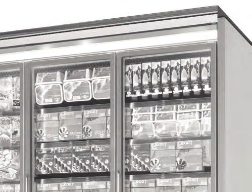
IMPORTANT
The FDA Food Code and NSF/ANSI Standard 7 require that each refrigerated storage
compartment or cabinet shall have at least one securely mounted temperature indica-
ting device that clearly displays the air temperature in the compartment.
The thermometer should be mounted inside the cabinet to reflect the warmest loca-
tion of the food products stored in the cabinet.
An NSF thermometer is shipped with each cabinet to comply with the FDA Food Code
and NSF/ANSI Standard 7. The Kysor Warren part number is 08D10047.
See the “X” in the photo below showing the recommended location where the thermo-
meter should be mounted on the price tag molding for GranBering reach in cabinets
as a guide. It is the responsibility of the end user to determine the warmest location inside
the cabinet where the thermometer should be mounted.TECHNICAL DOCUMENTATION STATE REVISION OF THE CHAPTER IN CONFORMITY
WITH THE
PRODUCT GRANBERING KW ORD. DATE ORD. DATE APPROVED
ORIGINAL
N° DOC. IM000239 A 20.July.2020 D PAGE 13/13
N° CHAP. B 01.Febr.2021 E FIRST ISSUE 22.05.2020
C 23.Febr.2021 F ISSUE MKTG
The thermometer can be attached to the front of the price tag molding as shown
below with the cardboard inserted into the PTM or with double sided foam tape.
Questions regarding the FDA Food Code or NSF/ANSI Standard 7 should be addressed
to local health agencies or officials.
FDA Food Code hyperlink
https://www.fda.gov/
NSF/ANSI Standard 7 hyperlink
https://www.nsf.org/
DO NOT DESTROY
KEEP WITH CABINET OR GIVE TO
STORE MANAGERSECTION 2: USER INSTRUCTIONS REV. “B” 20.July.2021
Modello/Modèle/Model
                         Modell/Modelo/Modelo       Granbering KW

           Fabbricante/ConstructeurManufacturer     EPTA- Via degli Alpini 14 - 32020 Limana (BL) - ITA-
                 Hersteller/Fabricante/Fabricante   LIA Tel. 0437/9681 Telefax 0437/967434

                               ITALIANO                             8
                               FRANÇAIS                             13
                                ENGLISH                             18
                                DEUTSCH                             23
                                ESPAÑOL                             28
                             PORTUGUÊS                              33
INTRODUZIONE - INTRODUCTION - INTRODUCTION - EINLEITUNG - INTRODUCCIÓN - INTRODUÇÃO

                                        Il presente manuale è stato realizzato in modo semplice e razionale affinché
                                        leggendolo conosciate a fondo il vostro mobile . Si raccomanda di leggere
                                        attentamente il contenuto e di conservarlo unitamente al mobile. Il costrut-
                                        tore declina ogni responsabilità per danni causati a persone o cose dovuti
                                        alla mancata osservanza delle avvertenze contenute in questo manuale.
                                        Qualsiasi persona utilizzi questo mobile dovrà leggere il presente manuale
                                        d’uso.

                                          Le présent livret d’instructions a été réalisé de façon simple et
                                          rationelle, pour que Vous puissiez connaître à fond vos meubles. Il
                                          est recommandé de lire attentivement son contenu et de le conser-
   ver avec le meuble. Le constructeur décline toute responsabilité pour les éventuels dommages dus
   au manque d’observation des avertissements et indications contenus dans ce manuel. Quiconque uti-
   lise ce meuble doit en tous les cas lire ce manuel avant de le mettre en marche.

   The present booklet has been formulated in a simple and rational way, in order for the reader to get deeply
   acquainted with his showcase . It must be read carefully and keep near the machine. The manufacturer assumes
   no responsibility for any personal injury or property damage which may be caused by non-compliance with the
   instructions contained in this booklet. Whoever operates the machine must have read this manual beforehand.

   Die vorliegende Gebrauchsanweisung ist einfach zu lesen und gut verständlich, so daß Sie Ihr Kühlmöbel von
   Grund auf kennenlernen können. Lesen Sie die Gebrauchsanweisung sorgfältig durch und bewahren Sie diese
   beim Kühlmöbel auf. Der Hersteller lehnt jede Verantwortung ab für Schäden an Dingen und Personen, die auf die
   Nichtbeachtung der in dieser Gebrauchs- und Bedienungsanweisung enthaltenen Anleitungen zurückzuführen
   sind. Jede Person, die das Kühlmöbel betreiben will, muß vorher diese Gebrauchs- und Bedienungsanweisung
   lesen.

   El presente manual ha sido realizado de manera simple y racional para que leyéndolo Ud. pueda conocer a fondo
   su mueble. Se recomienda leerlo atentamente y conservarlo junto a la máquina. El constructor no se responsabi-
   liza por los daños a personas u objetos, que puedan ser ocasionados por cualquier incumplimiento de las pre-
   scripciones contenidas en el presente manual. Quienquiera que emplee este aparato deberá leer el presente
   manual de uso.

   O presente manual foi realizado de modo simples e racional, a fim de que, ao ser lido, permita conhecer total-
   mente o vosso móvel. Recomenda-se ler atentamente seu conteúdo e conservá-lo sempre junto ao móvel. O fabri-
   cante nega qualquer responsabilidade relativa a danos causados a pessoas ou coisas que seja devido ao não
   respeito das advertências contidas neste manual. Todas as pessoas que utilizarem este móvel deverão ler o pre-
   sente manual de uso.

                                                         2
descrizione generale/description générale/general description/allgemeine Beschreibung/descripción genéral/descrição geral
GranBering KW INTERRUTTORE ILLUMINAZIONE TELETERMOSTATO
Interrupteur éclairage Afficheur
Lighting Switch Remote thermostat
Lichtschalter Fernthermostat
Interruptor iluminación Termostato remoto
fig. 1 Interruptor de luz Teletermóstato
TARGA DATI TERMOMETRO (OPTIONAL)
Plaquette signaletique Thermomètre /en option)
Rating plate Thermometer (optional)
Typenschild mit technischen Daten Thermometer (auf Wunsch)
Placa de características Termómetro (Paragol (optativo)
Placa de dados indicativos Termómetro (opcional)
ILLUMINAZIONE
Eclairage
Lighting
Beleuchtung
Iluminación
Iluminação
BATTICARRELLO (OPTIONAL)
Pare-chocs (en option)
Bumper rail (optional)
Wagenstoßleiste (auf Wunsch)
Paragolpes (optativo)
Pára-choques (opcional)
KWN5 KWN6 KWN7
fig. 2 fig. 3 fig. 4
3trasporto del mobile/transport du meuble/cabinet handling
Transport des Kühlmöbels/transporte del mueble/transporte do móvel
tab. I
Pesi del mobile Peso Normale Peso imballato
Poids du meuble Poids normal Poids avec emballage
Cabinet weight Normal weight Weight incl. Packing
Gewichte des Möbels Nenngewicht Gewicht mit Verpackung
Pesos del mueble Peso normal Peso empaquetado
Pesos do móvel Peso normal Peso com embalagem
(lb)
KWN5 KWN6 KWN7 KWN5 KWN6 KWN7
2D 789 816 860 820 847 891
3S 972 1004 1059 1009 1042 1096
GRANBERING
3D 1184 1224 1378 1230 1270 1336
KW
4D 1579 1631 1775 1640 1693 1781
5D 1973 2039 2324 2050 2116 2227
fig. 4
condizioni ambientali/conditions climatiques/climate conditions/Verhältnisse am Aufstellungsort
condiciones ambientales/condições ambientais
fig. 5 fig. 6
600 lux
75 ºF
55% R.H.
fig. 7
tab. II
75 °F
55% R.H.
600 lux
4caratteristiche tecniche/caractéristiques techniques/technical features/technische Eigenschaften
características técnicas/características técnicas
VISIT WWW.KYSORWARREN.COM FOR TECHNICAL INFORMATION
MODEL
SERIAL NO.
TARGA DATI INDICATIVI
Plaquette signalétique R MIN. DESIGN
PRES. (PSIG) LOW SIDE HIGH SIDE
Rating plate
Typenschild mit technischen Daten WIRE #
Placa de características
Placa de dados indicativos 3,4
EVAP FAN &
V HZ PH
PAN HEATER AMPS
MIN CKT MAX OVERCURRENT
AMPACITY PROTECTION
1,2 ANTI -SWEAT V HZ PH
5,6 LIGHTING V HZ PH
DEFROST V HZ PH
7,8 HEATER
fig. 8
tab. III
ATTENZIONE: l’uso dei divisori interni per vasca e ripiani E’ OBBLIGATORIO al fine di garantire un
corretto funzionamento del mobile
Nelle versioni a 3 e 5 porte i divisori sono forniti di serie.
CAUTION: the use of internal partitions in the base deck and shelves is MANDATORY to ensure cor-
rect cabinet operation.For 3 and 5-door versions partitions are supplied as standard.
ATTENTION: l'utilisation des séparations internes pour cuve et étagères EST OBLIGATOIRE afin de
garantir un fonctionnement correct du meuble. Dans les versions à 3 et 5 portes, les séparations
sontfournies de série.
ACHTUNG: in Bodenwanne und Regalauslage MÜSSEN die Innentrennwände verwendet
werden,damit ein fehlerfreier Möbelbetrieb garantiert ist.Die Ausführungen mit 3 und 5 Türen sind
serienmäßig mit Trennwänden ausgestattet.
ATENCIÓN: el uso de divisorios internos para la cuba y estantes es OBLIGATORIO para garantiza-
run correcto funcionamiento del mueble. En las versiones con 3 y 5 puertas los divisorios están inclui-
dos de forma estándar.
ATENÇÃO: o uso de divisórios interiores na cuba e prateleiras é obrigatório para garantir um cor-
recto funcionamento do móvel.Com as versões de 3 e 5 portas os divisórios são fornecidos de série.
5uso del mobile/utilisation du meuble/use of the cabinet/Gebrauchsanweisung/empleo del mueble/uso do móvel
fig. 9
NON OSTRUIRE
Ne pas obstruer
Do not cover
Nicht verdecken
No tapar
Não obstruir
fig. 10
fig. 11
INTERRUTTORE ILLUMINAZIONE
Interrupteur éclairage
Lighting Switch
Lichtschalter
Interruptor iluminación
Interruptor de luz
fig. 12
fig. 13
fig. 15
6fig. 14
fig. 17
OK!
90° max
fig. 17a
manutenzione ordinaria/entretien ordinaire/ordinary maintenance
Wartung des Möbels/mantenimiento ordinario/manutenção ordinária
1
fig. 19
2
fig. 18
7ITALIANO
1. DESCRIZIONE DEL MOBILE
Il mobile GranBering KW è progettato previsto in due diverse profondità, 4 lunghezze e in due differenti altezze. Il mobile
è progettato per la conservazione di prodotti gelati e surgelati (classe L). Le caratteristiche generali e le dimensioni sono
chiaramente illustrate dai disegni 1, 2, 3, a pag. 3. I pesi del mobile, con e senza imballo, sono riportati nella tabella I a
pag. 4. E’ disponibile una vasta gamma di accessori optional per rendere il mobile ancora più funzionale. Rivolgersi al
servizio di assistenza unico autorizzato.
2. TRASPORTO DEL MOBILE
Il mobile è contenuto in uno specifico imballo provvisto di pedana per la movimentazione con carrelli a forca. Qualora si
debba trasportare l’apparecchiatura utilizzare esclusivamente l’apposita pedana o una equivalente; utilizzare un carrello
elevatore a mano oppure elettrico idoneo al trasporto di questi mobili e con capacità di sollevamento sufficiente (vedi pag.
4 - fig. 4 e tab. I). Le operazioni di movimentazione devono essere svolte dal servizio di assistenza tecnica autorizzato.
3. RICEZIONE ED IMMAGAZZINAMENTO
Prima di prendere in consegna il mobile dal trasportatore, controllare le condizioni dell’imballo. Se il medesimo presenta
danni evidenti all’esterno, può darsi che anche il mobile abbia subito delle conseguenze. In tal caso sballate la macchina
in presenza del trasportatore stesso e firmate, con riserva, il relativo documento di consegna. Eventuali danni dovuti al tra-
sporto o ad errato stoccaggio non sono da attribuire alla casa costruttrice del mobile. Le operazioni di sballaggio sono
riservate al servizio di assistenza tecnica autorizzato. La temperatura di immagazzinamento deve essere compresa fra -13
°F e +131 °F, l’umidità dell’aria deve essere compresa fra 30% e 95%. Il banco deve essere posto al riparo da sole e intem-
perie.
4. INSTALLAZIONE E CONDIZIONI AMBIENTALI
L’apparecchio non può essere collocato in ambienti nei quali vi è presenza di sostanze gassose esplosive.
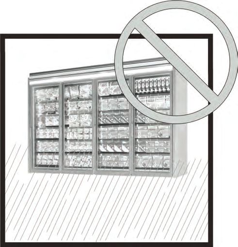
L’apparecchio non può essere usato all’aria aperta e non deve essere esposto alla pioggia.
Prima di collegare il mobile accertarsi che i dati di targa corrispondano alle caratteristiche della rete elettrica a cui deve
essere collegato (vedi pag. 5 - fig. 8 e tab. III). Per un corretto funzionamento del mobile verificare che venga collocato su
un pavimento livellato (vedi pag. 4 - fig. 5), che non sia in prossimità di fonti di calore e/o di radiazione solare diretta non-
ché di porte, finestre, ventilatori e bocche di aerazione con velocità superiore a 0,2 m/s (vedi pag.4 - fig. 6) e che vi sia lo
spazio frontale necessario per permettere l’uso da parte della clientela. Non lasciare esposto l’apparecchio agli agen-ti
atmosferici (fig. 15). L’ambiente nel quale verrà posto il mobile dovrà essere conforme a quanto indicato a pag. 4 - fig.
7 e tab. II.
IMPORTANTE: Il mobile non è dotato di gruppo frigorifero. Per il suo funzionamento è necessario collegarlo ad una unità
motocondensante o centrae frigorifera esterna. IMPORTANTE: non prevedere pannellature fisse sulla parte superiore dei
mobili in quanto questa parte deve RIMANERE ACCESSIBILE per eventuali interventi di manutenzione.
Se richiesto dalle leggi sanitarie locali, lo zoccolo può essere sigillato al pavimento usando un sigillante
siliconico. In occasione degli interventi di manutenzione, rimuovere e sostituire il sigillante.
5. COLLEGAMENTO ELETTRICO
L’installazione deve essere effettuata secondo le istruzioni del costruttore, da personale professionalmente qualificato e
conformemente alle norme sugli impianti elettrici vigenti nei singoli Paesi. Un’errata installazione può causare danni a per-
sone, animali o cose, nei confronti dei quali il costruttore non può essere considerato responsabile.
8Accertarsi che la tensione di alimentazione corrisponda ai dati di targa del mobile, inoltre considerare che le variazioni
massime della tensione di alimentazione consentite sono del +/-6%.
IMPORTANTE: E’ OBBLIGATORIO COLLEGARE IL MOBILE A TERRA. Il costruttore declina ogni responsabilità qua-
lora questa norma anti infortunistica non venga rispettata. Nel caso in cui il mobile debba essere installato lonta-
no dalla fonte di energia elettrica, prevedere un allacciamento in conformità alle Norme vigenti.
IL COSTRUTTORE DECLINA OGNI RESPONSABILITA’ PER EVENTUALI DANNI A PERSONE O COSE PROVO-
CATI DA UNA ERRATA INSTALLAZIONE.
6. CARATTERISTICHE TECNICHE
L’impianto elettrico a bordo macchina è composto da apparecchiature di protezione e controllo opportunamente inserite
nella parte superiore del mobile. I dati tecnici del mobile, riportati anche sulla targhetta dati posta all’interno del mobile
(vedi fig. 8 a pag. 5) sono indicati nella tabella III a pag. 5.
Il livello sonoro generato dal funzionamento del mobile è inferiore a 70 dB(A). Il mobile non provoca vibra-
zioni dannose.
Gli interventi sul termostato sono riservati esclusivamente al personale tecnico di assistenza.
7. CARICAMENTO DEL PRODOTTO
Una volta che il servizio tecnico ha completato l’installazione del mobile, dare tensione all’apparecchiatura agendo sul-
l’interruttore sezionatore generale a parete. A questo punto il mobile inizia il ciclo di raffreddamento. Dopo circa 2 ore dalla
messa in funzione è possibile caricare il mobile con le derrate da esporre già raffreddate alla loro temperatura di conser-
vazione. IL MOBILE E’ REGOLATO IN FABBRICA PER FORNIRE LE PRESTAZIONI PREVISTE.
Nel caricamento delle derrate alimentari prestare la massima attenzione a:
• che il carico sia omogeneo sia per dimensione che per qualità delle derrate;
• che non superi mai il limite di carico di 32,77 lb/ft² per i ripiani e di 46,08 lb/ft² per la vasca,
• che non ostruisca le feritoie che garantiscono il corretto flusso dell’aria refrigerata (vedi fig. 9 a pag. 6).
IMPORTANTE:
La porta è stata progettata per rimanere aperta SENZA ALCUN SISTEMA DI BLOCCAGGIO MECCANICO, semplicemen-
te accompagnandola fino ad un’apertura di 90°. Inoltre, il sistema “soft closing” ne permette una chiusura AUTOMATICA
rallentata e delicata, nel tratto finale, senza sforzarla (fig. 17)
Per tali motivi, NON E’ NECESSARIO SPINGERE l’apertura oltre i 90° e bloccare la porta in questa posizione con qualsi-
voglia peso o APPOGGIARSI alla porta già aperta (fig. 17a)
8. USO DEL MOBILE
Il mobile è stato progettato e realizzato esclusivamente per l’esposizione di derrate alimentari gelate e surgelate (classe L).
I l mobile è atto a conservare la temperatura del prodotto e non ad abbatterla; le derrate, quindi, devono
essere introdotte al suo interno SOLO SE GIÀ RAFFREDDATE ALLE LORO RISPETTIVE TEMPERATURE DI CON-
SERVAZIONE. Per cui, prodotti che abbiano subito un riscaldamento, non devono mai essere introdotti nel
banco.
ATTENZIONE: Per la movimentazione di derrate gelate e surgelate utilizzare guanti imbottiti.
ATTENZIONE: Non lasciare mai aperti o socchiuse le porte. (fig. 1), eviterete inutili consumi di energia e for-
mazioni di brina sulle pareti ottenendo nel contempo una migliore conservazione dei prodotti esposti. Le porte sono
dotate di sistema di chiusura automatico rallentato a partire da una certa angolazione.
COMANDI
9I mobili portano montati nella parte superiore a destra un interruttore che comanda l’illuminazione del prodotto (vedi fig.
12 a pag. 6), un teletermostato sul tetto del mobile (vedi figura 1 a pag. 3) per il controllo della temperatura del mobile.
E’ disponibile anche una termometro optional (vedi figura 1 a pag. 3) che visualizza la temperatura all’interno del banco.
ATTENZIONE: le regolazioni sul teletermostato sono riservate esclusivamente al personale di assistenza.
RIPIANI: I ripiani sono dimensionati per ricevere un carico massimo di 32,77 lb/ft².
9. DIVIETI E PRESCRIZIONI
SI FA ESPRESSO DIVIETO Dl ESPORRE PRODOTTI FARMACEUTICI NEL MOBILE (fig.10).
Non togliere le protezioni o pannellature che richiedono l’uso di utensili per essere rimosse. IN PARTICO-
LARE NON RIMUOVERE LA COPERTURA DEL QUADRO ELETTRICO E LE VITI DI FISSAGGIO DELLE SPINE
PER L’ILLUMINAZIONE DEI RIPIANI.
Attenzione: non rimuovere per nessun motivo gli scorrevoli in vetro. Il mobile è progettato per funzionare
esclusivamente con gli scorrevoli montati.
Non lasciare esposto l’apparecchio agli agenti atmosferici (fig. 15). NON SALIRE sul batticarrello del mobi-
le, NON SALIRE sulla parte superiore del mobile e NON CARICARLA in alcun modo (fig. 11).
Non utilizzate mai getti d’acqua diretti o indiretti sul mobile (fig. 13). Non toccare l’apparecchio con mani
e piedi bagnati o umidi, non usare l’apparecchio a piedi nudi (fig. 14).
OGNI ALTRO USO NON ESPLICITAMENTE INDICATO IN QUESTO MANUALE E’ DA CONSIDERARSI PERI-
COLOSO ED IL COSTRUTTORE NON PUO’ ESSERE RITENUTO RESPONSABILE PER EVENTUALI DANNI
DERIVANTI DA USO IMPROPRIO, ERRONEO ED IRRAGIONEVOLE .
L’installazione dell’apparecchio e dell’unità di condensazione del liquido refrigerante deve essere effet-
tuata solamente dal personale di servizio del costruttore oppure da persona esperta. Le informazioni for-
nire con l’apparecchio dotato di unità di condensazione del liquido refrigerante separata devono com-
prendere:
. informazioni per unità di condensazione separate relative al mobile a cui deve essere collegata:
- uno schema elettrico che mostri i morsetti elettrici per le connessioni.
I BAMBINI DEVONO ESSERE SUPERVISIONATI PERCHÈ NON GIOCHINO CON L'APPARECCHIATURA.
SCELTA DEI LIQUIDI TERMOVETTORI:
Solo i liquidi glicole monoetilenico e glicole monopropilenico con concentrazioni superiori al 30% sono
autorizzati.
Gli impianti per cui sono previsti questi liquidi devono rispettare le norme sanitarie in vigore ed essere
provvisti, in particolare, di un sistema per evitare lo scarico eventuale in acque potabili.
L'uso di un inibitore di corrosione è tassativo.
RACCOMANDAZIONI PER LA MESSA IN SERVIZIO:
Si consiglia vivamente di eseguire una pulizia approfondita degli impianti prima di effettuare il riempi-
mento e uno spurgo completo dell’impianto dopo il riempimento. Per evitare il rischio d’incrostazioni e
di precipitato dei sistemi di inibizione, si raccomanda di usare acqua demineralizzata.
Il pH della soluzione deve essere superiore a 7.
MANUTENZIONE:
Si consiglia di controllare almeno una volta all'anno il pH e la concentrazione della soluzione.
10REFRIGERANTE R744
Il refrigerante R744 è un gas compatiobile con l’ambiente. Fare molta attenzione durante il trasporto,
l’installazione dell’apparecchio e la rottamazione a non danneggiare i tubi del circuito frigorifero.
IN CASO DI DANNI: tenere l’apparecchio lontano da fiamme o fonti di accensione. Ventilare bene l’am-
biente per alcuni minuti. Spegnere l’apparecchio, estrarre la spina di alimentazione. Informare il servi-
zio di assistenza clienti autorizzato.
ATTENZIONE: il sistema refrigerante è ad Alta Pressione. Non manomettere il sistema, ma chiamare un
tecnico specializzato e qualificato prima dello smontaggio.
ATTENZIONE: la manutenzione deve essere eseguita esclusivamente da personale qualificato.
10. MANUTENZIONE ORDINARIA
ATTENZIONE! PRIMA Dl QUALSIASI OPERAZIONE Dl MANUTENZIONE E PULIZIA RISERVATE ALL’UTENTE,
TOGLIERE TENSIONE ALLA MACCHINA TRAMITE L’ INTERRUTTORE SEZIONATORE GENERALE A PARETE (fig.
18)
IMPORTANTE: assicurarsi una buona visibilità nella zona di intervento, eventualmente servendosi di un’ulte-
riore fonte di illuminazione.
RIVESTIMENTO ANTIAPPANNAMENTO PORTE
Le porte del mobile hanno un rivestimento antiappannamento che previene il formarsi di appannamento in
qualsiasi condizione di temperatura ed umidità, anche dopo prolungate immersioni in acqua o frequenti
puliture. Estremamente idrofilico, il rivestimento produce goccioline d’acqua che si propagano e non si tra-
sformano, quindi, in appannamento. Pur assorbendo l’umidità, il rivestimento non si scioglie in acqua e, di
conseguenza, non si macchia se bagnato. La pellicola non viene danneggiata da detergenti commerciali per
vetro, smacchiatori, ammoniaca, alcool e benzina e non si scolorisce se esposta al sole o al calore.
LE PORTE VENGONO FORNITE CON IL RIVESTIMENTO ANTIAPPANNAMENTO LAMINATO SUL VETRO
INTERNO E PROTETTA DA UN LAYER. IL LAYER PROTETTIVO È PARZIALMENTE SOLLEVATO SUI LATI PER
AGEVOLARNE LA RIMOZIONE IN FASE DI UTILIZZO. LA RIMOZIONE DEL LAYER PROTETTIVO DEVE AVVE-
NIRE DOPO L’INSTALLAZIONE DELLE PORTE SUL BANCO UNA VOLTA CHE IL BANCO HA RAGGIUNTO LA
TEMPERATURA DI UTILIZZO, questo per consentire l’immediato funzionamento della pellicola antifog. Per
richiamare questo passaggio sulla pellicola protettiva è apposta la seguente etichetta:” DO NOT REMOVE
THE PROTECTIVE FILM UNTIL THE CABINET HAS REACHED THE OPERATING TEMPERATURE”.
Le superfici trattate possono essere pulite utilizzando comuni detergenti per vetro ed una spugna, uno strac-
cio o un asciugamano di carta. Non vanno utilizzati detergenti che contengono abrasivi, acidi potenti o
sostanze caustiche. Gli eventuali residui untuosi provocati dal fumo di sigaretta o da olii trasportati dall’a-
ria possono, se non eliminati, diminuire le proprietà antiappannamento. La contaminazione untuosa va
rimossa con smacchiatori per sostanze oleose
PULIZIA DEL MOBILE
1) Pulire con cadenza settimanale tutte le parti esterne del mobile utilizzando esclusivamente acqua tiepida e sapone o
detergente neutro di uso domestico diluito in acqua. Asciugare il tutto con cura servendosi di uno straccio morbido. Non
utilizzare assolutamente prodotti infiammabili o abrasivi come alcool, acetone o solventi. NON USARE MAI GETTI D’AC-
QUA PER LA PULIZIA DEL MOBILE. Per le superfici in vetro usare unicamente prodotti per la pulizia dei vetri. Non è consi-
gliabile usare acqua in quanto può depositare calcare sulla superficie del vetro.
ATTENZIONE: NON LAVARE O PULIRE CON ACQUA O LIQUIDI LA PARTE SUPERIORE DEL MOBILE.
112) Pulire con cadenza mensile tutte le parti interne del mobile seguendo le medesime indicazioni riportate al punto prece-
dente.
3) Ogni tre mesi procedere allo sbrinamento del banco per permettere lo scioglimento del ghiaccio che si può esse-
re formato sulle alette dell’evaporatore impedendone il corretto funzionamento. Agire come di seguito descritto:
· Togliere la tensione elettrica al banco tramite l’interruttore sezionatore generale a parete (fig. 19).
· Svuotare il banco, stoccando tutti i prodotti in celle o refrigeratori atti a mantenerne la temperatura di conservazione.
· Attendere che l’interno del banco abbia raggiunto la temperatura ambiente.
· Pulire accuratamente l’interno del banco con acqua tiepida e sapone neutro, quindi asciugare con cura con un panno
morbido.
· Dopo aver controllato attentamente che l’interno del banco sia completamente asciutto, rimettere in funzione l’appa-
recchio ridando tensione al banco.
· Dopo circa un paio d’ore caricare nuovamente il prodotto.
ATTENZIONE: Eseguire le operazioni di montaggio e smontaggio in modo lento e con l’ausilio di guan-
ti da lavoro. Si consiglia di far eseguire queste operazioni di pulizia dal servizio tecnico autorizzato.
QUALSIASI OPERAZIONE DI MANUTENZIONE NON PREVISTA AI PUNTI PRECEDENTI, VA EFFETTUATA DAI
CENTRI DI ASSISTENZA AUTORIZZATI DAI NOSTRI RIVENDITORI O DA PERSONALE QUALIFICATO.
ILLUMINAZIONE : la sostituzione delle lampade è riservata al servizio tecnico di assistenza al quale vi invi-
tiamo a rivolgervi qualora sussistesse questa necessità.
11. SITUAZIONI DI EMERGENZA
1) In caso di rottura dei vetri dell'alzata, assicurarsi che venga tolta l'alimentazione elettrica delle porte.
2) Il mobile non parte o si arresta:
• verificare che non vi sia una situazione di black-out elettrico;
• controllare che l’interruttore generale a parete sia acceso;
Nel caso l’interruzione elettrica non dipendesse da questi motivi chiamare immediatamente il più vicino cen-
tro di assistenza e procedere allo svuotamento completo ed allo stoccaggio immediato del prodotto in celle
o refrigeratori atti a mantenerne la temperatura di conservazione.
3) Il mobile non raffredda a sufficienza:
• controllare che il caricamento del mobile sia corretto e che le prese d’aria non siano ostruite;
• sbrinare e pulire il mobile per poi riprendere il funzionamento normale (vedi parag. 10);
• controllare che il mobile non sia in vicinanza di fonti di calore o di correnti d’aria;
• controllare tramite una livella la planarità del mobile. Verificare che le condizioni ambientali siano conformi a quanto
indicato a pagina 4.
Se il mancato raffreddamento persistesse rivolgersi al più vicino centro di assistenza.
4) Il mobile è rumoroso:
• controllare che viti e bulloni siano perfettamente chiusi;
• controllare, tramite una livella, che il mobile sia ben livellato.
IN CASO DI FUGA DI GAS O DI INCENDIO, non sostare con la testa nel vano se questo non è stato prima opportuna-
mente aerato. Scollegare il mobile agendo sull’interruttore generale a monte dell’apparecchiatura (fig. 19). NON USARE
ACQUA PER SPEGNERE LE FIAMME MA SOLO ESTINTORI A SECCO.
1212. ASSISTENZA TECNICA
Qualora si rendesse necessario l’intervento del personale tecnico di assistenza contattare immediatamente Kysor Warren:
telefono: 1-800-866- 5596
email: KWParts@kysorwarren.com
Qualora vi fosse la necessità di usare pezzi di ricambio fare sempre riferimento al servizio tecnico di assistenza: chiede-
re ed accertarsi che vengano utilizzati ricambi originali.
13. SMANTELLAMENTO, ELIMINAZIONE DEL MOBILE.
In conformità alle norme per lo smantellamento dei rifiuti vigenti nei singoli paesi e per il rispetto dell’ambiente in cui
viviamo, vi preghiamo di dividere le parti del mobile in modo da poterle smaltire separatamente od eventualmente recu-
perare opportunamente. Tutte le parti componenti la macchina non sono assimilabili ai rifiuti solidi urbani fatta eccezio-
ne per le parti metalliche che comunque non figurano tra i rifiuti speciali per la maggior parte dei paesi europei. I COM-
PONENTI DEL CIRCUITO Dl REFRIGERAZIONE NON DEVONO ESSERE TAGLIATI E/O SEPARATI MA DEVONO ESSE-
RE PORTATI INTEGRI IN CENTRI SPECIALIZZATI PER IL RECUPERO DEL GAS REFRIGERANTE.
13ENGLISH
1. DESCRIPTION
These display cases are available in four different lengths and in three different heights. The low-temperature version of this
display case is designed for the preservation of ice cream and frozen food. Its main features and dimensions are illustrated
in Figures 1, 2, and 3 on Page 3. For weights, including and not including crating, see Table 1 on Page 4. A wide variety
of optional accessories enabling enhanced functions is also available. For optional accessories, contact authorized after-
sales support only.
2. TRANSPORTATION
The display case is contained in a specially crated package that enables transportation by the use of forklifts. Handle the
display case on its own pallet or on a similar platform. Use a forklift, either manual or electric, provided it is rated for hand-
ling such display cases and it has the required lifting capacity (see Page 4 – Figure 4 and Table 1). Handling should only
be performed by authorized personnel.
3. DELIVERY AND STORAGE
Prior to accepting the display case from the carrier, check the condition of the packaging. If visible damage can be seen,
the display case may also have been damaged. In this situation, unpack the display case in the presence of the carrier and
sign, with reservation, the delivery receipt. The manufacturer assumes no liability for damage caused by transportation or
incorrect handling. Unpacking is reserved for authorized personnel. Storage dry bulb temperature must be between -13 °F
and +131 °F and air percent relative humidity between 30% and 95%. Keep the display case from being exposed to direct
sunlight and the weather.
4. INSTALLATION AND AMBIENT CONDITIONS
The display case must not be installed in premises containing explosive gas substances. It should not be used in the open
nor be exposed to rain.
Before connecting the display case ensure that its rating plate data match the specifications of the existing electrical
installation (see Page 5 – Figure 8 and Table III). For correct operation, the display case must be placed on a level floor
(see Page 4 - Figure 5), away from sources of heat and/or direct sunlight, doors, win-dows, fans or ventilation outlets
(see page 4 - Figure 6). The area in front of the case must be open and accessible for customer service.
The display case must be installed in a room conforming to the ambient requirements stated in Page 4 –Figure 7
and Table 2.
IMPORTANT: Installing a permanent soffit on the top of the display case is not recommended because the top of the
display case must be accessible for servicing purposes.
If required by local health codes, the kick plate may be sealed to the floor using a silicone type sealant. The sealant
must be removed and replaced when servicing.
5. ELECTRICAL CONNECTION
The display case must be installed by professionally qualified personnel, in accordance with the instructions
provided by the manufacturer and local regulations. Incorrect installation may cause harm to persons, ani-
mals or property. The manufacturer assumes no responsibility for such damage.
Ensure that the system power supply voltage corresponds to the values appearing on the data plate of the
display case.
The maximum allowable power supply voltage variation is +/-6%.
14IMPORTANT: THE EQUIPMENT MUST BE PROPERLY GROUNDED. The manufacturer assumes no responsibility for any
damage resulting from not properly grounding the display case. If the display case must be installed far away from electric
power source, ensure that the connection complies with regulations.
THE MANUFACTURER DISCLAIMS ALL RESPONSIBILITY FOR ANY PERSONAL INJURY OR PROPERTY DAMAGE
ARISING FROM INCORRECT INSTALLATION.
6. TECHNICAL SPECIFICATIONS
The built-in electrical installation is composed of control devices located on top of the refrigerated display case. The elec-
trical specifications are printed on the data plate located on the ceiling panel inside the display case (see Figure 8 on Page
5) as shown in Table III, Page 5.
The sound level generated by the display case is below 70 dB(A). The refrigerated display case generates no harmful vibra-
tions.
7. LOADING PRODUCTS
Once technicians have completed the display case installation, turn it on. The display case will then start its cooling cycle.
Allow the display case to operate for about two hours before loading food products. Food products must already be at their
storage temperature.
When loading products ensure that:
• They are similar in size and type;
• The load limit (32.77 lb/ft² for the shelves and 46.08 lb/ft² for the well) is not exceeded;
• Products do not cover the slots in the return air grille that ensure correct circulation of cool air (see Figure 9 on Page 6).
IMPORTANT:
Doors are designed to stay open WITHOUT ANY MECHANICAL BLOCKING SYSTEM, simply by opening them to a 90°
angle. Moreover, the "soft closing" system ensures slow and gentle AUTOMATIC closing to the closed position without the
need to force the door closed (See Figure 17).
IT IS NOT NECESSARY TO PUSH the door open beyond a 90° angle and hold it open using weights or HOLD it in posi-
tion when it is already open at a 90° angle (See Figure 17a).
8. USE
The display case was designed and manufactured exclusively for the display of ice-cream and frozen food. Its function is
to maintain food at its storage temperature, not reduce it or pull it down from a warmer temperature. Therefore, when loa-
ded, THE FOOD PRODUCTS MUST BE AT THEIR STORAGE TEMPERATURE. Do not load foods that have undergone hea-
ting. Use padded gloves when handling ice cream and frozen food products.
OPEN DOOR LOCKING SYSTEM
For loading and cleaning purposes the doors can be locked in open position by shifting the locking system as shown by
the arrow in the Figure 16 on Page 7.
DOOR CLOSING SPRING
Never remove the gas springs that would allow the doors to remain open or ajar (Figure 1). If the gas springs are remo-
ved, higher energy consumption will be experienced and frost build-up will occur on the walls.
CONTROLS
On the top front right of the display case is a switch to control lighting and a thermometer for indicating temperature. The
thermometer displays the supply air temperature inside the case.
SHELVES: Shelves are designed to bear a maximum structural load of 32.77 lb/ft².
159. RESTRICTIONS
Storing pharmaceutical products in the display case is strictly forbidden (See Figure 10).
Do not remove covers or panels when they require the use of tools. IN PARTICULAR, DO NOT REMOVE THE ELECTRICAL
CONTROL PANEL COVER.
Do not expose the display case to atmospheric agents (Figure 15). DO NOT STEP on the display case bumper rail. DO
NOT STEP on the top of the display case and DO NOT PLACE WEIGHT on top of the display case (See Figure 11).
Caution: Never remove the gas springs. The display case was designed to only work with the gas springs attached to the
doors.
Do not spill water directly or indirectly on the display case (See Figure 13). Do not touch the equipment with damp or wet
hands or feet. Do not use it while barefoot (See Figure 14).
ANY OTHER USE NOT EXPRESSLY MENTIONED IN THIS MANUAL MUST BE CONSIDERED HAZARDOUS.
THE MANUFACTURER ASSUMES NO RESPONSIBILITY FOR ANY DAMAGE RESULTING FROM IMPROPER, INCORRECT
OR UNREASONABLE USE.
10. ORDINARY MAINTENANCE
ATTENTION! BEFORE STARTING ANY MAINTENANCE OR CLEANING, DISCONNECT THE EQUIPMENT
FROM THE ELECTRICAL POWER SUPPLIES (SEE FIGURE 19).
IMPORTANT: During maintenance or cleaning operations, ensure that lighting in the working area is suffi-
cient and if necessary, use an additional source of light.
DOOR ANTIFOG LINER FILM
Display case doors are provided with an anti-fog film on the interior of the glass that prevents mist from buil-
ding up in any temperature and humidity condition, even after long immersion in water or frequent cleaning.
Being extremely hydrophilic, this film causes water drops to condense and disperse without turning into mist.
However water absorbing, the anti-fog film does not dissolve in water and consequently does not get stained
when soaking wet. The anti-fog film is not damaged by commercial glass cleaners, stain removers, ammo-
nia, alcohol or benzene and does not undergo discoloring when exposed to sunlight or heat.
DOORS ARE PROVIDED WITH AN ANTI-FOG FILM LAMINATED ONTO THE INTERNAL SIDE OF THE GLASS, AND IS
GUARDED BY A PROTECTIVE PLASTIC FILM. THE EDGES OF THE PROTECTIVE FILM ARE SLIGHTY LIFTED IN ORDER FOR
THE PLASTIC FILM TO BE EASILY REMOVED FOR USE. THE PROTECTIVE PLASTIC FILM MUST BE REMOVED AFTER THE
DOORS HAVE BEEN FITTED ONTO THE CABINET AND ONLY WHEN THE CABINET HAS REACHED OPERATING TEM-
PERATURE, SO THAT THE ANTI-FOG FILM WILL START TO FUNCTION IMMEDIATELY. THERE IS A LABEL APPLIED ON THE
PROTECTIVE PLASTIC FILM:
“DO NOT REMOVE THE PROTECTIVE PLASTIC FILM UNTIL THE CABINET HAS REACHED THE OPERATING TEMPERA-
TURE”.
Anti-fog surfaces may be cleaned using common glass cleaner and a sponge, a rag or a paper towel. Do not use deter-
gent containing abrasive, strongly acidic or caustic substances. Unless removed, greasy residue from cigarettes or airborne
oil may diminish the film's anti-fog properties. Greasy residue must be removed using oil stain remover.
16REFRIGERANT R744
Refrigerant R744 is an environmentally friendly refrigerant. Use great care during transport, installation and dismantling to
prevent damage to the refrigeration piping.
IN CASE OF DAMAGE: Keep the unit away from flames or ignition sources. Ventilate the premises well for a few minutes.
Disconnect power supplies. Inform an Authorized Service Centre.
CAUTION: The refrigeration system is High Pressure. Do not tamper with the system and contact a qualified, specialized
technician before disassembly.
CAUTION: Maintenance should be carried out only by qualified or authorized personnel.
Children should be supervised to ensure they do not play with the unit.
CLEANING THE DISPLAY CASE
1) Every week clean the outer surfaces of the display case with mild soap or detergent in lukewarm water only.
Wipe carefully with a soft cloth. Never clean it using flammable or scouring agents, alcohol, acetone or solvents.
NEVER CLEAN THE DISPLAY CASE USING HIGH PRESSURE WATER JETS.
Clean glass surfaces using glass-cleaning products exclusively. The use of water is not recommended as it may cause scale
to build up.
CAUTION! NEVER WASH OR CLEAN THE TOP OF THE DISPLAY CASE WITH WATER OR LIQUIDS!
2) Every month clean the inside surfaces following the instructions provided in the preceding item.
3) Every three months clean the return air grilles under the bottom shelfs.
4) Defrost the display case every three months to let the ice that may have formed and accumulated between the fins melt.
Frost may otherwise prevent correct operation. Proceed as follows.
· Disconnect the display case from the electrical power supply.
· Empty the display case and store the contents in cold rooms or refrigerators that are adequate for maintaining the cor-
rect storage temperature.
· Wait until the display case has reached ambient temperature.
· Clean the inside of the display case thoroughly with mild soap or detergent and lukewarm water. Wipe carefully with a
soft cloth.
· After carefully checking that the display case is completely dry inside, restart the display case again.
· Allow a couple of hours for the case to pull down to steady state operating temperature before loading the products.
Attention! Disassemble and assemble very slowly, using heavy-duty gloves. It is recommended to have clea-
ning operations carried out by authorized service personnel.
ANY MAINTENANCE OPERATION NOT INCLUDED IN THE PREVIOUS STEPS MUST BE CARRIED OUT BY
AUTHORIZED AFTER-SALES SERVICE OR BY QUALIFIED PERSONNEL.
LIGHTING: Lamps must be replaced by after-sales service personnel only.
11. EMERGENCY SITUATIONS
1) Should the door glass break, ensure that the doors are disconnected from the power supply.
17You can also read