TVS 2300 INTERCOOLED SUPERCHARGER KIT INSTALLATION MANUAL
←
→
Page content transcription
If your browser does not render page correctly, please read the page content below

HOLDEN COMMODORE VE-VF V8
                          6.0L & 6.2L GEN 4 (2006-2013)

                              TVS 2300 INTERCOOLED
                                SUPERCHARGER KIT
                              INSTALLATION MANUAL

                         For any further technical information contact:

                           Centrifugal Air Pumps Australia Pty Ltd
                             20 Verrall Cres, Berri SA 5343, Australia
                                 Email sales@capadrift.com.au
                           Phone 08 8582 3499 (Intl. +61 8 8582 3499)

VEVF2300-MANUAL – V1.0                   Printed April 20, 2020           -0-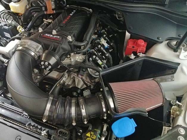
INTRODUCTION
Application:
2006+ Holden and HSV models equipped with a 6.0L & 6.2L Engine
(Manual & Automatic Transmission)
NOT Suitable for HSV LS-2
Important Notes:
Before installing your SLP CAPA Supercharger Kit, please read the installation manual and
verify that all items are present. If you are missing hardware or have any questions, please
contact CAPA Performance on (08) 8582 3499.
Premium fuel (98 octane or higher) is REQUIRED to prevent “spark-knock” or
detonation under certain operating conditions.
Operating your engine without the ECU / PCM recalibration will result in engine damage
or failure and will void your warranty.
The use of fuel additives (ie. octane boosters) is not recommended. There is a possibility
that these chemicals can damage your engine and cause drivability issues with your
vehicle.
If the vehicle being equipped with the supercharger kit is an automatic, please check your
DOD plate as shown on the next page PRIOR to beginning the kit installation. Failure to
do so will result in a delay of your build.
VEVF2300-MANUAL – V1.0 Printed April 20, 2020 -1-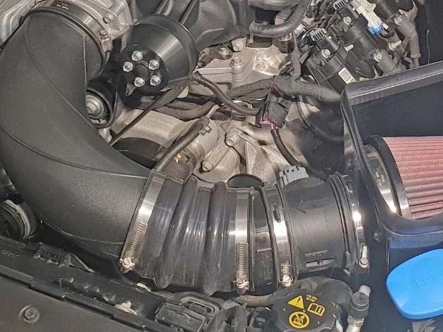
ATTENTION
       IMPORTANT NOTE FOR VEHICLES EQUIPPED WITH AN AUTOMATIC TRANSMISSION (L76 /
       L77 ENGINE). CHECK THIS PRIOR TO INSTALLING SUPERCHARGER KIT TO AVOID DELAYS.

       IF YOUR CAR IS EQUIPPED WITH AN AUTOMATIC TRANSMISSION, PLEASE CONFIRM WHICH
       DISPLACEMENT ON DEMAND (DOD) PLATE YOUR VEHICLE WAS BUILT WITH. THIS CAN
       ONLY BE DONE BY REMOVING THE INTAKE MANIFOLD ASSEMBLY AND LOOKING IN THE
       ENGINE VALLEY. THE PLATE ON THE LEFT – GM P/N 12571609 IS THE PLATE THAT WORKS
       WITH THE SUPERCHARGER KIT. IF YOU HAVE THE PLATE ON THE RIGHT (WITH THE RAISED
       SURFACES HIGHLIGHTED), YOU WILL NEED TO ORDER THE OTHER PLATE. PLEASE CALL
       YOUR LOCAL HOLDEN DEALER TO OBTAIN A NEW PLATE.

       The plate shown on the right has large bosses as circled. If you have this plate on your L76
       / L77 Engine you will need to replace the component to complete the installation.

VEVF2300-MANUAL – V1.0                    Printed April 20, 2020                                -2-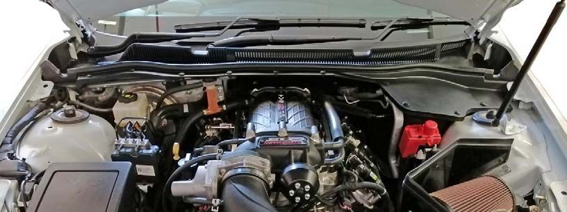
TABLE OF CONTENTS
Glossary of Terms........................................................................................................................................................ 4

Packing List................................................................................................................................................................... 5

Equipment and Supplies Required...................................................................................................................... 7

INFORMATION ABOUT THE SUPERCHARGER BYPASS OPERATION ......................................................... 8

LIMIT OF LIABILITY STATEMENT ........................................................................................................................... 8

SAFETY PRECAUTIONS ............................................................................................................................................. 9

SECTION A – DISASSEMBLY .................................................................................................................................... 10

SECTION B – MODIFICATIONS ............................................................................................................................... 16

             Throttle Body Removal ............................................................................................................................. 16
             EVAP Solenoid Bracket Modification & Relocation.......................................................................... 16

SECTION C – SUBASSEMBLY .................................................................................................................................. 18

             Intercooler Low Temperature Radiator (LTR) .................................................................................... 18
             EVAP Hose Assembly ................................................................................................................................. 19
             Intake Manifold Build Up........................................................................................................................... 20
             Degas Bottle Mounting Bracket ............................................................................................................. 23
             Intercooler Pump Wiring Harness ......................................................................................................... 24

SECTION D – INSTALLATION .................................................................................................................................. 25

             Intake Manifold and Supercharger........................................................................................................ 25
             FEAD Assembly ............................................................................................................................................ 31
             Wiring .............................................................................................................................................................. 33
             Intercooler Pump Mounting.................................................................................................................... 34
             Intercooler Radiator Assembly Mounting .......................................................................................... 39
             Intercooler Degas Bottle Mounting ...................................................................................................... 41
             Intercooler Hose Routing ......................................................................................................................... 43
             Air Induction System.................................................................................................................................. 46
             Final Assembly ............................................................................................................................................. 49

APPENDIX A - L99 CAMARO DOD PLATE INSTALLATION .......................................................................... 50

VEVF2300-MANUAL – V1.0                                                        Printed April 20, 2020                                                                            -3-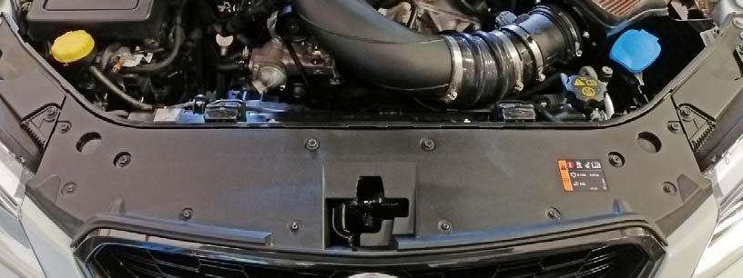
GLOSSARY
Breakout Point           A place in an electrical harness where the wiring for an individual component
                         leaves (breaks out of) the main harness to attach to the component.

ECU                      Electronic Control Unit (Vehicles Computer)

ETC                      Electronic Throttle Control

FEAD                     Front-End Accessory Drive or Front Engine Accessory Drive

LTR                      Low Temperature Radiator (a.k.a Heat Exchanger)

MAFS                     Mass Air Flow Sensor

MAP                      Manifold Absolute Pressure Sensor

PCM                      Powertrain Control Module (a.k.a. ECM, ECU, PCU, EEC)

PCV                      Positive Crankcase Ventilation

TPS                      Throttle Position Sensor

VMV                      Vapour Management Valve (a.ka. Canister Purge Valve)

VEVF2300-MANUAL – V1.0                       Printed April 20, 2020                              -4-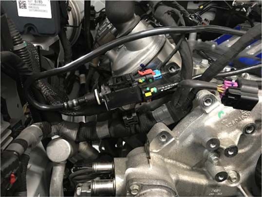
KITS PARTS LIST
                                                                                                Quantity   Checked
       Air Induction                                                          ---
       Tapered Conical Air Filter w/ Clamp- 6” ID, 7.25” OD, 9”     H         VEVF-TVS-FILTER     1
       Air Filter Adapter                                                     VEVF-TVS-FILADA     1
       Air Filter Shroud                                                      VEVF-TVS-AIRDAM     1
       Weather Strip, 28 1/2”                                                 VEVF-TVS-WEATHR     1
       Coupler Sleeve – Air Filter Adapter to Airflow Meter                   VEVF-TVS-MAFJNR     1
       Coupler Sleeve – Airflow Meter to Angled Plastic Joiner                25180042            1
       Angled Plastic Airflow Meter Joiner                                    VEVF-TVS-ANGJNR     1
       Bellows Coupler – Clean Air Tube to Air Box                            100064010           1
       Clamps – Clean Air Tube Coupler                                        210144126           2
       Clean Air Tube                                                         21012521            1
       Coupler Sleeve – Clean Air Tube to Throttle Body                       25180042            1

       Fuel Charging Assembly                                                 HH-9H487            1
       SLP TVS2300 Supercharger Assembly                                      HH-6F066            1
       Fuel Rail                                                              HH-9F792            1
       Fuel Supply Line Jumper                                                CP92266218          1
       Fuel Line Disconnect Tool                                              ---                 1

       Hardware Kit A – Fuel Charging                                         HH-HWKA             1
       Bolts- Throttle body to S/C Inlet: M6 x 1.00 x 40                      R18020004           4
       Fuel Injectors (56 #/HR @ 4 Bar)                                       0280158187          8
       Gasket - S/C to Upper                                                  R07060166           1
       Gasket - Supercharger Bypass                                           R07060183           1
       Gasket Set – Intake to Cylinder Head (Pack of 8)                       19256623            1
       Bolts - S/C to Intake (M8 x 1.25 x 53)                                 N808130             8
       Bolts - Fuel Charging to Cylinder Head (M6 x 1.0 x 74.5)               N807072             10
       Bolts - Fuel Rail (M6x1.0 x32.5)                                       R18020009           4
       Bolt - TMAP to Upper Intake (M6x1x16)                                  W500213             1
       TMAP Sensor                                                            90423637            1
       Badge – SLP (Front of Supercharger)                                    010036203           1
       Badge - TVS2300 (Top of Supercharger)                                  010036202           1
       Bolt – M4x16 (Badge Mounting)                                          940706400           4

       FEAD                                                                   ---
       Idler Mounting Bracket                                                 HH-8B653            1
       Tensioner Assembly                                                     12569301            1
       Supercharger Pulley – 6-Rib                                            HH-6K88CP           1
       Serpentine FEAD Belt (VE Early Models) (6PK2490-6PK2500)               904068124           1
       Serpentine FEAD Belt (VE Late Models) (6PK2480)                        904068124           1
       Serpentine FEAD Belt (VF Models) (6PK2375)                             904068125           1
       Bottom Idler w/ Machined Spacer (VE Early Models)                      CPIDLERVE1          1
       Bolt – M10x120 w/ Spring & Flat Washer (VE Early Models)               CPM10X120SF         1

       Hardware Kit B – FEAD                                                  HH-HWKB             1
       Idler - B/S Non-Flanged                                                08567-32            1
       Bolt- S/C Pulley (M6X1.0X16)                                           W500013             5
       Bolt - Idler to FEAD Bracket (M8 x 1.25 x 28)                          R18020060           1
       Bolt - Idler Bracket to Engine (M8 x 1.25 x 45)                        HHCS8X1.25X95       2
       Bolt - Idler Bracket to Engine (M8 x 1.25 x 95)                        HHCS8X1.25X130      1
       Washer - M8 2MM Thick                                                  M82MM               3

Parts List Continued on Next Page…
VEVF2300-MANUAL – V1.0                                   Printed April 20, 2020                            -5-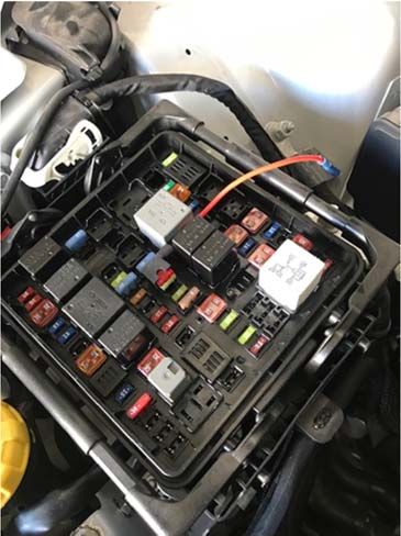
KITS PARTS LIST, CONTINUED
                                                                                        Quantity   Checked
       Hardware Kit C - Wiring                                           HH-HWKC          1
       Electrical Jumper Mini– Intercooler Pump - VE Model               HH-8W501         1
       Electrical Jumper Micro – Intercooler Pump - VF Model             CP54411BL        1
       TMAP / MAF Wiring Harness                                         HH-12A690        1
       Fuse Connector                                                    R18060010        1
       10 Amp Fuse                                                       08N2483          1
       Self Tapping Fastener for Relay                                   R07030003        1

       Hardware Kit D - PCV & Vacuum                                     HH-HWKD          1
       3/8" Hose SAE30R7 w/Clamps - PCV Fresh Air Inlet - 350mm          HH-6758          1
       3/8" Hose SAE30R7 w/Clamps- PCV Purge Tube - 520mm                HH-6K817         1
       5/16" Hose SAE30R7 w/Clamps – Rocker Cover to S/C - 335mm         DMHCP-3312       1
       1/2" Hose SAEJ1403 - Brake Booster - 710mm                        DMHCP-5429       1
       Constant Tension Clamp – Brake Booster Hose 1/2"                  2UTG7            2
       7/32" Vacuum Harness - S/C Bypass - 191mm                         R18140001        1

       Intercooler System                                                ---
       Degas Bottle                                                      R07070007        1
       Degas Bottle Mounting Bracket (2006+ Model Years)                 HH2010-6B364     1
       Radiator Bracket Rubber Mount – (VF Models)                       CP2116165        1
       Radiator Support Bracket – (VE Models)                            CP92265004       1
       Intercooler Electric Water Pump                                   F8YZ-8501        1
       Intercooler Low Temp Radiator (LTR)                               HH-8K229         1

       Hardware Kit E – Intercooler Hoses                                HH-HWKE          1
       Degas to I/C Pump - 3/4" hose x 435mm (17.125")                   HH-8D029         1
       I/C Pump to LTR - 3/4" hose x 622 mm (24.5")                      HH-8K236         1
       LTR to CAC - 3/4" hose x 1524mm (60")                             HH-8D030         1
       CAC to Degas - 3/4" hose x 800mm (31.5")                          HH-8D031         1
       Clamps - 3/4" Constant Tension                                    CT19X12-BO       8

       Hardware Kit F – Intercooler System                               HH-HWKF          1
       I/C Pump Mounting- P-Clip 2.25" I.D. x 3/4" Wide                  F523-036CA       1
       Bolt, Nyloc Nut and Washers – (M8 x 1.25 x 20)                    BNW820           1
       Cap - Degas Bottle                                                9C3Z-8101        1
       Nut - M6x1.0 (Degas Bottle to Mounting Bracket)                   W520412          2
       I/C Pump Mount Bracket                                            CPWPMBR          1

       PLUG - 1/8" NPT                                                   W706310          1
       Foam Tape- 25.4MM x 4.763MM x 65MM                                HH-8K231         2
       Foam Tape: 25.4MM x 12.7MM x 570MM                                HH-8K232         2
       Foam Tape: 25.4MM x 12.7MM x 35MM                                 HH-8K233         1

       Hardware Kit G - Decals / Labels & Instructions                   HH-HWKG          1
       Decal – Premium Fuel Only                                         0102040127       1
       Decal - EO                                                        HH09-9A095EO     1
       Installation Manual                                               HH-6006IM        1

        Important before beginning installation, verify that all parts are included in the kit.
       Report any shortages or damaged parts immediately. Please call us on (08) 8582 3499.

VEVF2300-MANUAL – V1.0                              Printed April 20, 2020                         -6-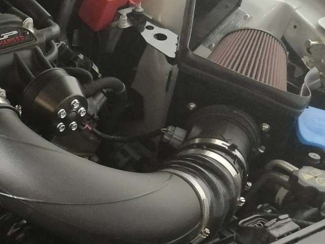
EQUIPMENT & SUPPLIES REQUIRED 1/4” and 3/8” Drive Ratchets with Extensions Metric and Standard Socket Sets (short and deep recommended) 1/2” Drive Ratchet or Breaker Bar Metric and Standard Wrench Sets 3/8” Drive Torque Wrench (7-35 ft-lb range) Short Phillips-head Screwdriver 5/8” Fuel Line Removal Tool T-20 Torx Bit Screwdriver or Socket 3” Hole saw & Drill motor or Air Saw Coolant (meeting Factory GM specification) 6” Scale, Tape Measure, or Other Measuring Device Assembly Lubricant (White Lithium Grease or Petroleum Jelly) Electrical Tape Sharp Knife or Razor Blade Solder & Soldering Iron Heat Gun or Small Torch for Heat Shrink Tubing Zip Ties Trim Pad Tool (for pushpin removal) Fender Cover (2) Medium Strength Thread Locker - Loctite 242 (Blue) or equivalent VEVF2300-MANUAL – V1.0 Printed April 20, 2020 -7-
INFORMATION ABOUT THE
                  SUPERCHARGER BYPASS OPERATION
There is a great deal of misinformation about the function of supercharger bypass systems. The supercharger
is a positive-displacement pump; that is, so long as it is rotating, it is always pumping air. During low demand
or high vacuum operation (i.e. idle, deceleration, and light throttle cruise), the pumping action is undesirable
as it creates unwanted heat and noise. The bypass circuit, when open, prevents any pressure build-up across
the supercharger and allows air to circulate through the rotors, allowing the supercharger to “idle” freely
during these conditions. This results in reduced noise, and by reducing heat build-up in the intake,
significantly improves street and strip performance. As throttle demand increases, the bypass circuit is
closed, resulting in full performance from the supercharger. The bypass circuit is never used to limit or control
boost during full-throttle operation and defeating or altering the bypass function will not result in improved
performance in any condition, and will result in poor drivability.

                         LIMIT OF LIABILITY STATEMENT
The information contained in this publication was accurate and in effect at the time the publication was
approved for printing and is subject to change without notice or liability. CAPA Performance reserves
the right to revise the information presented herein or to discontinue the production of parts described at
any time.

VEVF2300-MANUAL – V1.0                         Printed April 20, 2020                                     -8-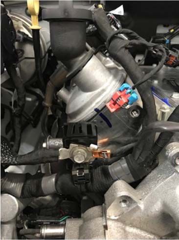
SAFETY PRECAUTIONS
STOP! CAREFULLY READ THE IMPORTANT SAFETY PRECAUTIONS AND WARNINGS BEFORE
PROCEEDING WITH THE INSTALLATION!
Appropriate disassembly, assembly methods and procedures are essential to ensure the personal
safety of the individual performing the kit installation. Improper installation due to the failure to
correctly follow these instructions could cause personal injury or death. Read each step of the
installation manual carefully before starting the installation.
Always wear safety glasses for eye protection.
Place the ignition switch in the OFF position.
Always apply the parking brake when working on the vehicle.
Block the front and rear tire surfaces to prevent unexpected vehicle movement.
Operate the engine only in well-ventilated areas to avoid exposure to carbon monoxide.
Do not smoke or use flammable items near or around the fuel system.
Use chemicals and cleaners only in well-ventilated areas.
Batteries can produce explosive hydrogen gas which can cause personal injury. Do not allow flames,
sparks or flammable sources to come near the battery.
Keep hands and any other objects away from the radiator fan blades.
Keep yourself and your clothing away from moving parts when the engine is running. Do not wear
loose clothing or jewellery that can be caught in rotating or moving parts.
Disconnect both the Negative (-) and Positive (+) Battery Terminal Leads (in this order) to reduce the
risk of electric shock.
VEVF2300-MANUAL – V1.0 Printed April 20, 2020 -9-SECTION A – DISASSEMBLY
The following section will guide you through the disassembly of the stock components. Special care should
be taken to label fasteners and parts that are taken off during this procedure since some will be reused:
1. Cover both fenders with fender covers to protect the vehicle finish.
2. Remove the engine cover. Set this aside as it will not be re-used.
3. Release the fuel system pressure by removing the cap on the front end of the passenger’s side fuel
rail and relieve the pressure by pressing in the centre of the Schrader valve. A rag over the end of
the fuel rail will help contain any fuel that may spill while relieving the pressure.
WARNING: Fuel in the fuel system remains under high pressure even when the engine is not
running. Before working on or disconnecting any of the fuel lines or fuel system components, the
fuel system pressure must be relieved. Failure to do so can result in personal injury.
WARNING: Do not smoke or carry lighted tobacco or open flame of any type when working on or
near any fuel-related components. Highly flammable mixtures are always present and can be
ignited, resulting in personal injury.
4. Disconnect the (+) positive connection to the battery. The battery is located in the boot on the
passenger’s side.
VEVF2300-MANUAL – V1.0 Printed April 20, 2020 - 10 -5. Drain the cooling system coolant and remove the heater inlet & return hoses that route along the
top of the passenger side fuel rail.
6. Disconnect the PCV Fresh Air Inlet tube from the right-hand rocker cover near the top of the cam
cover and disconnect from the clean air tube. Remove hose from the vehicle.
7. Disconnect the brake booster vacuum hose from the port on the brake booster.
8. Remove the Mass Air Flow (MAF) sensor electrical connector from the air box, by pressing the release
tab.
9. Disconnect the induction noise tube from the firewall, undo the bracket holding the tube next to the
ABS module and fuse box. (VF Only)
10. Remove the two fasteners securing the air box assembly to the passenger’s side guard and remove
the entire unit as an assembly with induction hose attached from the vehicle.
VEVF2300-MANUAL – V1.0 Printed April 20, 2020 - 11 -11. Place a rag underneath the fuel supply line at the fuel rail joint. Remove the fuel supply line lock, by
pulling it up off of the supply line. Remove the fuel inlet supply line from the fuel rail using the fuel
line tool supplied. Insert the tool into the female connector and push inward to release the locking
tabs. With the tabs released, remove the supply line from the fuel rail.
12. Remove the fuel supply line from the vehicle by using the same tool that was used in the previous
step and remove the jumper line from the body supply line. This line will not be re-used.
VEVF2300-MANUAL – V1.0 Printed April 20, 2020 - 12 -13. Disconnect the electrical connector from the manifold absolute pressure (MAP) sensor, located
behind the throttle body on the driver’s side.
14. Disconnect the EVAP Purge line from the intake manifold behind the throttle body and from the
EVAP Solenoid on the front of the driver’s side cam cover. Set this aside as it will need to be
modified for re-use.
15. Disconnect the PCV line from the port located on the driver’s side valley plate cover below the MAP
sensor. Disconnect the line from the port on the intake manifold at the opposite end. Set this aside
as it will not be re-used.
16. Disconnect the EVAP body line from the EVAP Solenoid and remove it from the retaining clips
holding it in place. Carefully position this out of the way as it will be re-connected later.
17. Disconnect the eight (8) fuel injector electrical connectors & wires disconnected from the fuel rail.
18. Remove the ten (10) intake manifold mounting bolts and remove the intake manifold and fuel rail
assembly as a complete unit from the vehicle. This hardware will not be reused.
NOTE: If you have not yet checked the DOD plate in your vehicle (refer to page 2) do this now.
19. Clean the intake mounting surfaces and apply tape over the open intake ports to prevent engine
contamination.
20. Rotate the tensioner assembly clockwise and remove the accessory drive belt from the engine.
It will not be re-used.
VEVF2300-MANUAL – V1.0 Printed April 20, 2020 - 13 -21. Remove the tensioner assembly and fasteners. Set the bolts aside as they will be re-used.
23. Remove the bolt circled in the picture below.
#23
#21
24. Remove both the left hand and right side cooling module mounting brackets. Set these aside as one
will be re-used and the grommet from the second will be re-allocated to a new bracket.
VEVF2300-MANUAL – V1.0 Printed April 20, 2020 - 14 -SECTION B – MODIFICATIONS
The following section will guide you through the required modifications of existing components and build-
up of the assemblies used to complete the installation. All of this work can be performed away from the
vehicle.
Throttle Body Removal
1. Remove the four (4) bolts that retain the factory electronic throttle body from the intake manifold
assembly that was previously removed from the engine. Retain the gasket as it will be re-used with
the new supercharger.
EVAP Solenoid Relocation
1. Remove the bolt that secures the EVAP solenoid bracket to the front of the driver’s side cylinder
head. Remove the bolt that retains the wiring and ground wire to the lower bolt hole on the front
face of the driver’s cylinder head.
2. Undo the electrical connection to the EVAP Solenoid and remove the solenoid from the bracket by
pressing down on the centre of the lock mechanism.
3. Bend the anti-rotation tab on the bracket flat as shown below.
VEVF2300-MANUAL – V1.0 Printed April 20, 2020 - 15 -4. Re-install the bracket and position it against the lower mounting hole on the cylinder head. Put the
ground wire on top of this and install the fastener. (Remove the anti-rotation tab off of the ground
eyelet). Torque to 25 Nm. Some paint from the bracket may need to be removed for the wires to
ground correctly to the engine.
5. Re-install the EVAP solenoid onto the top of the bracket in the new mounting position.
6. Connect the electrical connector and EVAP quick connect fitting from the body line. The new
position and wiring routing should now look like this.
VEVF2300-MANUAL – V1.0 Printed April 20, 2020 - 16 -SECTION C – SUBASSEMBLY
Intercooler Low Temperature Radiator (LTR)
1. Position the Low Temp Radiator – (LTR) (HH-8K229) face down on a suitable working surface.
2. Take the two (2) long 12.7mm thick pieces of insulation tape (HH-8K232) found in Hardware Kit F
(HH-HWKF), remove the adhesive backing and position them along the top and bottom surfaces of
the LTR along the edge of the header tanks as shown.
3. Take the two (2) short 4.7mm thick pieces of insulation tape (HH-8K231) found in Hardware Kit F
(HH-HWKF), remove the adhesive backing and place these along the inside surface of the two
mounting brackets.
VEVF2300-MANUAL – V1.0 Printed April 20, 2020 - 17 -4. Install the 1/8” pipe plug (W706310) into the top of the header tank. This can be found in Hardware
Kit F (HH-HWKF). Note – Do not fully tighten at this time. When filling the intercooler system with
coolant, this may need to be removed to help remove trapped air from the system.
EVAP Hose Assembly
1. Remove the 90° quick connect fitting from the EVAP line that was removed from the vehicle.
2. Insert the quick connect fitting into one end of the new EVAP Hose (HH-9G297) found in
Hardware Kit D (HH-HWKD).
VEVF2300-MANUAL – V1.0 Printed April 20, 2020 - 18 -Intake Manifold Assembly
1. Remove the Fuel Charging Assembly (HH-9H487) from the packaging. Carefully place it upside
down onto a clean and sturdy work area.
2. Insert the eight (8) individual intake manifold gaskets (19256623) around each of the intake
manifold runner ports as shown. These can be found in Hardware Kit A (HH-HWKA).
3. Apply some O-ring lubricant onto the new 2 Bar MAP Sensor (90423637) and install into the front of
the intake manifold. Install the M6x16 fastener (W500213). These can be found in Hardware Kit A
(HH-HWKA). Torque to 10 Nm.
VEVF2300-MANUAL – V1.0 Printed April 20, 2020 - 19 -4. Lube the fuel injector O-rings with assembly lube. Install the eight (8) Fuel Injectors
(0280158187) into the fuel charging assembly with the electrical connectors facing outboard.
These can be found in Hardware Kit A (HH-HWKA).
5. Gently place the fuel rail (HH-9F792) over the top of each injector. Ensure that the rear cross over is
routed underneath and behind the coolant tubes on the intake. Seat the fuel rail onto each injector
and then install the four (4) fuel rail mounting bolts (R18020009) found in Hardware Kit A (HH-
HWKA). Torque to 10 Nm.
VEVF2300-MANUAL – V1.0 Printed April 20, 2020 - 20 -6. Install the supercharger sealing gasket (R07060166) as well as the supercharger bypass gasket
(R07060183) into the machined grooves on the upper intake. These can be found in Hardware Kit A
(HH-HWKA).
Note: There is a 1/8” NPT threaded port located in the rear passenger side corner of the upper intake
manifold. This port comes with a plug installed from SLP. This port location was provided as a
manifold vacuum/pressure source for a boost gauge or for vehicles equipped with the active
exhaust option. Fitting not provided.
VEVF2300-MANUAL – V1.0 Printed April 20, 2020 - 21 -Degas Bottle Mounting Bracket
2006+ Degas Bottle Bracket (HH2010-6B634)
1a. VE Vehicles Only - Locate one of the factory cooling module mounting brackets that was
removed during dis- assembly. Remove the rubber grommet from the bracket.
1b. VF Vehicles Only - Locate the Rubber Grommet supplied in the kit parts and fit to the bracket.
2. VE Vehicles Only - Swap the rubber grommet from the original bracket to the new bracket.
VEVF2300-MANUAL – V1.0 Printed April 20, 2020 - 22 -I/C Pump Wiring Harness
1. Remove the Intercooler Pump Wiring Harness (HH-8W501) from Hardware Kit C (HH-HWKC).
-12V Pump
Connector Connector
Lead for
Fuse Tap
+12V
Connector
2a. Connect and secure the Fuse Tap (R18060010) found in Hardware Kit C (HH-HWKC) to the lead for
the fuse tap on the wire harness indicated above.
2b. Use the Mini Fuse Tap if installing to a VE Model or the Micro Fuse Tap if installing to a VF Model
Vehicle
3. Install the 10 amp fuse (08N2483) found in Hardware Kit C (HH-HWKC) into the top location of the
fuse tap.
VEVF2300-MANUAL – V1.0 Printed April 20, 2020 - 23 -SECTION D – INSTALLATION
The following section will guide you through the final installation of the kit into the vehicle. If you
need to stop during any part of the installation, make sure you cover any open ports in the cylinder
heads or intake manifold to prevent foreign material from contaminating your engine.
Intake Manifold and Supercharger Installation
1. Connect the new PCV Fresh Air Hose (HH-6758) to the port on the front corner of the driver’s
side rocker cover. Lay the hose off to the side as it will be connected in a later step.
2. Remove the tape or protective covering from the cylinder heads and clean the cylinder head
to intake manifold mating surfaces.
VEVF2300-MANUAL – V1.0 Printed April 20, 2020 - 24 -3. Carefully place the fuel charging assembly onto the cylinder head mounting surface. NOTE:
Do not use the two tubes at the rear of the intake as handles. Install the ten (10) M6x74.5
intake mounting bolts (N807072). These can be found in Hardware Kit A (HH-HWKA). Install
these fasteners in the positions shown and tighten the sequence in two stages. Stage 1;
torque bolts to 10 Nm. Stage 2; tighten bolts an additional 45 degrees.
#10
#9
#5 #4
#1 #2
#6
#3
#7
#8
4. Connect the eight fuel injector electrical connectors.
5. Remove the supercharger assembly (HH-6F066) from the protective packaging and place on
a workbench or solid flat surface. Remove the protective shipping covers.
VEVF2300-MANUAL – V1.0 Printed April 20, 2020 - 25 -6. Install the supercharger pulley (HH-6K88CP) onto the hub of the supercharger using the five
(5) M6x16 fasteners (W500013) found in Hardware Kit B (HH-HWKB). Apply a small amount
of blue thread locking compound to the bolts, and torque to 10 Nm. (TIP: Torque these
bolts once the FEAD Belt has been installed to keep the Supercharger from rotating).
7. Install the SLP Badge (010036203) and the TVS2300 Badge (010036202) to the supercharger
using the four (4) M4x16 fasteners (940706400) found in Hardware Kit A (HH-HWKA). Apply
a small amount of blue thread locking compound to the bolts and torque to 3 Nm.
8. Connect the supercharger bypass reference vacuum line (R18140001) found in Hardware Kit
D (HH-HWKD) from the port on the bypass actuator to the rear port on the driver’s side of
the supercharger.
9. With the help of an assistant, carefully place the supercharger on top of the intake manifold.
Ensure that the supercharger is fully seated on the intake mounting dowels.
VEVF2300-MANUAL – V1.0 Printed April 20, 2020 - 26 -10. Install the eight (8) M8 x 53 fasteners (N808130) into the supercharger mounting holes.
These can be found in Hardware Kit A (HH-HWKA). Torque fasteners in three steps; 10Nm,
20Nm and 30Nm in the sequence shown.
#5 #1 #4 #8
#7 #3 #2 #6
11. Install the factory throttle body gasket into the machined grooved of the supercharger and
mount the throttle body using the four (4) M6 x 40 fasteners (R18020004). These parts can
be found in Hardware Kit A (HH-HWKA). Torque the fasteners to 10 Nm.
12. Re-connect the electrical connector for the Throttle Body. Re-adjust the wiring harness in
the bundle if more slack is need to make the connection.
VEVF2300-MANUAL – V1.0 Printed April 20, 2020 - 27 -13. Connect the new PCV Hose (DMHCP-3312) to the rear port on the passenger side rocker
cover. Place a ½” clamp (2UTG7) onto each end of the new Brake Booster Hose (DMHCP-
5429) and connect to the port on the brake booster. These can be found in Hardware Kit D
(HH-HWKD).
PCV
Brake Booster
NOTE: Some vehicles will have a cap (A) on this port on the cam cover. Remove this cap
and place it on the open port (B) of the tube coming from the engine valley plate,
underneath the front of the intake.
A
B
VEVF2300-MANUAL – V1.0 Printed April 20, 2020 - 28 -14. Connect the opposite end of the PCV Hose to the lower port of the supercharger and the
Brake Booster Hose to the top port of the supercharger on the driver side.
Brake Booster
PCV
15. Connect the new EVAP hose (HH-9G297) to the quick connect fitting on the EVAP solenoid
and route to the forward port on the passenger side of the supercharger.
VEVF2300-MANUAL – V1.0 Printed April 20, 2020 - 29 -16. Connect the fuel supply line (CP92266218) to the inlet of the fuel rail and the body side fuel
line. Secure the factory locks into position on each end.
VEVF2300-MANUAL – V1.0 Printed April 20, 2020 - 30 -FEAD Assembly
Early Water Pump Supplement (Driver’s Side Top Outlet).
1. Install new Heavy Duty Tensioner to Water Pump.
2. Undo Power Steering Reservoir Bracket from Passenger’s Side Cylinder Head. Relocate
using top hole only and re-route wires accordingly.
3. Very carefully bend Steam Pipe towards Power Steering Reservoir to allow clearance for belt.
VEVF2300-MANUAL – V1.0 Printed April 20, 2020 - 31 -Early Water Pump Supplement (Driver’s Side Top Outlet). - CONTINUED
4. Remove bottom Alternator Bolt and set aside. You will no longer need this bolt. Using new
Idler and M10x120 Bolt supplied, fit new idler in place and tighten.
5. Note: Air Conditioning Line may need to be slightly repositioned depending on Vehicle.
6. Fit Belt as per diagram below.
VE V8 EARLY- 6PK2495-6PK2500
Note: If required, you can trim the longer Power Steering Hose by 15mm, this will prevent
the hose from kinking.
VEVF2300-MANUAL – V1.0 Printed April 20, 2020 - 32 -FEAD Assembly
1. Install the new Tensioner Assembly (12569301) provided using the factory mounting bolts.
Torque to 25 Nm.
2. Install the new Idler Mounting Bracket (HH-8B653) to the front of the intake manifold and
water pump housing using three (3) washers (M8), two (2) M8 x 45 mm bolts
(HHCS8X1.25X45) and one (1) M8 x 95 mm bolts (HHCS8X1.25X95) from Hardware Kit B (HH-
HWKB). Torque the bolts to 25 Nm.
3. Install the new Idler Pulley (08567-32) onto the machined posts of the Upper FEAD Bracket.
Secure the pulley using one (1) M8 x 1.25 x 28mm idler bolt (R18020060) found in Hardware
Kit B (HH-HWKB). Torque bolts to 25 Nm.
M8x45
M8x95
VEVF2300-MANUAL – V1.0 Printed April 20, 2020 - 33 -4. Route the new FEAD Belt provided per the schematics shown.
VE V8 LATE- 6PK2480 VF V8 - 6PK2375
Wiring
1. Route the new TMAP / MAF Harness (HH-12A690) found in Hardware Kit C (HH-HWKC)
underneath the new idler bracket and connect the vehicle MAP sensor electrical connector
to the mating electrical connector on the new TMAP / MAF Harness.
VEVF2300-MANUAL – V1.0 Printed April 20, 2020 - 34 -2. Connect the new harness to the TMAP Sensor, located below the snout of the supercharger.
3. Route the remaining length of the new harness along the top of the upper radiator hose
and secure using zip ties. Connect the vehicle wiring harness MAF sensor connector to the
new harness.
VEVF2300-MANUAL – V1.0 Printed April 20, 2020 - 35 -Intercooler Pump & Wiring Mounting
1. Remove the nut holding the sway bar mount to the sub frame of the vehicle on the driver’s
side.
2. Install the P-Clip (F523-036CA) to the bracket using M8x20 Bolt with 2x washer and 1x nyloc
nut, do not tighten at this point. Install the bracket on to the sway bar mount bolt, replace
the nut and tighten the bracket.
VEVF2300-MANUAL – V1.0 Printed April 20, 2020 - 36 -3. Insert the intercooler pump (F8YZ-8501) through the P-Clip oriented as shown.
NOTE: Applying some O-ring lubricant to the p-clip will aid in sliding the pump in easily.
4. Connect the I/C Pump wiring harness (HH-8W501) to the I/C Pump.
5. Route the harness up along the frame rail to the fuse box. Secure wiring off using zip ties
supplied in kit.
VEVF2300-MANUAL – V1.0 Printed April 20, 2020 - 37 -6. Remove the 20 amp fuse from position #37 or anywhere with ignition power and place it
into the lower location of the fuse jumper on the I/C Pump Wiring Harness. Place the fuse
tap into Fuse Box location.
7. Secure the relay of the new harness in front of the fuse box under the negative terminal
using the supplied M6 x 16 Bolt and Nut. This can be found in Hardware Kit C (HH-HWKC).
Remove the loom clip against the body to gain access to mount the replay in position.
Disregard the clip it will no longer be used
VEVF2300-MANUAL – V1.0 Printed April 20, 2020 - 38 -8. Connect the Positive (+12V) eyelet on the I/C Pump Harness to the Positive post on the rear
of the fuse box. Wirers be grouped using zip ties or shorten to length if desired.
9. Connect the Negative (-12V) eyelet on the I/C Pump Harness to the Ground bolt in front of
the fuse box utilizing the factory ground location.
VEVF2300-MANUAL – V1.0 Printed April 20, 2020 - 39 -10. Connect the yellow wire to the Fuse jumper that was installed in the fuse box back in step 6
11. A small notch will need to be made in the fuse box lid to allow the yellow wire through and
for the lid to fit back correctly
VEVF2300-MANUAL – V1.0 Printed April 20, 2020 - 40 -Intercooler Radiator Assembly Mounting
1a. VE Vehicles Only - Remove under tray from Vehicle and front bumper bar if it hasn’t already
been done previously. From underneath the vehicle cut two holes into the lower close out
panel using a 2” holesaw / air saw or equivalent tool for routing of the intercooler hoses. Use
the cooler outlets to mark where to drill in the plastic. (Raise the vehicle on a lift or jack
stands if available to ease installation).
1b. VF Vehicles Only - Remove intrusion beam with in fill panel and side ducts, Cut the infill
panel back to the first moulded rib line, cut-off wheel works well for this step.
2. Remove both Radiator support brackets for these next steps (if not already removed). The
passenger side bracket will be reinstalled back to the vehicle once the following steps are
complete.
VF Bracket Picture
VEVF2300-MANUAL – V1.0 Printed April 20, 2020 - 41 -3. Push the cooling module towards the engine and lower the new LTR (HH-8K229) in front of
the A/C Condenser. Hang the new LTR on the A/C Condenser and position.
4. Install the driver side cooling module retaining bracket and secure using the factory bolt.
Torque to 10 Nm.
VEVF2300-MANUAL – V1.0 Printed April 20, 2020 - 42 -Intercooler Degas Bottle Mounting
1a. VE Models Only – Use the radiator support bracket supplied in the kit (CP92265004) and fit
to the upper radiator support panel on the vehicle. Remove the existing rubber from the
radiator mount flip it upside down and install into the new degas bottle mount.
1b. VF Models Only – Use the radiator rubber supplied in kit (CP2116166) and mount in Degas
Bottle mount as per photo.
2. Install the Degas Bottle Mounting Bracket assembly into position. Install the bracket to the
body using the original bolt.
3. Install the Degas Bottle (R07070007) onto the mounting bracket and secure using the two
(2) M6 nuts (W520412) found in Hardware Kit F. Torque to 10 Nm.
VEVF2300-MANUAL – V1.0 Printed April 20, 2020 - 43 -4. Install the Degas Bottle Cap (9C3Z-8101) found in Hardware Kit F (HH-HWKF) at this time to
keep debris out of the system.
VEVF2300-MANUAL – V1.0 Printed April 20, 2020 - 44 -Intercooler Hose Routing
1. Connect the Intercooler LTR Outlet hose (HH-8D030) to the driver side turret on the rear of
the intake manifold. Secure the hose using one (1) ¾” constant tension clamp (CT19X12-BO)
from Hardware Kit E (HH-HWKE). Route hose along the side of fender, behind vehicle body
lines, and connect the opposite end to the outlet of the LTR on the driver side of the vehicle
using one (1) ¾” constant tension clamp (CT19X12-BO).
VEVF2300-MANUAL – V1.0 Printed April 20, 2020 - 45 -2. Connect the I/C Pump to LTR Hose (HH-8K236) from the outlet of the I/C Pump to the inlet
of the LTR. Secure the hose using one (1) ¾” constant tension clamp (CT19X12-BO) from
Hardware Kit E (HH-HWKE). Route the hose underneath the cooling module and connect
to the port on the LTR using (1) ¾” constant tension clamp (CT19X12-BO).
3. Connect the Degas Reservoir to I/C Pump Inlet Hose (HH-8D029). Secure the hose using one
(1) ¾” constant tension clamp (CT19X12-BO) from Hardware Kit E (HH-HWKE) at the pump.
Route and connect to the port on the Degas Reservoir using (1) ¾” constant tension clamp
(CT19X12-BO).
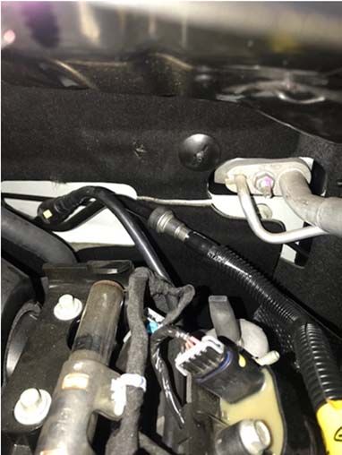
VEVF2300-MANUAL – V1.0 Printed April 20, 2020 - 46 -4. Connect the CAC to Degas hose (HH-8D031) from the turret on the passenger side of the
intake to the inlet port of the Degas Reservoir. Secure the hose using one (1) ¾” constant
tension clamp (CT19X12-BO) from Hardware Kit E (HH-HWKE) at the pump. Route the hose
underneath the fuel supply line and connect to the port on the Degas Reservoir using (1) ¾”
constant tension clamp (CT19X12-BO).
Note: Route all intercooler hoses very carefully. It is critical for intercooler performance that
these hoses are not kinked once installed into the vehicle.
VEVF2300-MANUAL – V1.0 Printed April 20, 2020 - 47 -Air Induction System
1. Install aftermarket air box and secure using the factory fasteners that were removed.
2. Install Air Filter and Filter Adapter to the air box using three 1/4-20 x ½” Button Head Screws
and three 1/4” Flat Washers Provided.
3. Mount Airflow Meter to Air Filter Adapter using the Airflow Meter Coupler. Please note the
Airflow Meter Coupler is slightly larger than the two Throttle Body Couplers provided in the
kit.
4. Attach Plastic Angled Adapter to Airflow Meter using Throttle Body coupler (25180042)
VEVF2300-MANUAL – V1.0 Printed April 20, 2020 - 48 -5. Install the new Throttle Body coupler (25180042) over the end of the clean air tube
(210125212).
3. Place clamps (210144126) onto each end of the new Bellows Coupler (100064010) and
secure the Coupler to the opposite end of the clean air tube.
VEVF2300-MANUAL – V1.0 Printed April 20, 2020 - 49 -4. Install the new Clean Air Tube assembly over the throttle body and the angled joiner.
Secure the clamps on both ends of the clean air tube. Torque all clamps to 10 Nm.
5. Connect the new MAF Harness to the MAF Sensor.
VEVF2300-MANUAL – V1.0 Printed April 20, 2020 - 50 -6. Connect the PCV Fresh Air hose to the port on the Clean Air Tube. VEVF2300-MANUAL – V1.0 Printed April 20, 2020 - 51 -
Final Assembly

1.     Fill the intercooler system through the degas bottle. The coolant should be approximately
       one inch below the top of the cap. Install the degas bottle cap (9C3Z-8101) and tighten
       when full.

       Important: The coolant system can trap a large amount of air. It is very important to verify
       that the air is purged and that coolant is flowing properly through the systems. SLP
       recommends vacuum filling the system to properly evacuate the trapped air. If a vacuum fill
       system is not available, the plug on the top tank of the Low Temp Radiator can be removed
       to purge any air bubbles. Re-install plug once the coolant begins to reach the plug fitting.

2.     Inspect all under hood wiring harnesses for potential interference issues. Use zip ties to
       safely position the harness away from any areas of concern. Ensure the supercharger bypass
       has adequate clearance around the actuator

3.     Once the ECU / PCM has been successfully re-calibrated, start the engine and check for
       unusual noises, dash service lights, and unusual operation. If problems are detected,
       immediately stop the engine or vehicle, diagnose and repair the problem.

VEVF2300-MANUAL – V1.0                   Printed April 20, 2020                                 - 52 -
APPENDIX A: Upgraded DOD PLATE INSTALLATION
This step is only necessary if you had the incorrect DOD plate shown on page 2 of this manual.
1. Install the manifold (451) with gasket.
2. Install the manifold bolts (506) and tighten to 25 Nm using a centre out pattern.
3. Remove the oil pressure sensor/switch from the old cover and install into the new cover.
Use read sealer on threads and tighten the engine oil pressure sensor to 20 Nm.
VEVF2300-MANUAL – V1.0 Printed April 20, 2020 - 53 -WARNING
1. DO NOT ATTEMPT TO OPERATE VEHICLE UNTIL ALL COMPONENTS ARE
INSTALLED AND COMPLETE. SUPERCHARGER KITS EXTRUDE A HUGE AMOUNT OF
HORSEPOWER FROM A STOCK ENGINE THEY ARE NOT INTENDED FOR
CONTINUOUS OR EXTREME PERIODS OF MAXIMUM POWER OUTPUT. IT IS NOT
OUR INTENTION TO CREATE RACE PROVEN HORSEPOWER BUT LEISURE ENDURING
SYSTEMS.
2. WARRANTY POLICY FOR 12 MONTHS, UNLIMITED KILOMETRES COVERS FAULTY
COMPONENTS PROVIDED IN SUPERCHARGER KIT. POLICY DOES NOT INCLUDE
LABOUR TO REPLACE FAULTY PARTS.
3. THE RESPONSIBILITY OF ADR COMPLIANCE AND INSURANCE FOR THIS KIT FITTED
TO A VEHICLE THAT IS ROAD REGISTERED AND DRIVEN IS THE RESPONSIBILITY OF
THE VEHICLE OWNER.
4. RESPONSIBILITY FOR CORRECT FITMENT OF THE KIT IS THE REPONSABILITY OF THE
FITTER.
5. DAMAGES TO VEHICLE OR SURROUNDS IS THE RESPONSIBILITY OF THE VEHICLE
OWNER. PROVIDED THE KIT FITMENT IS CORRECT, ACCORDING TO THIS MANUAL.
GET OUT THERE & ENJOY...
VEVF2300-MANUAL – V1.0 Printed April 20, 2020 - 54 -You can also read