Underwater In Situ Local Heat Treatment by Additional Stitches for Improving the Weldability of Steel
←
→
Page content transcription
If your browser does not render page correctly, please read the page content below
applied
           sciences
Article
Underwater In Situ Local Heat Treatment by
Additional Stitches for Improving the Weldability
of Steel
Jacek Tomków 1, *         and Anna Janeczek 2
 1    Department of Materials Engineering and Welding, Faculty of Mechanical Engineering, Gdańsk University
      of Technology, G. Narutowicza 11/12, 80-233 Gdańsk, Poland
 2    Department of Materials Engineering and Welding, Gdańsk University of Technology, G. Narutowicza 11/12,
      80-233 Gdańsk, Poland; ania.janeczek96@gmail.com
 *    Correspondence: jacek.tomkow@pg.edu.pl; Tel.: +48-58-347-1863

 Received: 13 February 2020; Accepted: 4 March 2020; Published: 6 March 2020

 Abstract: In this paper the influence of in situ local heat treatment performed by additional stitches
 on the weldability of high-strength low-alloy (HSLA) S355J2C+N steel was tested. The investigated
 steel is characterized by high susceptibility to cold cracking. It is necessary to find a method to
 improve the quality of welded joints. The local heat treatment was applied as an effect of bead-on
 plate welding made on the face of a Tekken test joint. The specimens were made by the use of covered
 electrodes in the water environment. For testing weldability, Tekken test specimens were made.
 Then, the different number of the pad welds with different overlapping were laid on the face of
 the tested welds. Non-destructive (NDT) visual and penetrant tests were undertaken. During the
 NDT, imperfections like shape mistakes and spatters were found. Then, metallographic macro- and
 microscopic testing were performed. The macroscopic observations proved that water environment
 can generate imperfections like cracking and pores. However, for specimens with additional stitches
 the number of imperfections decreased. Microscopic tests proved that the proposed technique
 affected the structure of the heat-affected zone (HAZ). The specimens without the application of
 additional stitches are characterized by brittle bainitic and martensitic structure. Specimens, in which
 the additional stitches were applied, contain tempered martensite, fine ferrite and fine pearlite in
 their HAZ. It was also observed that the number of cracks decreased for in situ local heat-treatment
 specimens. The final step was Vickers HV10 hardness measurement. These measurements confirmed
 previous results. The heat from additional stitches affected the steel by significantly decreasing the
 hardness by 80–100 HV10. The results of experiments showed that the heat from pad welds provided
 microstructural changes in heat-affected zones and a decrease in the susceptibility to cold cracking,
 which results in improvement in the weldability of HSLA steel in wet welding conditions.

 Keywords: underwater wet welding; high-strength low-alloy steel; cold cracking; bead-on plate
 welding; metallographic testing

1. Introduction
     High-strength low-alloy (HSLA) steels are used in many types of structure. In comparison to
conventional low-carbon steels, HSLA steels are characterized by favorable strength-to-weight ratio.
That results in a lower cost of structures [1]. The usage of these materials has been changing in recent
years. Earlier, they have been used only in the air. Now, they are the most common materials used for
marine structures, which are characterized by direct contact with water [2]. The following application
may be classified as an example of marine and offshore structures:

Appl. Sci. 2020, 10, 1823; doi:10.3390/app10051823                                www.mdpi.com/journal/applsci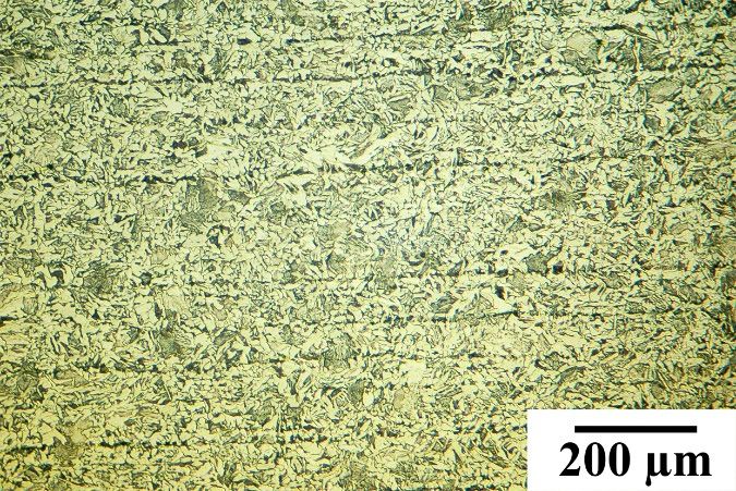
Appl. Sci. 2020, 10, 1823                                                                           2 of 16

                                •     bridges [3];
                                •     pipelines [4,5];
                                •     wind turbines [6];
                                •     ships [7];
                                •     wharfs [8].

                                      Defects could occur in marine and offshore structures, so it is important to find the proper
                                strengthening technique [9]. The technique could be applied during preparation of the structures.
                                The laying of the coating is widely used to improve the surface and properties of the substrate. Coatings
                                are widely deposited by pad welding [10] and arc spraying [11]. The other method of improving the
                                properties of the material surfaces could be the use of the ceramic brush tools to change the roughness.
                                High roughness can generate the notch effect, which can cause a cracking effect [12]. Also, welding
                                imperfections may occur in offshore constructions. During preparation of the structure, numerical
                                analysis can be used for prediction the potential location of the failure [13,14]. Welding of HSLA
                                steels in the air is a well-known process. There is a lot of literature addressing concerns about joining
                                of these group of materials by different welding methods. To improve the quality of welded joints,
                                the modeling of temperature field during multi-pass gas metal arc welding (GMAW) surfacing or
                                rebuilding of steel elements taking into account that the heat of the deposit metal could be applied [15].
                                The cooling time between temperatures 800 ◦ C and 500 ◦ C (t8/5) is a factor with high influence on the
                                quality of the joint [16]. This factor is responsible for microstructural transformations in a welded
                                joint. There are HSLA steels in which the preheating process generates positive effects and provides
                                increasing t8/5, which is responsible for decreasing the occurrence of the welding imperfections [17].
                                During joining in the air, the quality of a welded joint also depends on welding parameters [18] and
                                filler material storage conditions [19].
                                      However, offshore structures may undergo failures. Damaged areas can be located under the
                                water surface, which determines the necessity of repairs in water conditions. There are three methods
                                of underwater welding [20–23]:

                                •     dry welding (hyperbaric and isobaric)—the welding area and welder are isolated from the
                                      environment by a special chamber;
                                •     local dry cavity welding—the welding area is in situ isolated from environment, the steel plates
                                      and welder are in direct contact with environment;
Downloaded from mostwiedzy.pl

                                •     wet welding—the welding area and welder are in direct contact with the water environment.

                                     The method of underwater welding used most often is wet welding. The most common methods
                                of wet welding are flux-cored arc welding (FCAW) [24] and manual metal arc welding (MMA) [25,26].
                                The water, as a welding environment, generates problems, which have a negative influence on the
                                quality of the joint. The biggest negative phenomenon during wet welding is presence of high diffusible
                                hydrogen content in deposited metal. The results of the measurements of diffusible hydrogen in
                                deposited metal ranged from 32.61 to 39.95 mL/100 g for specimens welded in air and from 51.50
                                to 61.34 mL/100 g for specimens made in the water [27]. This chemical element is a factor with
                                significant impact on the properties of welded joints. A phenomenon of hydrogen embrittlement is
                                characteristic for low-carbon structural steel also in the air [28,29]. This type of embrittlement can
                                occur even with the cathodic protection conditions [30]. In an air environment, the modeling of a
                                hydrogen-inducted delayed intergranular fracture in high strength steels can be used [31]. However,
                                the prediction of diffusible hydrogen content in deposited metal, in a water environment, is impossible
                                due to unpredictable process conditions, which change during welding. These changes result from the
                                instability of the welding arc in the water, which is the other problem in this environment. Wang et al.
                                stated that ultrasonic wave-assisted during underwater FCAW welding has the potential to control the
                                dynamic bubble and then improve arc stability [32]. Xu et al. [33] proved, that droplet has significant
                                influence on the stability of underwater welding process. Chen et al. [34] stated also that ultrasonic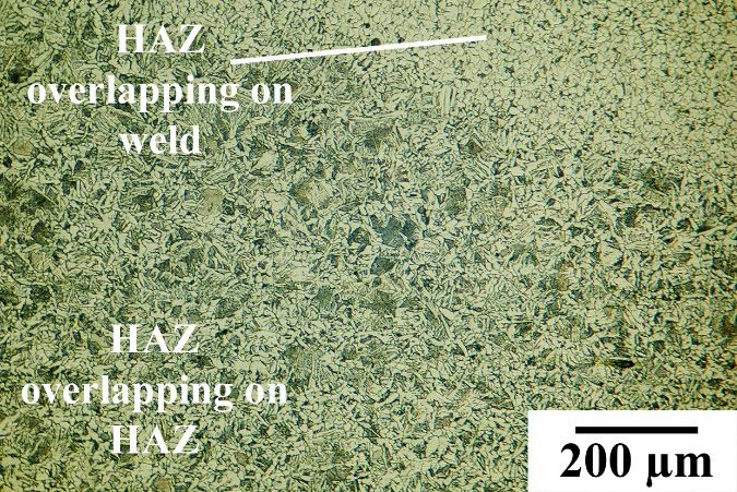
Appl. Sci. 2020, 10, 1823                                                                             3 of 16

                                energy decreases the porosity and diffusible hydrogen content, which can improve the quality of
                                underwater welded joints.
                                      Problems of underwater wet welding generate the high susceptibility of HSLA steel to cold
                                cracking. The cold cracks can occur in the welds and in the heat-affected zone (HAZ) near the fusion
                                line [35].
                                      There are a couple of methods which provide to decreasing the susceptibility to cold cracking
                                of underwater wet-welded joints. It was proved that welding with austenitic consumables, which
                                provides welds with a good plasticity, can reduce the susceptibility to cold cracking. The temper bead
                                welding can also decrease the number of cold cracks in pad welds, made in the water [25]. In previous
                                experiments the bead sequence was investigated. It was stated that a proper bead sequence during
                                underwater wet welding can contribute to decreasing the hardness, tempering the HAZ and reducing
                                the number of cracks in the area of pad welds [36]. A further method reducing the susceptibility to
                                cold cracking is submerged-arc welding applied to marine steels. Han et al. proved, that this method
                                can also reduce the tendency to corrosion of underwater welded joints [37]. Wang et al. proposed
                                welding with higher heat input, which provides a large possibility for a better protective effect and a
                                larger weld penetration [38]. Another method for improving the quality of underwater welded joints
                                is modification of filler materials. Menezes et al. [39] proposed silicate and polymer agglomerated
                                electrodes, which caused higher arc voltage values in comparison to the conventional electrode with
                                the same polarity. This may contribute to decreasing of the number of cracks in the welded joints,
                                which results from lower diffusible hydrogen content in the deposited metal.
                                      The use of traditional heat treatment possibilities is very limited in water due to the negative
                                influence of the environment. Zhang et al. [40] proposed real-time induction heating during wet FCAW
                                welding. Authors stated that the addition of induction heating could reduce the cooling rate of the
                                joint in a water environment to improve the microstructural properties of the joint. The content of
                                brittle structures such as martensite and bainite decreased while the proeutectoid ferrite and acicular
                                ferrite phases increased. However, the induction heating process caused major problems with the
                                stability of the welding arc. This can affect the quality of the welded joints. The local heat treatment as
                                an effect of multiple passes has a positive effect in HSLA steels in air [41]. However, this method has
                                not been verified sufficiently in a water environment.
                                      The aim of this research was to study the influence of in situ local heat treatment on the weldability
                                of high-strength low-alloy S355J2C+N steel. As a method for improving the weldability of steel
                                local heat treatment, provided by the heat from additional stitches, was chosen. Weldability tests are
Downloaded from mostwiedzy.pl

                                commonly used to evaluate the possibilities of the welding in the air for different materials [42,43],
                                and in the water [35]. A Tekken weldability test was chosen for investigation. This test allows
                                assessment of the weldability for a butt-welded joint. On the basis of performed tests [44], it was
                                concluded that investigated S355J2C+N steel is characterized by good weldability during welding
                                in the air and poor in underwater conditions. S355J2C+N steel is widely used in offshore structures,
                                which might be needing a repairs in the water. To the best of the author’s knowledge, there is no
                                research in the literature that provided detailed discussion on the improvement the weldability of a
                                HSLA steel butt-welded joint made in the wet welding conditions.

                                2. Materials and Methods

                                2.1. Used Materials
                                     The HSLA S355J2C+N steel (16 mm thick) was chosen as a base material (BM) for welding.
                                The chemical composition of investigated steel has been analyzed by the emission spectrometry
                                method with spark excitation. As a filler material, ISO 2560-A: E 38 0 R11 [45] rutile electrodes (4.0
                                diameter) were used, which provide welds with a good plasticity, which contributes to decreasing
                                susceptibility to cold cracking. The chemical composition of the used materials are presented in Table 1.
                                The mechanical properties as yield point (Re ) and tensile strength (Rm ) of filler materials should be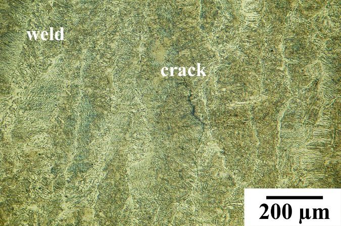
Appl. Sci. 2020, 10, 1823 4 of 16
Appl. Sci. 2020, 10, x FOR PEER REVIEW 4 of 17
equal or greater than the properties of BM [41]. However, the filler material is characterized by a higher
value of elongation
characterized (A5 ), to
by a higher decrease
value the susceptibility
of elongation to cold cracking
(A5), to decrease [25]. The mechanical
the susceptibility properties
to cold cracking [25].
of the
The used materials
mechanical are listed
properties inused
of the Tablematerials
2. are listed in Table 2.
Table 1. Chemical composition of used materials wt. %.
Table 1. Chemical composition of used materials wt. %.
Material C Si Mn P Cr Mo Ni Cu V CeIIW 1
Material C Si Mn P Cr Mo Ni Cu V CeIIW 1
S355J2C+N in
S355J2C+N in accordance
accordance to
0.20
to control analysis 0.200.50 0.50 1.10 1.10 0.020.02 0.02
0.02 0.001
0.001 0.001
0.001 0.02
0.02 0.005
0.005 0.386
0.386
control analysis
E 38 0 R 11 electrodes
E 38deposit
0 R 11 in
electrodes
accordancedeposit
to in
0.07 0.070.44 0.44 0.55 0.55 0.010.01 0.04
0.04 - - - - 0.05
0.05 - - - -
accordance to manufacturer
manufacturer data data
1 Ce
1 Ce IIW— carbon
IIW equivalent
—carbon equivalentby
byInternational Instituteofof
International Institute Welding.
Welding.
Table 2.
Table Mechanicalproperties
2. Mechanical propertiesof
ofused
used materials
materials in
in accordance
accordance to
to manufacturer
manufacturer data.
data.
Material
Material YieldPoint,
Yield Point,ReR(MPa)
e (MPa) Tensile Strength,RR
Tensile Strength, (MPa)
m m(MPa) Elongation, AA
Elongation, 5 (%)
5 (%)
S355J2C+N
S355J2C+N min.355
min. 355 470–630
470–630 17–22
17–22
EE38
3800RR1111electrodes deposit
electrodes deposit 503
503 538
538 2626
2.2.
2.2. Welding
WeldingProcedure
Procedure
In accordancewith
In accordance withEN-ISO
EN-ISO 17642-2
17642-2 [46] [46] the Tekken
the Tekken weldability
weldability test wastest wasforchosen
chosen for the
the experiment.
experiment.
This test enables assessment of susceptibility to cold cracking in all joint areas. The Tekken test isThe
This test enables assessment of susceptibility to cold cracking in all joint areas. one
Tekken test is one tests,
of the weldability of thewhich
weldability tests, which
is characterized by is characterized
high by high
thermal severity. thermal
This severity.
test was chosenThis test
because
was chosen
it allows us because
to study iteven
allows us to
a small studyofeven
impact a small
factors impact of factors
on weldability. For theon weldability.
experiment, sixFor the
Tekken
experiment, six Tekken
test were prepared. Thetest were
upper prepared.
surfaces The
of all upper surfaces
specimens of all 0.5
were placed specimens
m belowwere placedsurface.
the water 0.5 m
below the waterview
The schematic surface. The
of the schematic
Tekken view of
specimens the Tekkeninspecimens
is presented Figure 1. is presented in Figure 1.
Downloaded from mostwiedzy.pl
Figure 1.
Figure Schematic illustration
1. Schematic illustration of
of the
the Tekken
Tekken test specimen
specimen.
In the
In the first
first step
step of
ofinvestigations,
investigations,the theTekken
Tekken butt
buttwelded
welded joints were
joints performed.
were performed. TheThewelding was
welding
carried out in the flat position in accordance to EN ISO 17642-2 standard
was carried out in the flat position in accordance to EN ISO 17642-2 standard [46]. In the next step[46]. In the next step five of
the Tekken specimens were modified. On the surface of the prepared butt
five of the Tekken specimens were modified. On the surface of the prepared butt welded joints, the welded joints, the additional
stitches were
additional laid immediately
stitches after preparation
were laid immediately of Tekken joints,
after preparation to check
of Tekken the influence
joints, to check theof the proposed
influence of
technique on the HSLA steel weldability in wet-welding conditions.
the proposed technique on the HSLA steel weldability in wet-welding conditions. The in situThe in situ heat treatment was an
heat
effect of the heat impact generated by the process of welding of additional stitches.
treatment was an effect of the heat impact generated by the process of welding of additional stitches. They were laid in
the same
They were direction
laid in asthethe Tekken
same test weld,
direction within
as the the maximum
Tekken test weld,time of two
within theminutes
maximum aftertime
completion
of two
of the previous welding process. The scientific hypothesis stated that this
minutes after completion of the previous welding process. The scientific hypothesis stated that modification causes changes
this
in microstructure
modification causesin changes
heat affected zone (HAZ), which
in microstructure in heatdecreases
affected the zonehardness.
(HAZ), which The specimens
decreaseswere the
modified by applying one, two or three additional stitches to the face of the
hardness. The specimens were modified by applying one, two or three additional stitches to the face Tekken weld. The stitches
were
of thewelded
Tekkenwith weld.different distance
The stitches between
were welded axes of the
with stitchesdistance
different calculated as percentage
between axes of overlapping.
the stitches
calculated as percentage overlapping. During the process, the welding arc was unstable,constant
During the process, the welding arc was unstable, which produces difficulties in keeping the which
welding speed
produces and planned
difficulties in keepingoverlapping
the constant of the stitches.
welding speedOne andof planned
the reasons was limited
overlapping of thevisibility
stitches.of
the welding
One area, which
of the reasons was disturbed the process
limited visibility of welding.
of the weldingThese area, factors
which are typical for
disturbed the underwater
process of
welding. These factors are typical for underwater wet-welding processes [25,27,36]. The welding
parameters are presented in Table 3. The additional stitches were welded with higher heat input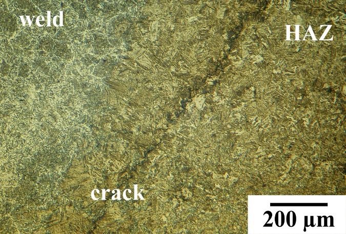
Appl. Sci. 2020, 10, 1823                                                                                          5 of 16

                                wet-welding processes [25,27,36]. The welding parameters are presented in Table 3. The additional
                                stitches   were
                                   Appl. Sci.       welded
                                              2020, 10,        withREVIEW
                                                        x FOR PEER  higher heat input values in accordance with the literature proceedings
                                                                                                                                   5 of 17 [25].
                                The schematic view of cross-sections of the tested area of each specimen is shown in Figure 2.
                                   values in accordance with the literature proceedings [25]. The schematic view of cross-sections of the
                                   tested area of each specimenTable
                                                                is shown  in Figure
                                                                      3. Welding    2.
                                                                                 conditions  for tested specimens.

                                                  Specimen No.       Table  3.No.
                                                                       Stitch WeldingOverlapping
                                                                                     conditions for
                                                                                                 (%)testedIspecimens.
                                                                                                            (A)      U (V)            ql (kJ/mm)
                                                            1               1                  -              180        26.3            0.60
                                                            Specimen No.   Stitch No.   Overlapping (%)   I (A) U (V)    ql (kJ/mm)
                                                                 1          1 1                --          180184 26.3   26.00.60        0.92
                                                            2
                                                                            2 1               100
                                                                                                -          184200 26.0   28.00.92        0.91
                                                                 2
                                                                            1 2               100
                                                                                               -           200184 28.0   27.30.91        0.76
                                                            3
                                                                            2 1               90-          184200 27.3   27.00.76        0.86
                                                                 3
                                                                            1 2                90
                                                                                               -           200188 27.0   25.00.86        0.80
                                                            4
                                                                 4          2 1               80-          188196 25.0   30.00.80        0.95
                                                                                2              80          196    30.0       0.95
                                                                            1                  -              180        25.0            0.68
                                                            5               2 1                 -
                                                                                              100          180200 25.0   29.00.68        0.65
                                                                 5          3 2               100
                                                                                              100          200200 29.0   28.80.65        0.64
                                                                                3             100          200    28.8       0.64
                                                                            1                  -              180        27.3            0.59
                                                                                1               -          180    27.3       0.59
                                                                            2                 100             200        27.5            0.81
                                                            6
                                                                 6          3 2               100
                                                                                              100          200200 27.5   27.80.81        0.97
                                                                            4 3               100
                                                                                              10           200204 27.8   28.00.97        0.90
                                                                                4              10          204    28.0       0.90

                                                                                                                         (a)

                                                                                                                         (b)
Downloaded from mostwiedzy.pl

                                                                                                                         (c)

                                                                                          Figure 2. Cont.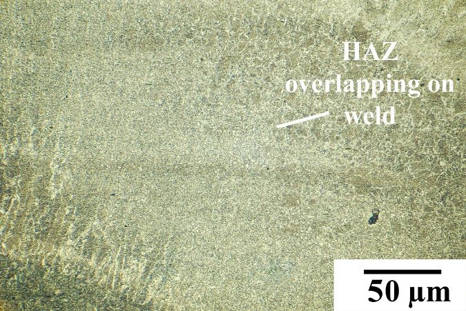
Appl. Sci. 2020, 10, 1823 6 of 16
Appl. Sci. 2020, 10, x FOR PEER REVIEW 6 of 17
(d)
(e)
(f)
Figure 2. The
Figure schematic
2. The view
schematic viewofofcross-sections of tested
cross-sections of testedareas:
areas:(a)(a) Specimen
Specimen 1; Specimen
1; (b) (b) Specimen
2; (c) 2; (c)
Specimen 3; (d)
Specimen Specimen
3; (d) 4; 4;
Specimen (e)(e)Specimen
Specimen5;5; (f)
(f) Specimen
Specimen 6.6.
2.3. Methodology of the
2.3. Methodology Tests
of the Tests
Tekken joints
Tekken were
joints tested
were by by
tested non-destructive
non-destructive tests
tests(NDT)
(NDT)andanddestructive
destructive tests (DT).
(DT). The
Thefirst
first step
was NDT:
step wasvisual
NDT:testing
visual(VT) in accordance
testing with thewith
(VT) in accordance ENthe ISOEN 17637:2017 [47] standard
ISO 17637:2017 and penetrant
[47] standard and
Downloaded from mostwiedzy.pl
penetrant
testing (PT) in testing
accordance(PT) with
in accordance
the EN ISO with the EN ISO
3452-1:2013 3452-1:2013
standard standard
[48]. After NDT[48]. After NDT
specimens were cut
specimens
1 1 were3cut for DT at ¼, ½, and ¾ of joint length of each specimens, and from each specimen,
for DT at 4 , 2 , and 4 of joint length of each specimens, and from each specimen, two testing specimens
weretwo testing specimens were chosen. The prepared cross-sections were grinded, polished, and etched
chosen. The prepared cross-sections were grinded, polished, and etched by Nital 4%. Then,
by Nital 4%. Then, the metallographic macro-and microscopic testing was undertaken in accordance
the metallographic macro-and microscopic testing was undertaken in accordance with the EN ISO
with the EN ISO 17639:2013 standard [49]. For micro observations optical microscope was used.
17639:2013 standard [49]. For micro observations optical microscope was used. Finally, Vickers HV10
Finally, Vickers HV10 measurements were undertaken in accordance with the EN ISO 9015-1:2011
measurements
standard [50]. wereTheundertaken in accordance
first stitch (Tekken with
test weld) the EN
joined twoISO 9015-1:2011
pieces standard
of used steel. [50]. The first
The additional
stitchstitches,
(Tekken test weld)
which were laidjoined
on thetwo piecesofofprevious
surface used steel. Theprovided
stitches additionalthe stitches,
heat, whichwhich were
caused laid on
local
the surface of previous
heat treatment stitches
of lower provided
areas the heat,
of the joint. The which causedpoints
measurement local heat
weretreatment of lower
located near areas of
the first
welded
the joint. Thestitch to show the points
measurement influence of the
were local innear
located situ the
heatfirst
treatment
welded onstitch
the microstructure
to show the of HAZ
influence of
and hardness
the local in situ heatin this area. The
treatment onhardness was measured
the microstructure of in
HAZthe weld and HAZ in
and hardness in this
botharea.
sides The
fromhardness
the
axes of joint.
was measured in the weld and HAZ in both sides from the axes of joint.
3. Results
3. Results andand Discussion
Discussion
3.1. Non-Destructive
3.1. Non-Destructive Testing
Testing (NDT)
(NDT)
As previous investigations showed [44], used S355J2C+N steel is characterized by high
susceptibility to cold cracking. Those cracks can occur 72 h after welding. The NDT was prepared
after this time. During NDT some imperfections such as shape mistakes and spatters were found.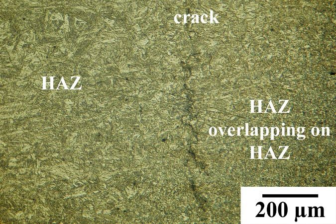
Appl. Sci. 2020, 10, x FOR PEER REVIEW 7 of 17
As previous investigations showed [44], used S355J2C+N steel is characterized by high7 of 16
Appl. Sci. 2020, 10, 1823
susceptibility to cold cracking. Those cracks can occur 72 h after welding. The NDT was prepared
after this time. During NDT some imperfections such as shape mistakes and spatters were found.
The results
The results of NDT
of NDT allowed
allowed us us
to to mark
mark areasfor
areas forDT
DTwithout
without surface
surfaceimperfections.
imperfections.TheThe
exemplary
exemplary
results of NDT are presented in
results of NDT are presented in Figure 3.Figure 3.
(a)
(b)
(c)
(d)
3. The
FigureFigure exemplary
3. The results
exemplary of of
results non-destructive
non-destructive testing (NDT):(a)(a)VTVT
testing (NDT): of of Specimen
Specimen 1; visual
1; (b) (b) visual
testing (VT) (VT)
testing of Specimen 3; (c)
of Specimen PTPT
3; (c) of of
Specimen
Specimen2;2;(d)
(d)penetrant testing(PT)
penetrant testing (PT)ofof Specimen
Specimen 5. 5.
3.2. Metallographic Macroscopic
3.2. Metallographic Testing
Macroscopic Testing
The macroscopic tests showed
The macroscopic the significant
tests showed differences
the significant in cross-sections
differences of prepared
in cross-sections specimens.
of prepared
Downloaded from mostwiedzy.pl
specimens.
Specimen Specimen
1 welded without1 welded without
additional additional
stitches stitches
(in-situ local (in-situ local heatwas
heat treatment) treatment)
brokenwasintobroken
two parts
into two parts through a fusion line (FL). It was proved that S355J2C+N steel is characterized
through a fusion line (FL). It was proved that S355J2C+N steel is characterized by high susceptibility by high
to cold cracking. In specimen 1 the gas pore in the weld was found (Figure 4a). Specimens in4a).
susceptibility to cold cracking. In specimen 1 the gas pore in the weld was found (Figure which
Specimens in which the additional stitches were laid were not broken into two parts. However, in
the additional stitches were laid were not broken into two parts. However, in Specimen 2, in which the
Specimen 2, in which the overlapping was 100%, the crack was found. This crack started near the
overlapping was 100%, the crack was found. This crack started near the notch and ran through the FL
notch and ran through the FL into weld. The length of this crack was 90% of the weld height (Figure
into weld.
4b). InThe length
other of thisnocrack
specimens was 90% were
imperfections of thefound.
weld The
height (Figure 4b).
exemplary, In other specimens
representative photos of no
imperfections were found. The exemplary, representative
macroscopic testing are presented in Figure 4. photos of macroscopic testing are presented
in Figure 4.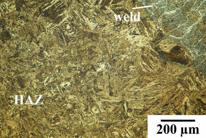
Appl. Sci. 2020, 10, 1823 8 of 16
Appl. Sci. 2020, 10, x FOR PEER REVIEW 8 of 17
(a)
(b)
(c)
Downloaded from mostwiedzy.pl
(d)
Figure 4. The exemplary results of macroscopic testing: (a) Specimen 1; (b) Specimen 2; (c) Specimen 5;
(d) Specimen
Figure 4.6.
The exemplary results of macroscopic testing: (a) Specimen 1; (b) Specimen 2; (c) Specimen
5; (d) Specimen 6.
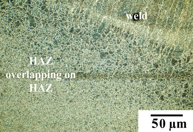
3.3. Metallographic Microscopic Testing
3.3. Metallographic Microscopic Testing
From each welded joint two specimens were observed using an optical microscope.
The observations were carried out in the weld, in BM and in HAZ. The microstructure of S355J2C+N
steel is characterized by the presence of fine-grained ferrite and fine-grained pearlite (Figure 5a).
The structure of the weld, which was not tempered by heat from additional stitch was the same in
each specimen. The dendritic structure was built of bright fine-grained ferrite arranged in columns,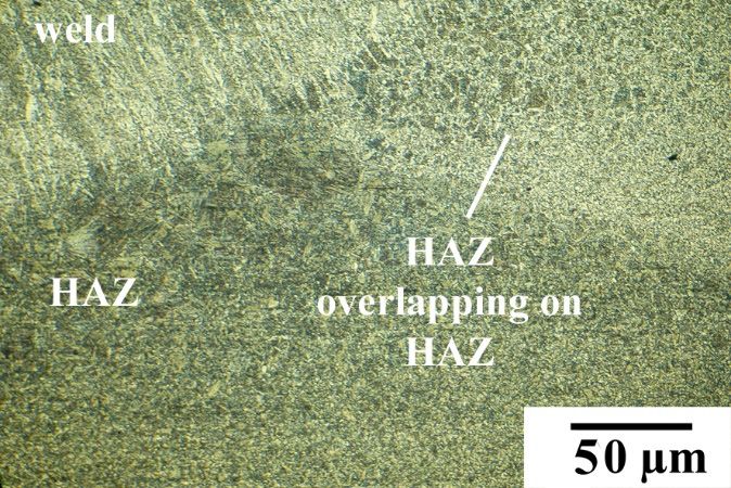
Appl. Sci. 2020, 10, 1823                                                                              9 of 16

                                from which grew acicular ferrite at the boundaries of dendrites. Inside dendrites were fine grains of
                                ferrite, which is typical for weld made under water (Figure 5b) [25,27,36]. The structures in HAZ were
                                different in each specimen. Specimen 1 welded without the additional stitches was characterized by
                                brittle, martensitic and bainitic structures (Figure 5b). The observed brittle structures are the result of a
                                high cooling rate generated by the water environment. Zhang et al. [40] stated that these structures
                                cause decreasing of the mechanical properties of underwater welded joints, and may increase the
                                susceptibility to cracking. The structures in HAZ in Specimen 2 were similar. The application of
                                additional stitch with the 100% overlapping did not affect changes of microstructures in the HAZ,
                                which generated cracks near the FL (Figure 5c). Similar results were found by Tasak et al. [51]. They
                                proved, that in some applications, the structure after heat treatment did not change, and still included
                                brittle martensite. Significant changes were observed in the weld of next specimens in areas where
                                the heat from the additional stitch was affected. These areas were characterized by disappearance of
                                the dendritic structure and the formation of a ferritic fine-grained structure (Figure 5d). The changes
                                in overlapping of tempering stitch contributes to tempering the brittle martensitic structure in the
                                HAZ. The structure in this area was mixed of brittle martensite, tempered martensite, ferrite and
                                pearlite (Figure 5e). The 80% overlapping provided a higher content of tempered structures in the
                                HAZ. However, cracks were still observed (Figure 5f). Using two tempering stitches with 100%
                                overlapping (Specimen 5) provided the best results. The in situ local heat treatment generated the
                                normalization structures with fine pearlite and fine ferrite in areas overlapping the HAZ from base
                                stitch and tempering stitches (Figure 5g). It was proved that the temper bead welding technique is
                                able to stop the cracking by the change of structure in bead-on plate welding conditions [52]. The
                                additional stitches were laid in the same direction as the Tekken test weld, within the maximum time
                                of two minutes after competition of previous welding process. It allows to increase the cooling rate
                                of prepared specimens. Sun et al. [53] performed an experiment with in situ quench and tempering
                                for microstructure control and enhanced the mechanical properties of a laser cladded process. They
                                proved that by pausing 80 s between tracks, a partial tempering effect was achieved. In this paper,
                                we achieved a similar tempering effect of the structures in HAZ. Jorge et al. [54] proved that longer
                                cooling times show a tendency to improvement of impact toughness of high-strength steel weld metals
                                obtained by GMAW process. It can be assumed that our technique would also improve the mechanical
                                properties. The microstructure in the area of overlapping of three HAZ in Specimen 5 was the same as
                                in Specimen 6 in the area where the third additional stitch with 10% overlapping generated in situ heat
                                treatment (Figure 5h). The structure in this area was built by normalized structures with fine pearlite
Downloaded from mostwiedzy.pl

                                and fine ferrite. The microstructure in HAZ (which did not overlap on the other HAZ) in the last stitch
                                is similar to the microstructure of the HAZ for Specimen 1 (without in situ local heat treatment). This
                                stitch provided the heat treatment of the previous laid stitches. In industrial applications, the last stitch
                                can be ground after completion of the welding process. Water as a welding environment causes a high
                                cooling rate of welded joints. The residual thermal stresses are generated as a result of the decreasing
                                of t8/5 time. Rahman Rashid et al. [55] proved that micro-cracking in the welds near the surface of the
                                clads is developed by high rates of surface solidification in air environment. The solidification rate of
                                the welds in the water is quicker, and caused the susceptibility to cracking in the weld. This may be
                                the reason for the cracks observed in the weld (Figure 5i) of Specimen 6. The exemplary results of
                                metallographic microscopic testing are presented in Figure 5.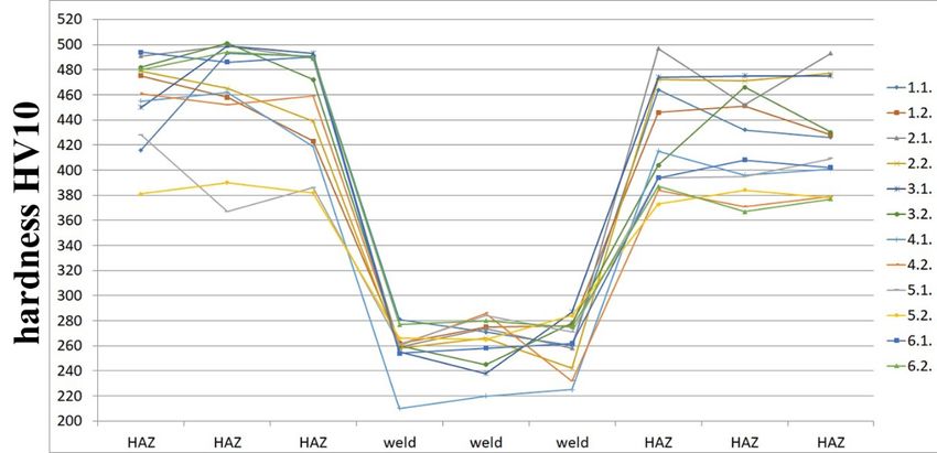
Appl. Sci. 2020, 10, 1823                                        10 of 16
                                Appl. Sci. 2020, 10, x FOR PEER REVIEW                           10 of 17

                                                                                           (a)

                                                                                           (b)

                                                                                           (c)
Downloaded from mostwiedzy.pl

                                                                                           (d)

                                                                         Figure 5. Cont.
Appl. Sci. 2020, 10, 1823 11 of 16
Appl. Sci. 2020, 10, x FOR PEER REVIEW 11 of 17
(e)
(f)
(g)
Downloaded from mostwiedzy.pl
(h)
Figure 5. Cont.Appl.
Appl.Sci. 2020,10,
Sci.2020, 10,1823
x FOR PEER REVIEW 12
12of
of16
17
(i)
Figure5.5. The
Figure The exemplary
exemplary results
results of
ofmicroscopic
microscopictesting:
testing: (a)
(a) S355J2C+N
S355J2C+N structure;
structure; (b)
(b) Specimen
Specimen 11
without
without in situ heat treatment—the view of the weld and heat-affected zone (HAZ); (c) Specimen 2,
in situ heat treatment—the view of the weld and heat-affected zone (HAZ); (c) Specimen 2,
one additional stitch with 100% overlapping—the view of the weld and HAZ; (d)
one additional stitch with 100% overlapping—the view of the weld and HAZ; (d) Specimen 3, one Specimen 3, one
additional
additionalstitch
stitchwith
with90%
90%overlapping—the
overlapping—the view of the
view tempered
of the tempered weld andand
weld HAZ; (e) Specimen
HAZ; 3, one3,
(e) Specimen
additional stitch with 90% overlapping—the view of the tempered HAZ; (f) Specimen
one additional stitch with 90% overlapping—the view of the tempered HAZ; (f) Specimen 4, one 4, one additional
stitch with 80% overlapping—the view of the weld and HAZ; (g) Specimen 5, two additional stitches
additional stitch with 80% overlapping—the view of the weld and HAZ; (g) Specimen 5, two
with 100% overlapping—the view of the tempered HAZ; (h) Specimen 6, three additional stitches with
additional stitches with 100% overlapping—the view of the tempered HAZ; (h) Specimen 6, three
10% overlapping of the las—the view of the tempered HAZ t; (i) Specimen 6, three additional stitches
additional stitches with 10% overlapping of the las—the view of the tempered HAZ t; (i) Specimen 6,
with 10% overlapping of the last stitch—the view of the weld.
three additional stitches with 10% overlapping of the last stitch—the view of the weld.
3.4. Hardness HV10 Measurements
3.4. Hardness HV10 Measurements
For hardness HV10 measurements, the Sinowon V-10 stand (Sinowon, Dongguan, China) was
used. For
Thehardness
hardnessHV10 measurements,
was measured in threethe Sinowon
points in theV-10
weldstand
and in(Sinowon,
six pointsDongguan,
in the HAZ—threeChina) was in
used. The hardness was measured in three points in the weld and in six
the left side from the axis of tested specimen and three in right side. Measurements were undertaken points in the HAZ—three in
the left side from the axis of tested specimen and three in right side. Measurements
in two cross-sections of each specimen (e.g., 1.1. and 1.2. for Specimen 1). Rahman Rashid et al. [56] were undertaken
in two cross-sections
proved that decreasing of hardness
each specimen (e.g.,from
can result 1.1. and 1.2. for martensite
tempered Specimen 1). RahmaninRashid
occurring the HAZ.et al.The
[56]
proved
same that were
results decreasing
observed hardness
duringcanourresult from tempered
investigation. Hardness martensite occurring in confirmed
HV10 measurements the HAZ. the The
same results were observed during our investigation. Hardness HV10
microscopic observations. The highest HV10 values were measured in the HAZ, whose structures measurements confirmed the
microscopic observations. The highest HV10 values were measured in the
were identified as brittle bainitic and martensitic structure. Lisiecki and Ślizak [57] stated, that high HAZ, whose structures
were identified
hardness of welded as brittle
layersbainitic
was causedand bymartensitic structure.
a high cooling Lisieckiwelding
rate during and Ślizak [57] stated,
process. that high
The significant
hardness of welded layers was caused by a high cooling rate during welding
effect of in situ local heat treatment was observed for Specimen 5, modified by two additional stitches. process. The significant
Downloaded from mostwiedzy.pl
effect
The of in situ
hardness HV10 local heatin treatment
values this Specimenwasinobserved
HAZ were forlower
Specimen
by 70–90 5, modified
compared by twoSpecimen
to the additional 1,
stitches. The hardness HV10 values in this Specimen in HAZ were
which was performed without additional stitches. The proposed technique caused decreasing of lower by 70–90 compared tothe
the
Specimenin 1,
hardness HAZwhich was sides
on both performed
of weldwithout additional5,stitches.
axis. In Specimen the biggestThetempering
proposedeffect technique caused
was observed
decreasing
during of the hardness
microscopic testing. Forin HAZ on both
Specimens sides
4 and of weld
6, where anaxis. In Specimen
additional stich was5, the
nonbiggest tempering
symmetrical, the
effect was observed during microscopic testing. For Specimens 4 and
hardness decreased in heat treatment areas (HAZ on right side from weld axis). The aim of using such 6, where an additional stich
awas
lownonvalue symmetrical,
of overlapping the like
hardness decreased
in Specimen in heat
6 (10%) wastreatment
temperingareas (HAZ
the area onthe
near rightedgesidetofrom
checkweld
the
axis). Theofaim
influence thisofvalue
usingon such
the aweldability
low value of of overlapping
HSLA steel. like The in Specimen
prepared 6 (10%) wasconfirmed
examinations temperingthat the
area near the edge to check the influence of this value on the weldability
10% overlapping caused microstructural changes and a decrease of hardness in the HAZ of Tekken test of HSLA steel. The
prepared
weld. examinations
It proved confirmed
that the applied methodthatof10% overlapping
in situ caused microstructural
local heat treatment can be used during changes and a
underwater
decrease of hardness in the HAZ of Tekken test weld. It proved that
welding as a technique, which improved the weldability of the HSLA steel in wet welding conditions. the applied method of in situ
local heat treatment can be used during underwater welding as a technique,
However, it was observed that overlapping higher than 80% of one stitch generated higher hardness which improved the
weldability
and should be of the HSLAThe
avoided. steelresults
in wetof welding conditions.
HV10 hardness However, it was
measurements are observed
presentedthat overlapping
in Table 4. The
higher than 80% of one stitch generated higher
hardness distribution in each specimens is presented in Figure 6. hardness and should be avoided. The results of HV10
hardness measurements are presented in Table 4. The hardness distribution in each specimens is
presented in Figure 6.
Table 4. The results of HV10 hardness measurements.
Specimen No. Heat Affected Zone (HAZ) Base Material (BM) HAZ
1.1. 416 493 491 281 271 260 464 432 426
1.2. 475 458 423 262 275 276 446 451 428Appl. Sci. 2020, 10, 1823 13 of 16
Table 4. The results of HV10 hardness measurements.
Appl. Sci. 2020, 10, x FOR
Specimen No. PEER REVIEW
Heat Affected Zone (HAZ) Base Material (BM) HAZ 13 of 17
1.1. 416 493 491 281 271 260 464 432 426
1.2. 2.1. 475 491
458 499
423 489
262 259275 274 276258 497
446 452 451493 428
2.1. 2.2. 491 499
479 489
465 259
439 258274 266 258242 497
472 471 452477 493
2.2. 3.1. 479 465
450 439
499 258
493 255266 238 242287 472
474 475 471475 477
3.1. 450 499 493 255 238 287 474 475 475
3.2.
3.2. 482
482
501
501
472
472
260
260245 245 278
278 404
404
466 466430 430
4.1. 4.1. 455 455
462 462
419 419
210 210220 220 225225 415
415 396 396401 401
4.2. 4.2. 461 461
452 452
459 459
260 260286 286 232232 384
384 371 371379 379
5.1. 5.1. 428 367
428 386
367 261
386 261284 284 271271 394
394 398 398409 409
5.2. 5.2. 381 390
381 382
390 266
382 266265 265 284284 373
373 384 384378 378
6.1. 494 486 490 254 258 262 394 408 402
6.2.
6.1. 480
494
494
486
490
490
277
254280 258 275
262 394
387
408 367402 377
6.2. 480 494 490 277 280 275 387 367 377
Figure
Figure 6.
6. The
The distribution
distribution of
of hardness
hardness HV10
HV10 measurements
measurements for all specimens.
The effect of decreasing of HV10 hardness due to in situ local heat treatment can be observed in
areas where
where heat
heatfrom
fromadditional
additionalstitch
stitchtempered
tempered thethemicrostructures
microstructures of the basebase
of the Tekken test test
Tekken joint.joint.
The
measurements
The measurements showed showedthat that
therethere
are significant differences
are significant in HAZ
differences on both
in HAZ sidessides
on both of theofTekken
the Tekken joint.
TheseThese
joint. differences resulted
differences from different
resulted heat influence
from different on the joint.
heat influence In the
on the HAZ
joint. In near the additional
the HAZ near the
Downloaded from mostwiedzy.pl
stitch (Specimens
additional 4 and 6) the 4heat
stitch (Specimens andprovides
6) the heatmicrostructural changes, whichchanges,
provides microstructural produced lowerproduced
which hardness.
The HAZ
lower on other
hardness. The side
HAZfrom onthe weld
other axis
side havethe
from notweld
beenaxis
tempered
have not as much and the hardness
been tempered as muchisand similar
the
to the hardness
hardness in Specimen
is similar 1 welded without
to the hardness in situ1heat
in Specimen treatment.
welded withoutAlipooramirabad et al. [58]
in situ heat treatment.
proved that hardness
Alipooramirabad level
et al. in the
[58] welded
proved thatjoint can be related
hardness level intothe
the welded
microstructure
joint canconstituent
be related of bainite
to the
and Widmanstäten
microstructure ferrite. These
constituent type of
of bainite andstructures were observed
Widmanstäten ferrite.during
These ourtype microscopic
of structures testing
werein
specimens, which are characterized by the highest HV10 hardness values.
observed during our microscopic testing in specimens, which are characterized by the highest HV10 For Specimen 5, in which
the additional
hardness stitch
values. Forwas produced
Specimen by which
5, in bead-on plate
the conditions
additional with
stitch wastheproduced
100% overlapping,
by bead-on theplate
heat
was implemented
conditions with the symmetrically,
100% overlapping, which theprovided a decrease
heat was of the hardness
implemented values which
symmetrically, in the whole
provided HAZ, a
which resulted
decrease of the from tempering
hardness the microstructure
values in the whole in this
HAZ,region.
which resulted from tempering the
microstructure in this region.
4. Conclusions
4. Conclusions
In the paper the effect of in situ local heat treatment on the weldability of HSLA steel welded
under Inwater in wetthe
the paper welding
effect conditions was studied.
of in situ local The investigations
heat treatment showed of
on the weldability that additional
HSLA stitches
steel welded
can improve the quality of welded joints in the water environment. The additional
under water in wet welding conditions was studied. The investigations showed that additional stitches provided
microstructural
stitches changes
can improve in the HAZ,
the quality decreasing
of welded joints the hardness
in the in this area. Prepared
water environment. investigations
The additional stitches
showed that
provided the optimal number
microstructural of stitches
changes in the with
HAZ, 100% overlapping
decreasing the for S355J2C+N
hardness steelarea.
in this welded in wet
Prepared
welding conditions is three.
investigations showed that the optimal number of stitches with 100% overlapping for S355J2C+N
steel The main
welded inconclusions
wet weldingresulting from
conditions is experiments
three. are:
The main conclusions resulting from experiments are:
1. The investigated S355J2C+N steel is characterized by poor weldability in wet welding
conditions. The way to improve the weldability in the water environment is in situ local heatAppl. Sci. 2020, 10, 1823 14 of 16
1. The investigated S355J2C+N steel is characterized by poor weldability in wet welding conditions.
The way to improve the weldability in the water environment is in situ local heat treatment
provided by additional welded stitches. During non-destructive testing it was observed that
these stitches do not cause imperfections on the surface.
2. The additional stitch laid on the face of welded joint contributed to tempering of brittle structures
in heat-affected zones which generated lower values of HV10 hardness. The tempered martensite
and normalized structures were observed during microscopic testing.
3. For improvement of the weldability of S355J2C+N steel in a water environment, two additional
stitches with 100% overlapping should be laid. This technique generated normalized structures
with fine pearlite and fine ferrite in the HAZ, which decrease hardness in this area by 70–90 HV10.
The higher number of additional stitches provided microstructure changes in the welded joint,
which may result from increasing the crucial t8/5 time.
4. The positive effect can also be achieved by bead-on plate welding with the one stitch with
overlapping lower then 80%. Welding with higher values increased the hardness and did not
affect the tempering of HAZ.
Author Contributions: Conceptualization, J.T.; methodology, J.T.; validation, J.T.; formal analysis, J.T.;
investigation, J.T. and A.J.; writing—original draft preparation, J.T.; writing—review and editing, J.T. and
A.J.; supervision, J.T.; All authors have read and agreed to the published version of the manuscript.
Funding: This research received no external funding.
Acknowledgments: Authors want to thank Dariusz Fydrych from Gdańsk University of Technology for the
support and his guidance during our work.
Conflicts of Interest: The authors declare no conflict of interest.
References
1. Aleksić, V.; Milović, L.; Blacić, I.; Vuherer, T.; Bulatović, S. Effect of LCF on behavior and microstructure of
microalloyed HSLA steel and its simulated CGHAZ. Eng. Fail. Anal. 2019, 104, 1094–1106. [CrossRef]
2. Den Besten, H. Fatigue criteria classification, modeling, developments and trends for welded joints in marine
structures. Ships Offshore Struct. 2018, 13, 787–808. [CrossRef]
3. Hu, J. Application of long-distance microscope in crack detection in bridge construction. Acta Microsc. 2019,
28, 1151–1158.
4. Park, J.H.; Moon, H.S. Advanced automatic welding system for offshore pipeline system with seam tracking
Downloaded from mostwiedzy.pl
function. Appl. Sci. 2020, 10, 324. [CrossRef]
5. Bunaziv, I.; Olden, V.; Akselsen, O.M. Metallurgical aspects in the welding of clad pipelines–A global outlook.
Appl. Sci. 2019, 9, 3118. [CrossRef]
6. Dirisu, P.; Ganguly, S.; Mehmanparast, A.; Martina, F.; Williams, S. Analysis of fracture toughness properties
of wire + arc additive manufactured high strength low alloy structural steel components. Mater. Sci. Eng. A
2019, 765, 138285. [CrossRef]
7. Zhu, L.; Wang, Y.; Wang, S.; Zhang, Q.; Zhang, C. Research of microalloy elements to induce intragranular
acicular ferrite in shipbuilding steel. Ironmak. Steelmak. 2019, 46, 499–507. [CrossRef]
8. Law, D.W.; Nicholls, P.; Christodoulou, C. Residual protection of steel following suspension om Impressed
Current Cathodic Protection system on a wharf structure. Constr. Build. Mater. 2019, 210, 48–55. [CrossRef]
9. Dehghani, A.; Aslani, F. A review on defects in steel offshore structures and developed strengthening
techniques. Structures 2019, 20, 635–657. [CrossRef]
10. Chmielewski, T.; Hudycz, M.; Krajewski, A.; Sałaciński, T.; Skowrońska, B.; Świercz, R. Structure investigation
of titanium metallization coating deposited onto AlN ceramics substrate by means of friction surfacing
process. Coatings 2019, 9, 845. [CrossRef]
11. Adamiak, M.; Czupryński, A.; Kopyść, A.; Monica, Z.; Olender, M.; Gwiazda, A. The properties of arc-sprayed
aluminum coatings on armor-grade steel. Metals 2018, 8, 142. [CrossRef]
12. Sałaciński, T.; Chmielewski, T.; Winiarski, M.; Cacko, R.; Świercz, R. Roughness of metal surface after
finishing using ceramic brush tools. Adv. Mater. Sci. 2018, 18, 20–27. [CrossRef]Appl. Sci. 2020, 10, 1823 15 of 16
13. Li, C.; Dong, S.; Wang, T.; Xu, W.; Zhou, X. Numerical investigation on ultimate compressive strength of
welded stiffened plates built by steel grades of S235-S390. Appl. Sci. 2019, 9, 2088. [CrossRef]
14. Kik, T.; Moravec, J.; Nováková, I. Numerical simulations of X22CrMoV12-1 steel multilayer welding.
Arch. Metall. Mater. 2019, 64, 1441–1448. [CrossRef]
15. Winczek, J. Modeling of temperature field during multi-pass GMAW surfacing or rebuilding of steel elements
taking into account the heat of the deposit metal. Appl. Sci. 2016, 7, 6. [CrossRef]
16. Sajek, A.; Nowacki, J. Comparative evaluation of various experimental and numerical simulation methods
for determination of t(8/5) cooling times in HPAW process weldments. Arch. Civ. Mech. Eng. 2018, 18,
583–591. [CrossRef]
17. Fu, H.; Xu, B.; Xiao, Q.; Li, S.; Zhang, X.; Bian, S.; Kang, T. Effect of preheating temperature on post-weld
residual stress of dissimilar steel plates. Metalurgija 2020, 59, 150–152. Available online: https://hrcak.srce.hr/
232360 (accessed on 6 March 2020).
18. Landowski, M. Influence of parameters of laser beam welding on structure of 2205 duplex stainless steel.
Adv. Mater. Sci. 2019, 19, 21–31. [CrossRef]
19. Świerczyńska, A. Effect of storage conditions of rutile flux cored welding wires on properties of welds.
Adv. Mater. Sci. 2019, 19, 46–56. [CrossRef]
20. Hu, Y.; Shi, Y.; Sun, K.; Shen, X. Effect of filler Si content on the microstructure and properties of underwater
hyperbaric welded duplex stainless steel. J. Mater. Process. Technol. 2020, 279, 116548. [CrossRef]
21. Hu, Y.; Shi, Y.; Shen, X.; Wang, Z. Microstructure evolution and selective corrosion resistance in underwater
multi-pass 2101 duplex stainless steel welding joints. Metall. Mater. Trans. A 2018, 49, 3306–3320. [CrossRef]
22. Guo, N.; Fu, Y.; Xing, X.; Liu, Y.; Zhao, S.; Feng, J. Underwater local dry cavity laser welding of 304 stainless
steel. J. Mater. Process. Technol. 2018, 260, 146–155. [CrossRef]
23. Rogalski, G.; Fydrych, D.; Łabanowski, J. Underwater wet repair welding of API 5L X65M pipeline steel. Pol.
Marit. Res. 2017, 24, 188–194. [CrossRef]
24. Yang, Q.; Han, Y.; Chen, J.; Dong, S.; Wu, C.; Jia, C. Visual investigation on the arc burning behaviors and
features in underwater wet FCAW. J. Offshore Mech. Arct. Eng. 2020, 1–22. [CrossRef]
25. Tomków, J.; Fydrych, D.; Rogalski, G.; Łabanowski, J. Temper bead welding of S460N steel in wet welding
conditions. Adv. Mater. Sci. 2018, 18, 5–14. [CrossRef]
26. Tomków, J.; Czupryński, A.; Fydrych, D. The abrasive wear resistance of coatings manufactured on
high-strength low-alloy (HSLA) offshore steel in wet welding conditions. Coatings 2020, 10, 219. [CrossRef]
27. Tomków, J.; Fydrych, D.; Rogalski, G.; Łabanowski, J. Effect of the welding environment and storage time of
electrodes on the diffusible hydrogen content in deposited metal. Rev. Metal. 2019, 55, e140. [CrossRef]
28. Wasim, M.; Djukic, M.B. Hydrogen embrittlement of low carbon structural steel at macro-, micro-, and
Downloaded from mostwiedzy.pl
nano-levels. Int. J. Hydrog. Energy 2020, 45, 2145–2156. [CrossRef]
29. Rhode, M.; Richter, T.; Mayr, M.; Nitsche, A.; Mente, T.; Böllinghaus, T. Hydrogen diffusion in creep-resistance
9% Cr P91-multi-layer weld metal. Weld. World 2020, 64, 267–281. [CrossRef]
30. Świerczyńska, A.; Fydrych, D.; Landowski, M.; Rogalski, G.; Łabanowski, J. Hydrogen embrittlement of
X2CrNiMoCuN25-6-3 super duplex stainless steel welded joints under cathodic protection. Constr. Build. Mater.
2019, 238, 117697. [CrossRef]
31. Wu, W.; Wang, Y.; Tao, P.; Li, X.; Gong, J. Cohesive zone modeling of hydrogen-inducted delayed intergranular
fracture in high strength steels. Results Phys. 2018, 11, 591–598. [CrossRef]
32. Wang, J.; Sun, Q.; Zhang, T.; Tao, X.; Jin, P.; Feng, J. Arc stability indexes evaluation of ultrasonic wave-assisted
underwater FCAW using electrical signal analysis. Int. J. Adv. Manuf. Technol. 2019, 103, 5–8. [CrossRef]
33. Xu, C.; Guo, N.; Zhang, X.; Chen, H.; Fu, Y.; Zhou, L. Internal characteristic of droplet and its influence on
the underwater wet welding process stability. J. Mater. Process. Technol. 2020, 280, 116593. [CrossRef]
34. Chen, H.; Guo, N.; Xu, K.; Xu, C.; Zhou, L.; Wang, G. In-situ observations of melt degassing and hydrogen
removal enhanced by ultrasonics in underwater wet welding. Mater. Des. 2020, 188, 108482. [CrossRef]
35. Fydrych, D.; Łabanowski, J.; Tomków, J.; Rogalski, G. Cold cracking of underwater wet welded S355G10+N
high strength steel. Adv. Mater. Sci. 2015, 15, 48–56. [CrossRef]
36. Tomków, J.; Fydrych, D.; Rogalski, G. Role of bead sequence in underwater welding. Materials 2019, 12, 3372.
[CrossRef] [PubMed]
37. Han, Y.; Dong, S.; Zhang, M.; Jia, C.; Zhang, M.; Wu, C. A novel underwater submerged-arc welding acquires
sound quality joints for high strength marine steel. Mater. Lett. 2020, 261, 127075. [CrossRef]Appl. Sci. 2020, 10, 1823 16 of 16
38. Wang, J.; Sun, Q.; Zhang, T.; Xu, P.; Feng, J. Experimental study of arc bubble growth and detachment from
underwater wet FCAW. Weld. World 2019, 63, 1147–1759. [CrossRef]
39. Menezes, P.; Pessoa, E.; Bracarense, A.Q. Comparison of underwater wet welding performed with silicate
and polymer agglomerated electrodes. J. Mater. Process. Technol. 2019, 266, 63–72. [CrossRef]
40. Zhang, T.; Dai, X.; Feng, J.; Hu, L. Preliminary investigation on real-time induction heating-assisted
underwater wet welding. Weld. J. 2015, 94, 8–15.
41. Rathod, D.W.; Sun, Y.; Obasi, G.C.; Roy, M.J. Effect of multiple passes on Lüders/yield plateaus, microstructure
and tensile behavior of narrow-gap thick-section weld plates. J. Mater. Sci. 2019, 54, 12833–12850. [CrossRef]
42. Górka, J. Assessment of the weldability of T-welded joints in 10 mm thick TMCP steel using laser beam.
Materials 2018, 11, 1192. [CrossRef] [PubMed]
43. Skowrońska, B.; Chmielewski, T.; Golański, D.; Szulc, J. Weldability of S700MC steel welded with the hybrid
plasma + MAG method. Manuf. Rev. 2020, 7, 4. [CrossRef]
44. Tomków, J.; Janeczek, A. The influence of the welding environment on the properties of Tekken joints made
from S355J2C+N steel. Weld. Technol. Rev. 2019, 91, 8–12. [CrossRef]
45. A Classification of Coated Rod Electrodes for Arc Welding of Unalloyed Steel and Fine-Grained Steel; ISO 2560;
ISO: Geneva, Switzerland, 1908.
46. Destructive Tests on Welds in Metallic Materials—Cold Cracking Tests for Weldments—Arc Welding Processes;
EN ISO 17642; ISO: Geneva, Switzerland, 2015.
47. Non-Destructive Testing of Welds—Visual Testing of Fusion-Welded Joints; EN ISO 17637; ISO: Geneva, Switzerland,
2017.
48. Non-Destructive Testing—Penetrant Testing—Part 1: General Principles; EN ISO 3452-1; ISO: Geneva, Switzerland,
2013.
49. Destructive Tests on Welds in Metallic Materials. Macroscopic and Microscopic Examination of Welds; EN ISO
17639; ISO: Geneva, Switzerland, 2013.
50. Destructive Tests on Welds in Metallic Materials. Hardness Testing. Hardness Test on Arc Welded Joint; EN ISO
9015-1; ISO: Geneva, Switzerland, 2011.
51. Tasak, E.; Ziewiec, A.; Zielińska-Lipiec, A.; Ziewiec, K. Problems of pad welding structural steels with
martensitic filler material. Adv. Mater. Sci. 2019, 19, 5–14. [CrossRef]
52. Tomków, J.; Rogalski, G.; Fydrych, D.; Łabanowski, J. Improvement of S355G10+N steel weldability in water
environment by temper bead welding. J. Mater. Process. Technol. 2018, 262, 372–381. [CrossRef]
53. Sun, S.D.; Fabijanic, D.; Barr, C.; Liu, Q.; Walker, K.; Matthews, N.; Orchowski, N.; Easton, M.; Brandt, M.
In-situ quench and tempering for microstructure control and enhanced mechanical properties of laser cladded
AISI 420 stainless steel powder on 300M steel substrates. Surf. Coat. Technol. 2018, 333, 210–219. [CrossRef]
Downloaded from mostwiedzy.pl
54. Jorge, J.C.F.; Monteiro, J.L.D.; de Carvalho Gomes, A.J.; de Souza Bott, I.; de Souza, L.F.G.; Mendes, M.C.;
Araújo, L.S. Influence of welding procedure and PWHT on HSLA steel weld metals. J. Mater. Res. Technol.
2018, 8, 561–571. [CrossRef]
55. Rahman Rashid, R.A.; Abaspour, S.; Palanisamy, S.; Matthews, N.; Dargusch, M.S. Metallurgical
and geometrical characterisation of the 316L stainless steel clad deposited on a mild steel substrate.
Surf. Coat. Technol. 2017, 327, 174–184. [CrossRef]
56. Rahman Rashid, R.A.; Nazari, K.A.; Barr, C.; Palanisamy, S.; Orchowski, N.; Matthews, N.; Dargusch, M.S.
Effect of laser reheat post-treatment on the microstructural characteristics of laser-cladded ultra-high strength
steel. Surf. Coat. Technol. 2019, 372, 93–102. [CrossRef]
57. Lisiecki, A.; Ślizak, D. Hybrid laser deposition of Fe-based metallic powder under cryogenic conditions.
Metals 2020, 10, 190. [CrossRef]
58. Alipooramirabad, H.; Paradowska, A.; Ghomashchi, R.; Reid, M. Investigating the effects of welding process
on residual stresses, microstructure and mechanical properties in HSLA steel welds. J. Manuf. Process. 2017,
28, 70–81. [CrossRef]
© 2020 by the authors. Licensee MDPI, Basel, Switzerland. This article is an open access
article distributed under the terms and conditions of the Creative Commons Attribution
(CC BY) license (http://creativecommons.org/licenses/by/4.0/).You can also read