Using sketch recognition for capturing developer's mental models
←
→
Page content transcription
If your browser does not render page correctly, please read the page content below
Using sketch recognition for capturing developer’s
                   mental models
                                   Tatiana De-Wyse, Emmanuel Renaux, José Mennesson
                                          IMT Lille Douai/CRIStAL (UMR CNRS 9189)
                                                    University of Lille, France
                                              firstname.lastname@imt-lille-douai.fr

   Abstract—The purpose of agile practices is to optimize engi-       stories, programs, tests cases, and other deliverables created
neering processes. Beside it, software documentation often suffers    before designing and implementing the system.
from the priority given to fast and successive deliveries of new         Among these artifacts, graphical representations are widely
functionalities. As a consequence, incomplete documentation and
graphical representation make it difficult for a developer to         used to model the system, as in Industrial Software Devel-
maintain and evolve. Sketching is an integral part of the software    opment [40]. UML1 [31] is a standard modeling language
design and development. Indeed, among other stakeholders,             and a graphical representation that fosters communication
developers use sketches to informally share knowledge about           and visualization of software architecture. As a graphical
source code. Since sketches are often hand-drawn, written on          representation of the system, it helps to understand, discuss or
paper or whiteboard without any additional technology tool, they
are not considered as an artifact in agile method or traditional      brainstorm about it. The strength of UML is that any developer
engineering process but as a disposable production.                   understands it since he learned it at school and it is the de facto
   In this work, we focus on sketches containing Unified Modeling     standard for modeling and designing information system.
Language (UML) diagrams. To produce documentation or to                  However, UML is often subject to negative press and is
exploit information from this kind of sketches, developers have to    considered as a waste of time. But surveys like [6], [29]
transcribe it in a UML case tool, what they see as a waste of time
that hinders productivity. We argue that sketches might be worth
                                                                      highlight that although many engineers say they do not use
considering as non-code artifacts. The fact is that developer or      UML, they use it informally. In fact, engineers actually admit
designer drop informally a lot of information about the software,     doing sketches of UML diagrams [2], [28] during activities
which is unusable.                                                    like:
   Our goal is to verify that simply capturing sketches can provide
                                                                         • Sharing knowledge about the code in collocated design
useful information for later use and then improve the modeling
process efficiency. In this paper, we present a preliminary                 collaborations [10]
approach that consists in automatically capture information from         • Exchanging ideas in design software session with easy
the sketches using image processing and pattern recognition. We             transitions between different types of sketches like lists,
propose a fledgling prototype that demonstrates the proposal’s              tables, GUIs, ER diagrams, class diagrams, code, draw-
viability. Then, as a future work, we plan to put in the hands
                                                                            ings. Sketches support mental simulations, reviews of
of the developers a finalized version of our prototype and study
the added value of our proposal.                                            designers progress and discussions of alternative [28]
   Index Terms—Sketch, UML, Image recognition, Engineering               • Creating informal graphical representations to quickly
Process, empirical study                                                    document workflows. Sketches help the comprehension
                                                                            of code [2]
                       I. I NTRODUCTION                                  • Supporting their development workflows by helping them
                                                                            for different purpose and context [43]
   More and more developers are adopting agile practices, no             • Finally, externalizing their mental models of source code.
matter if it is a fad or a pragmatic evolution of methodologies.            Tools do not allow to support face-to-face communication
In agile approaches, the source code is considered as the                   [9]
most valuable artifact. It leaves aside other means to de-               In the next section, we highlight some obstacles to the
scribe the architecture or functionalities like models and other      adoption of UML in traditional engineering practices. Since
human-readable documents. Nevertheless, developers create             there is little documentation of the software architecture, in
and maintain non-code artifacts [14] when developing and              section III, we justify the use of sketches to capture develop-
evolving software. These non-code artifacts help to express           ers’ mental models of their source code. Related work focuses
the requirements, understand the software architecture or doc-        on sketching tools in section IV. In section V, we introduce
ument the source code. Each one is dedicated to specific              our prototype that captures and understand sketches without
stakeholders and allows to communicate, exchange and main-            any effort from the developers. In the prototype, we firstly
tain the system. The Unified Process [22] precisely defined           restricted our focus to the UML class diagram. Finally, we
different types of artifacts throughout the project lifecycle, in     discuss a survey we need to further validate our work and the
order to ensure high-quality software production. The agile
methodScrum [33], implies more roughly documents like user              1 Unified   Modeling Language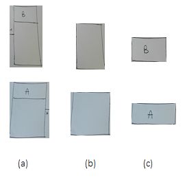
next steps that have to be created to prove that capitalizing on   Point & Click diagramming tool suffers from the lack of
sketches can improve the development process efficiency.           collaborative capacities. In collaborative activities, co-workers
                                                                   need awareness about artifacts and other coworkers. They need
        II. W EAK ADOPTION OF UML IN IT PROJECTS
                                                                   information about who, how and why things have been done
   Documentation and modeling tasks require significant time       and then they have to exchange with other co-workers [21].
to be produced and maintained. IT project engineers do not         The use of these point & click solutions could be reduced
maintain quality models since they see them as a waste             by trying to retrieve both the information contained in the
of time and effort. Although this proposal is controversial        sketches and other contextual information.
[29], [40], developers prefer to use this time and effort in
implementing new functionalities, passing tests and solving        C. Cognitive shift due to the proliferation of tools
problems. Moreover, agile practices do not help the adoption
of UML as they speed up the pace of deliveries. To counter            The need for knowledge exchange and code explanation
these adverse developments, we selected in the literature,         fosters the use of communication and social tools [39].
three obstacles to the adoption of UML or other graphical          This increases even more, the number of tools used by
representations in IT projects. Sketching is the more natural      developers. Switching from one tool to another or interruption
way to draw UML models, even if they are not as formal as in       due to instant messaging, for instance, cause cognitive
a UML tool. We think and want to verify that more sketches         shift and knowledge loss. This reduces the efficiency of
in projects and a simply manner to exploit them can help to        the development process and increases the feeling of a
counter these obstacles, and reintroduce software architecture     waste of time. Surveys like [14] show that existing tools do
modeling as an efficient practice.                                 not provide sufficient support for carrying out some tasks
                                                                   like visualizing artifacts that are larger than their screen
A. Operational software rather than comprehensive documen-         and with interconnected artifacts that have to be accessed
tation                                                             simultaneously. The methods to deal with that problem are
   Agile practices encourage short development cycles to pro-      inefficient and frequently error-prone. By reducing the number
duce a shippable product increment. In these methods highly        of tools and exploiting the engineer’s workstation equipped
used nowadays, documentation and models are seen as a              with a keyboard and draft paper containing his sketches, we
burden artifact [38]. Hence, the code and testing have taken       wish to limit the cognitive shift.
the leadership over exhaustive documentation and graphical
design of the software architecture. In terms of tools, teams        Let’s see in the following how we plan to counter these
mainly use development tools and project management tools          obstacles through a better consideration of sketches.
like Jira2 . In a simplistic view, the only non-code artifacts
are the user stories. They make it possible to organize sprints      III. C APTURING MENTAL MODEL THROUGH SKETCHES
and collaboratively monitor the project on a Kanban board.                                 RECOGNITION
Globally, agile processes leave little room for modeling tools        In traditional development processes, lack of documentation
and models. Quick brainstorming sketches contain information       is a factor of loss in efficiency. For the reasons we gave
about the source code architecture. It would be nice to be able    previously, developers do not produce an exhaustive UML
to easily retrieve some of this information.                       model of their source code. However, they create and maintain
B. Inadequacy of Point&Click tools                                 mental models of the architecture of the code. Inevitably
   Even if project management tools are used, in [1] Azizyan et    there is a loss of code knowledge and developers spend time
al. show that collocated teams prefer physical walls and paper.    understanding and trying to recover the rationale behind the
Developers also not use Point and Click solutions to model or      code. They rely on and interrupt their co-workers to find
maintain software architecture and its behavior but prefer to      answer when they get stuck by a task [24]. The consequence is
use paper or whiteboard. They find them more flexible [34]         that the code becomes hard to debug and complex to maintain
as paper and whiteboard allow developers to use their own          [12].
graphical representation (informal notation). They used the           Understanding the rationale behind source code is the
sketch as memory help for debugging, explaining task and           biggest problem for developers. Graphical representations help
refine or improve their idea [43]. Then, if it is required it      to understand, to discuss, to brainstorm, etc. Sketches are an
allows the preparation of formal documentation and developers      example of informal visualizations that are often created when
transcribe sketches in a formal way [2]. Sometimes, to deal        understanding or explaining the source code [2]. Moreover,
with the lack of documentation of the source code, software        hand-drawn is a natural and flexible way to model a domain.
visualization tools and reverse engineering tools automatically    And even if the sketch do not respect formal notation of
provide the UML representation of code for better under-           modeling language they foster later their creation. Contrary
standing and localization of code source. For example, this        to the point & click solution that requires the respect of their
helps developers to take in hand unfamiliar code [25]. Finally,    notation, hand-drawn do not constraint developers. Surveys
                                                                   have revealed that developers make sketches, which often
  2 https://fr.atlassian.com/software/jira                         contain UML diagrams [2], [40].
We base our work on the fact that sketches and diagrams sketches are lost, and also a lot of information expressed
give an accurate picture of parts of the developers’ mental informally.
model and help to understand a software project [24]. But b) Informal early design: Informal sketching tool fosters
since the sketch life cycle is short [43], our goal is to the communication and collaboration between different stake-
design a tool that could help us to analyze transparently the holders.
sketches and to exploit the information contained. We want Calico [27] is a system for e-whiteboard which proposes
to improve the software development process using graphical a canvas for managing and drawing a digital sketch. No
representation more efficiently with a minimum of effort and recognition of what is drawn is provided and links between
without disturbing the development activity. The key success sketches have to be done manually by the user.
factor is for us: capturing the mental model of the developers Gambit [32] supports collaborative early design session of user
in their sketches through sketch recognition. interface (UI). Designed according to a client-server model, it
can store and retrieve digital hand-drawn sketches. Users of
IV. R ELATED W ORK Gambit can annotate and use it on a tablet, desktop, and video-
There are a lot of sketching tools since the different devices projector.
allowing sketching activity are numerous. In software design AugIr [20] provides an interaction room system by combining
and development practices, only a few of them allow the multiple e-whiteboards. Stakeholders can manipulate hierar-
recognition of sketch elements and their semantic meaning chical canvas and freely organize their views. Size, direction
as shown in table I. Here is a list of available sketching tools and temporal context of drawn stroke are analyzed to recognize
we found in a comprehensive survey of the literature. meaningful text and match the artifact with link automatically.
IdeaVis [13] is a tool for co-located sketching sessions. It uses
A. Tools allowing digital sketching activity
digital paper and pen for sketch creation and manipulation on
Digital Sketching defines a sketching activity realized large interactive display for presentation.
thanks to an electronic device like digital pen or finger on FlexiSketch [44] and his extension FlexiSketch Team [45],
a touch screen, or mouse for computer desktop. This category allows collaborative sketching. Symbols recognized are man-
also contains e-whiteboard3 with the hand gesture or digital ually pre-defined by user and store in a library for later re-use
pen. and recognition if it is redrawn by users.
a) Formal early design: This category of tools allows On the one hand, informal sketching fosters the communi-
expert designers equipped with an electronic device to freely cation and collaboration of stakeholders by providing a totally
create sketches that will be transformed automatically in informal way of explaining ideas and brainstorm. On the other
formal models. hand, this type of tool does not take into account the hidden
SUMLOW [8] is a Visual Basic application for early design figures, the developers, the code and the analog sketches done
stage sketching of UML diagrams on e-whiteboard. It uses beneath the design session.
Rubine Algorithm for text recognition and multi-gesture algo- c) Code explanation/modeling: Tools built on code ex-
rithm for shape recognition. It allows annotation of the digital planation and modeling increase the comprehension of the
sketch drawn and their format transformation to be used later rationale behind the code written by developers.
in a case tool. CodeGraffiti [26] is a prototype for Adobe Bracket6 which
MaramaSketch [16] is an extension of a Marama meta-tool, links informal digital sketch on a tablet and smartphone to
a set of core Eclipse4 plug-ins that provides diagram and source code artifact.
model management. It allows sketch drawn with tablet PC OctoUML [42] supports collaborative UML modeling during
stylus, mouse, e-whiteboard pen. Recognition of shape and any phase of the software design process, in allowing formal
text element on a sketch is made by HHREco toolkit5 . and informal notations on a touchscreen, e-whiteboard, and
Tahuti [17] allows a user to draw UML class diagram with computer with mouse interaction. It allows connection with
a computer mouse. Recognition of geometrical element of a version control and source code management.
class diagram is performed by analyzed stroke made by the Even if these tools step the code explanation and documen-
user when he is drawing on Tahuti. tation up, analog sketches are totally dismissed. Furthermore,
In [23], Lank et al. present a prototype that allows to drawn developers that doing sketches, need to take in hand a new
sketches thanks to e-whiteboard, tablet, and mouse. Recogni- tool and redraw every diagram created on analog support.
tion of what the user has drawn is made by analyzing pen
stroke. Segmentation and correction of what is drawing are B. Tools allowing Analog Sketching
realized by the user to let him drawn freely without any Analog sketching tools allow taking into account the whole
computation time feeling. sketch.
The drawbacks of these tools are: first, developers need to a) Informal code documentation: SketchLink [4] is
be equipped with an electronic device, and second, the original based on a server, a web application and an IDE (Integrated
Development Environment) plugin 7 to allow the sketching
3 electronic whiteboard
4 http://www.eclipse.org/ 6 http://brackets.io/
5 https://ptolemy.berkeley.edu/projects/embedded/research/hhreco/ 7 https://www.jetbrains.com/idea/Id BIT ch
et
am ch
C
i
et ffit
oU h
k
A aSk
PO
Li OW
t
c
L
Au Lin
M Ske
O ket
Sk ra
M
F l is
eG
’s
L
ch
La i
o
iS
ly
V
r
t
M
nk
M
ic
hu
gI
ar
ea
ve
ex
od
ct
al
SU
Ta
G
C
C
Analog sketch Paper 4 4 4
” Whiteboard 4
Digital sketch E-Whiteboard 4 4 4 4 4 4
” Touch Screen 4 4
” Tablet 4 4 4 4 4 4 4 4 4
” Smartphone 4 4 4
” PC 4 4 4 4 4 4 4 4 4 4
” Stylus 4 4 4 4 4
Online sketch recognition 4 4 4 4 4 4 4 4
TABLE I: Table of tools supporting sketching activity
activity on source code artifact. Analog and Digital sketch be digitized with for instance a smartphone and recognized to
can be stored and have to be manually linked on Java code understand part of their semantic meaning. To partly respond
source project with the rectangular marker. It fosters HTML to the need for collaborative capacities like awareness about
documentation creation on the source code. artifacts and other coworkers, some metadata can be added
LivelySketch [3] enables the capture and the annotation of to the sketch automatically or manually to better identify its
analog sketch and diagram by provided a REST API8 . Identifi- context.
cation of a sketch is done by a printed QR code with predefined Our goal is to use sketches to capture efficiently the mental
UUID (Universally Unique Identifier). Links between sketches model of the developer without asking him to transcribe it.
need to be done manually by touch gesture and/or mouse. Analyzing digitized hand-drawn sketches is a complex task
Although the sketches are captured and stored, there is another [5]. Contrary to digital sketching, sketches on paper and
step required to fully take into account the meaning of sketches whiteboard are considered as offline documents. In this sense,
drawn. we do not have any information on the real-time tracking of
All these tools are the example of the wide variety of the pen when shapes or text are drawn. So, it is difficult to
devices and technologies that can foster the documentation segment the image and to recognize shapes and text which
in any step of the software development process. However, if are not normalized. Finally, multiple challenges exist with a
the workplace is not fit with them, sketching with these tools hand-drawn document:
is useless [36]. • handwriting style differs from one person to the next,
• non-uniformity in size, shape, and orientation of hand-
The majority of the tools in this related work use online written elements,
recognition to retrieve information present in a sketch. Indeed, • text and shape separation due to touching elements,
online recognition is done by real-time analysis of the stroke • text typography does not respect any known font.
made by the user when he draws on an electronic device. In this section, we propose an empirical approach based
Offline recognition is another challenge. Unlike the online on classical tools in image processing to conduct a proof of
approach, offline recognition needs to capture and digitize concept. The first step is the pre-processing. The image needs
the sketch before being analyzed. This analysis consists of to be cleaned to have the correct format to optimize image
a combination of many image processing algorithms. This processing algorithm.
complex mining activity results in finding elements contained
by the image. Some methods dealing with digitized documents A. Pre-Processing phase
recognition in other domain like architectural plan [15], elec-
tronic diagram [30], flowcharts [18], and geometric shape [37]
can be found. This reveals the possibility of recognizing UML
elements on a bitmap image.
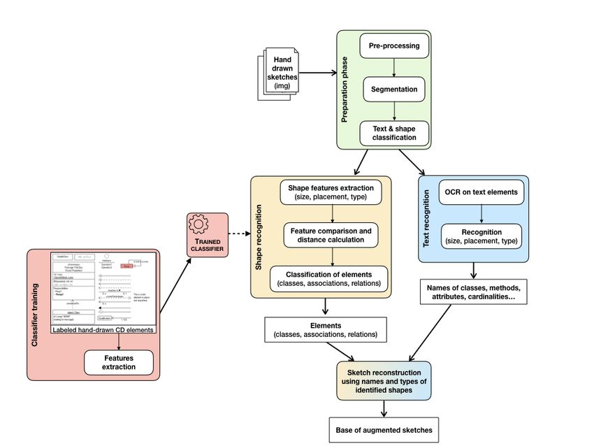
Fig. 1: Prototype advancement
V. O UR APPROACH
In [7] Chaudron and Jolak revealed their vision of a In our study, a simple example of a class diagram (Fig. 2) is
new generation of software design environments. We try to used to understand what kind of processing we need to employ.
approach this vision by raising analog sketches to the level Indeed, components of hand-drawn class diagram depend on
of project artifacts. We choose offline mode 1) to let the the way the user has drawn it. For example, boxes representing
designer uses any kind of support and 2) to not impose him yet classes and lines representing links between classes can vary
another tool to manage. To this end, analog sketches need to a lot from a user to another. In this context, extracting straight
lines using classical methods as Hough transform [11] are no
8 Application programming interface Representational State Transfer longer efficient as lines are more or less straight.As there is a line between classes, only one connected
component is obtained for the two classes and the association
between them (Fig. 4(a)). In order to separate them, connected
components are filled (Fig. 4(b)) and a morphological opening
is performed. By using the previous image as a binary mask
on image obtain in 3(b), only classes are obtained (Fig. 4(c)).
Fig. 2: Picture of a simple class diagram
To do that, OpenCV 9 and Python 10 are used to prepare
our image for extraction of text and shapes drawn in our class
diagram. Fig. 1 represents the pre-processing steps which
Fig. 5: Segmentation result of class diagram
consist in a binarization of the image (Fig. 3 (a)) followed by
a segmentation of shapes and text.
C. Segmentation
B. Shapes and text separation Finally, thanks to all step realized before, we are able to
segment a class diagram into elements representing individual
In the case of hand-drawn elements, like in Fig. 2, contours
class box (Fig. 5(a)), class box component containing the class
of class boxes are not closed. Morphological closing [35]
name (Fig. 5c) and class box component containing attributes
is used to obtain connected components (Fig. 3(b)). Suzuki
name (Fig. 5b). Classical recognition methods can be then used
algorithm [41] is then used to retrieve contours from the
to recognize shapes and classical Optical character recognition
image (Fig. 3 (c)).
(OCR) as Tesseract 11 can be used to recognize the hand-
written class name (Fig. 5).
VI. F UTURE W ORKS
A. Finalization of the sketches recognition tool
The purpose of the work presented in this section was to
elaborate the specifications of our sketch recognition mech-
anism. For the moment, we have only made a very simple
prototype to validate that it is possible to automatically extract
information from the sketch. The few tests carried out have
Fig. 3: (a) binary image, (b) connected components extracted, been promising. So we plan the future steps to continue
(c) contours extracted developing our tool as shown in Fig 6. First, we will need to
complete the segmentation of shapes and text in more complex
diagrams. Then Tesseract engine will be used to perform OCR
recognition of names, methods, attributes, cardinalities. For
shape features recognition, we will need to build a corpus of
hand-drawn class diagrams. Ho-Quang et al. [19] have built a
similar base of digitized images of class diagrams built with
UML tools and found on the internet. Our base of hand-drawn
CD diagrams will be used to train a classification algorithm an-
alyzing shape elements to extract the information concerning
size, orientation and type. Then, this trained classifier will be
Fig. 4: (a) filled shapes (b) morphological opening (c) classes able to identify elements of a CD diagram. Once completing
extracted these steps and combining their results, we hope to obtain
sketches with augmented information.
9 https://opencv.org/
10 https://www.python.org/ 11 https://github.com/tesseract-ocr/tesseractFig. 6: Overview of the entire future prototype
B. Experimentation helps to increase the use of sketches in IT projects, and if it
The goal of our work is to verify that more sketches in encourages improvement of the quality of the sketches. And
projects and our recognition and classification mechanism finally, we want to know if the engineer accepts to use and
can help to reintroduce software architecture modeling as an disseminate his sketches as documentation of its code.
effective practice in the engineering project. b) The case of a new project: In the case of a practicing
We plan to do an experimentation and evaluation of our engineer brainstorming on a new project, we experiment with
prototype with IT professionals and students. The first step is two types of engineer, the first one starts to draw sketches as
to evaluate the interest of an assisted archiving of the sketches. he used to do, the other receives help from our tool. In the
The second one is to evaluate the added value of later retrieval second case, he takes a photo of the draft of a sketch and the
in a new project. And the third one is to evaluate the added tool shows him all the corresponding sketches. Will it be a
value of the archived sketch to understand a code that the help for an engineer? And what use does the engineer have of
engineer did not write, for instance, a new team member. it?
a) Assisted archiving: We are designing our tool with c) The case of a new team member: In the same way,
ease of use in mind. We will ask the practicing software we will compare two types of engineer. The first one tries to
engineer to photograph his sketch with its smartphone. Our discover the code without help. The other selects a piece of
tool will archive the sketch recognizing the maximum of code and our tool shows him the corresponding sketches.
content semantic (shape, text, etc.) and adding context data
VII. C ONCLUSION
from other tools like the code editor, the project calendar, etc.
The first part of the evaluation is to observe the developer In this paper, we list some known reasons why docu-
using our prototype, to find out if it is easy to use and if it mentation and graphical representation are important for thesoftware to be designed and maintained. We focused on UML [14] Parisa Ghazi and Martin Glinz. Challenges of working with artifacts
models. Then we select in the literature some obstacles to in requirements engineering and software engineering. Requirements
Engineering, 22(3):359–385, Sep 2017.
the adoption of UML diagrams to accompany the software [15] Achraf Ghorbel, Aurélie Lemaitre, Éric Anquetil, Sylvain Fleury, and
development process. Our motivation is to verify the idea Eric Jamet. Interactive interpretation of structured documents: Appli-
that using hand-drawn sketches that every developer naturally cation to the recognition of handwritten architectural plans. Pattern
Recognition, 48(8):2446–2458, 2015.
does, can improve traditional development processes or agile
[16] J. Grundy and J. Hosking. Supporting generic sketching-based input
approaches. To set up experiments we elaborate a mechanism of diagrams in a domain-specific visual language meta-tool. In 29th
simply to use without adding any cognitive load to the International Conference on Software Engineering (ICSE’07), pages
developers. This mechanism uses off-line sketches recognition 282–291, May 2007.
[17] Tracy Hammond and Randall Davis. Tahuti: A geometrical sketch
techniques. We describe our simple prototype that confirms recognition system for uml class diagrams. In ACM SIGGRAPH 2006
we can automatically extract information from the sketch. Courses, SIGGRAPH ’06, New York, NY, USA, 2006. ACM.
So we plan the future steps to continue developing our tool. [18] Jorge-Ivan Herrera-Camara and Tracy Hammond. Flow2code: From
hand-drawn flowcharts to code execution. In Proceedings of the
Finally, we present as a future work different cases we want to Symposium on Sketch-Based Interfaces and Modeling, SBIM ’17, pages
experiment to check the viability of our proposition in actual 3:1–3:13, New York, NY, USA, 2017. ACM.
IT projects and to verify if our proposition really improves the [19] T. Ho-Quang, M. R. V. Chaudron, I. Samelsson, J. Hjaltason, B. Karas-
quality and effectiveness of software modeling process. neh, and H. Osman. Automatic classification of uml class diagrams from
images. In 2014 21st Asia-Pacific Software Engineering Conference,
volume 1, pages 399–406, Dec 2014.
R EFERENCES [20] Markus Kleffmann, Sebastian Rohl, Matthias Book, and Volker Gruhn.
[1] Gayane Azizyan, Miganoush Katrin Magarian, and Mira Kajko- Evaluation of a traceability approach for informal freehand sketches.
Mattsson. Survey of agile tool usage and needs. In 2011 Agile Autom. Softw. Eng., 25(1):1–43, 2018.
Conference, AGILE 2011, Salt Lake City, Utah, USA, August 7-13, 2011, [21] Andrew J. Ko, Robert DeLine, and Gina Venolia. Information needs
pages 29–38, 2011. in collocated software development teams. In 29th International Con-
[2] Sebastian Baltes and Stephan Diehl. Sketches and Diagrams in Practice. ference on Software Engineering (ICSE 2007), Minneapolis, MN, USA,
Proceedings of the 22nd ACM SIGSOFT International Symposium on May 20-26, 2007, pages 344–353, 2007.
Foundations of Software Engineering, pages 530–541, 2014. [22] Philippe Kruchten. The Rational Unified Process: An Introduction,
[3] Sebastian Baltes, Fabrice Hollerich, and Stephan Diehl. Round-trip Second Edition. Addison-Wesley Longman Publishing Co., Inc., Boston,
sketches: Supporting the lifecycle of software development sketches MA, USA, 2nd edition, 2000.
from analog to digital and back. CoRR, abs/1708.01787, 2017. [23] E. Lank, J. Thorley, S. Chen, and D. Blostein. On-line recognition
[4] Sebastian Baltes, Peter Schmitz, and Stephan Diehl. Linking sketches of uml diagrams. In Proceedings of Sixth International Conference on
and diagrams to source code artifacts. CoRR, abs/1706.09700, 2017. Document Analysis and Recognition, pages 356–360, 2001.
[5] Showmik Bhowmik, Ram Sarkar, Mita Nasipuri, and David S. Doer- [24] D. Latoza, Thomas, Gina Venolia, and Robert Deline. Maintaining
mann. Text and non-text separation in offline document images: a survey. mental models: a study of developer work habits. Proceedings of the
IJDAR, 21(1-2):1–20, 2018. 28th International Conference on Software Engineering, pages 492–501,
[6] Michel R. V. Chaudron, Werner Heijstek, and Ariadi Nugroho. How 2006.
effective is UML modeling ? - an empirical perspective on costs and [25] Seonah Lee and Sungwon Kang. What situational information would
benefits. Software and System Modeling, 11(4):571–580, 2012. help developers when using a graphical code recommender? Journal of
[7] Michel R. V. Chaudron and Rodi Jolak. A vision on a new generation of Systems and Software, 117:199–217, 2016.
software design environments. In Proceedings of the First International [26] Leonhard Lichtschlag, Lukas Spychalski, and Jan O. Borchers. Code-
Workshop on Human Factors in Modeling co-located with ACM/IEEE graffiti: Using hand-drawn sketches connected to code bases in naviga-
18th International Conference on Model Driven Engineering Languages tion tasks. In IEEE Symposium on Visual Languages and Human-Centric
and Systems (MoDELS 2015), Ottawa, Canada, September 28, 2015., Computing, VL/HCC 2014, Melbourne, VIC, Australia, July 28 - August
pages 11–16, 2015. 1, 2014, pages 65–68, 2014.
[8] Qi Chen, John C. Grundy, and John G. Hosking. SUMLOW: early [27] Nicolas Mangano, Thomas D. LaToza, Marian Petre, and André van der
design-stage sketching of UML diagrams on an e-whiteboard. Softw., Hoek. Supporting informal design with interactive whiteboards. In CHI
Pract. Exper., 38(9):961–994, 2008. Conference on Human Factors in Computing Systems, CHI’14, Toronto,
[9] Mauro Cherubini, Gina Venolia, Robert DeLine, and Andrew J. Ko. Let’s ON, Canada - April 26 - May 01, 2014, pages 331–340, 2014.
go to the whiteboard: how and why software developers use drawings.
[28] Nicolas Mangano, Thomas D. LaToza, Marian Petre, and André van der
In Proceedings of the 2007 Conference on Human Factors in Computing
Hoek. How software designers interact with sketches at the whiteboard.
Systems, CHI 2007, San Jose, California, USA, April 28 - May 3, 2007,
IEEE Trans. Software Eng., 41(2):135–156, 2015.
pages 557–566, 2007.
[10] Uri Dekel and James D. Herbsleb. Notation and representation in collab- [29] Marian Petre. UML in practice. In Proceedings - International
orative object-oriented design: an observational study. In Proceedings Conference on Software Engineering, pages 722–731, 2013.
of the 22nd Annual ACM SIGPLAN Conference on Object-Oriented [30] Mahdi Rabbani, Reza Khoshkangini, H. S. Nagendraswamy, and Mauro
Programming, Systems, Languages, and Applications, OOPSLA 2007, Conti. Hand drawn optical circuit recognition. In Proceeding of
October 21-25, 2007, Montreal, Quebec, Canada, pages 261–280, 2007. the Seventh International Conference on Intelligent Human Computer
[11] Richard O. Duda and Peter E. Hart. Use of the hough transformation to Interaction, IHCI 2015, Allahabad, India, 14-16 December 2015., pages
detect lines and curves in pictures. Commun. ACM, 15(1):11–15, 1972. 41–48, 2015.
[12] Ana M. Fernández-Sáez, Danilo Caivano, Marcela Genero, and Michel [31] James Rumbaugh, Ivar Jacobson, and Grady Booch. Unified Modeling
R. V. Chaudron. On the use of UML documentation in software Language Reference Manual, The (2Nd Edition). Pearson Higher
maintenance: Results from a survey in industry. In 18th ACM/IEEE Education, 2004.
International Conference on Model Driven Engineering Languages and [32] Ugo Braga Sangiorgi, François Beuvens, and Jean Vanderdonckt. User
Systems, MoDELS 2015, Ottawa, ON, Canada, September 30 - October interface design by collaborative sketching. In Designing Interactive
2, 2015, pages 292–301, 2015. Systems Conference 2012, DIS ’12, Newcastle Upon Tyne, United
[13] Florian Geyer, Jochen Budzinski, and Harald Reiterer. Ideavis: a hybrid Kingdom, June 11-15, 2012, pages 378–387, 2012.
workspace and interactive visualization for paper-based collaborative [33] Ken Schwaber. Scrum development process. In Jeff Sutherland, Cory
sketching sessions. In Nordic Conference on Human-Computer Interac- Casanave, Joaquin Miller, Philip Patel, and Glenn Hollowell, editors,
tion, NordiCHI ’12, Copenhagen, Denmark, October 14-17, 2012, pages Business Object Design and Implementation, pages 117–134, London,
331–340, 2012. 1997. Springer London.[34] T. Sedano, P. Ralph, and C. Péraire. Software development waste. In
2017 IEEE/ACM 39th International Conference on Software Engineer-
ing (ICSE), pages 130–140, May 2017.
[35] Jean Serra. Image Analysis and Mathematical Morphology. Academic
Press, Inc., Orlando, FL, USA, 1983.
[36] David Socha and Josh D. Tenenberg. Sketching and conceptions
of software design. In 8th IEEE/ACM International Workshop on
Cooperative and Human Aspects of Software Engineering, CHASE 2015,
Florence, Italy, May 18, 2015, pages 57–63, 2015.
[37] Dan Song, Dongming Wang, and Xiaoyu Chen. Retrieving geometric
information from images: the case of hand-drawn diagrams. Data Min.
Knowl. Discov., 31(4):934–971, 2017.
[38] Christoph Johann Stettina and Werner Heijstek. Necessary and ne-
glected?: An empirical study of internal documentation in agile software
development teams. In Proceedings of the 29th ACM International
Conference on Design of Communication, SIGDOC ’11, pages 159–
166, New York, NY, USA, 2011. ACM.
[39] Margaret-Anne D. Storey, Alexey Zagalsky, Fernando Marques Figueira
Filho, Leif Singer, and Daniel M. Germán. How social and communi-
cation channels shape and challenge a participatory culture in software
development. IEEE Trans. Software Eng., 43(2):185–204, 2017.
[40] Harald Störrle. How are conceptual models used in industrial soft-
ware development?: A descriptive survey. In Proceedings of the 21st
International Conference on Evaluation and Assessment in Software
Engineering, EASE 2017, Karlskrona, Sweden, June 15-16, 2017, pages
160–169, 2017.
[41] Satoshi Suzuki and KeiichiA be. Topological structural analysis of
digitized binary images by border following. Computer Vision, Graphics,
and Image Processing, 30(1):32 – 46, 1985.
[42] B. Vesin, R. Jolak, and M. R. V. Chaudron. Octouml: An environment for
exploratory and collaborative software design. In 2017 IEEE/ACM 39th
International Conference on Software Engineering Companion (ICSE-
C), pages 7–10, May 2017.
[43] Jagoda Walny, Jonathan Haber, Marian Dörk, Jonathan Sillito, and
M. Sheelagh T. Carpendale. Follow that sketch: Lifecycles of diagrams
and sketches in software development. In Proceedings of the 6th IEEE
International Workshop on Visualizing Software for Understanding and
Analysis, VISSOFT 2011, Williamsburg, VA, USA, September 29-30,
2011, pages 1–8, 2011.
[44] Dustin Wüest, Norbert Seyff, and Martin Glinz. Flexisketch: A mobile
sketching tool for software modeling. In Mobile Computing, Applica-
tions, and Services - 4th International Conference, MobiCASE 2012,
Seattle, WA, USA, October 11-12, 2012. Revised Selected Papers, pages
225–244, 2012.
[45] Dustin Wüest, Norbert Seyff, and Martin Glinz. FLEXISKETCH
TEAM: collaborative sketching and notation creation on the fly. In 37th
IEEE/ACM International Conference on Software Engineering, ICSE
2015, Florence, Italy, May 16-24, 2015, Volume 2, pages 685–688, 2015.You can also read