VFS 2 Video Fiber Scope User's Guide
←
→
Page content transcription
If your browser does not render page correctly, please read the page content below

VFS 2 Video Fiber Scope
            User’s Guide

Test & Inspection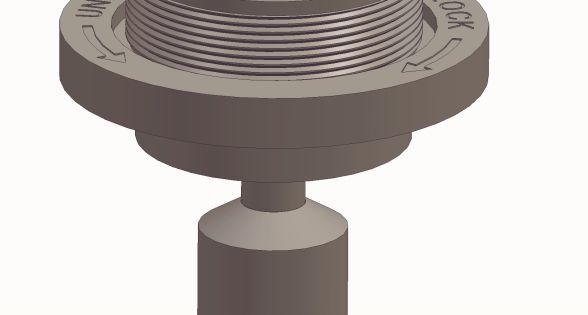
VFS 2 Video Fiber Scope
            User’s Guide

Test & Inspection

         © 2004-2010, AFL Telecommunications, all rights reserved. VFS2-00-1000 Revision B 2010-07-30
                                                       Specifications are subject to change without notice.
Limited Warranty
One Year Limited Warranty any applicable specifications including full
All Noyes products are warranted against compliance with all essential requirements of
defective material and workmanship for a all applicable EU Directives.
period of one year from the date of shipment
to the original customer. Any product found to Returning Equipment
be defective within the warranty period will be To return equipment, please contact Noyes
repaired or replaced by Noyes. In no case will to obtain additional information and a Service
Noyes liabilities exceed the original purchase Request (S.R.) number. To allow us to serve
price of the product. you more efficiently, please include a brief
description specifying the reason(s) for the
Exclusions return of the equipment.
The warranty on your equipment shall not apply AFL Telecommunications
to defects resulting from the following:
Noyes
• Unauthorized repair or modification 16 Eastgate Park Road
• Misuse, negligence, or accident Belmont, NH 03220
Phone: 800-321-5298
603-528-7780
CE Information
Fax: 603-528-2025
These instruments have been
designed and tested to comply
with the relevant sections ofContents
Safety Information............................................................ iii
Section 1: General Information
Contacting Noyes Customer Service . ............................... 1
Unpacking and Inspection................................................. 1
Feature Overview............................................................. 2
Required Accessories....................................................... 3
Section 2: Functional Description
VFS 2 Inspection Probe.................................................... 4
VFS 2 Display Unit............................................................ 6
VCP 1 Video Capture Port................................................. 8
Section 3: Operating Instructions
Installing Adapter Tips...................................................... 10
VFS 2 Adapter Tips.......................................................... 12
Using Adapter tips with blue Delrin end piece................ 12
Using the VFS 2 universal cap adapter.......................... 13
Connecting the VFS 2 Probe to a Display or VCP 1 unit...... 14
Focusing.......................................................................... 15
Inspecting Connectors with Probe and Display................... 16
iTransferring images to a PC.......................................... 16
Inspecting Connectors with Probe and VCP 1 Unit.............. 18
Examples of Fiber Images ................................................ 19
Section 4: General Care and Maintenance
General Care.................................................................... 20
Lens Care........................................................................ 20
To inspect the lens....................................................... 21
To clean the lens.......................................................... 21
Charging the VFS 2 Display Battery................................... 22
Section 5: Specifications
Optical Specifications................................................... 23
VFS 2 Probe Specifications........................................... 23
VFS 2 Display Specifications......................................... 24
VCP 1 Video Capture Port Specifications....................... 25
iiSafety Information
WARNING! Use only the specified AC adapter. Use of another type of AC adapter can
! damage the instrument and create the danger of fire and electrical shock.
WARNING! To avoid the danger of fire and electrical shock:
!
• Never use a voltage that is different from that for which the AC adapter is rated.
• Do not plug the unit into a power outlet that is shared by other devices.
• Never modify the power cord or excessively bend, twist, or pull it.
• Do not allow the power cord to become damaged. Do not place heavy objects on the
power cord or expose it to heat.
• Never touch the AC adapter while your hands are wet.
• Should the power cord become seriously damaged (internal wiring exposed or shorted),
contact the manufacturer to request servicing.
CAUTION! To avoid serious eye injury, never look directly into optical outputs of fiber
! optic network equipment, test equipment, patch cords, or test jumpers. Always assume
that optical outputs are on.
CAUTION! The VFS 2 should be protected from accidental drops at all times. A drop on
! the tip end of the probe can cause damage which would prevent use of the probe. Drops
iiiin other areas can lead to misalignment or damage as well. If the fiber end-face image
appears to be distorted or is off the display screen, the unit should be returned to the
factory for repair and/or calibration.
NOTICE! The VFS 2 Probe, VFS 2 Display , and VCP 1 Video Capture Port contain no
! user-serviceable components inside. Except for changing batteries in the VFS 2 Display,
these instruments must be returned to Noyes for repair. Opening instruments shall void
the factory warranty.
IMPORTANT! Although the VFS 2 Probe has been designed to operate in a wide range
of environmental conditions, care should be taken when handling or storing any precision
optical equipment such as the VFS 2 probe.
ivSection 1: General Information
The purpose of this User’s Guide is to explain how to use and maintain Noyes test equipment.
Please check our web site at www.AFLtele.com (click on Products > Noyes Test & Inspection)
for updates to this manual, software updates, and additional application information. If you have
any questions about your instruments and recommended accessories, or if you need technical or
sales support, please contact Noyes Customer Service.
Contacting Noyes Customer Service
You may call Noyes Customer Service between 8 a.m. and 5 p.m., United States Eastern Time,
as follows:
Phone: 800-321-5298
603-528-7780
Fax: 603-528-2025
Web: www.AFLtele.com (click on Products > Noyes Test & Inspection)
Unpacking and Inspection
These instruments have been carefully packed in accordance with standard shipping procedures.
Examine the equipment for damage that may have occurred during shipment. If you find any
damage, please contact Noyes.
1Feature Overview
The VFS 2 is a small extremely versatile Video Fiber Scope designed for the inspection of fiber
optic connectors and couplers. The VFS 2 retains the superior image quality associated with
Noyes inspection products. The unique “optical-knuckle” allows the user to orient the VFS 2
Probe head in virtually any direction. This feature allows the user to view connectors that may be
located in tight or difficult locations. With a Probe head length of less than 8 cm (3.25”), access
into crowded/ cramped quarters becomes a reality.
The VFS 2 resolves ¾ micron scratches keeping with our standard of quality end-face images.
This unit is designed for one-handed operation and with the “optical-knuckle” feature, the unit is
equally easy for both right and left handed individuals.
The new precision adapter tips for the VFS 2 Inspection Probe ease getting fiber images in the
viewing area. These tips ensure the optics will view into the alignment sleeve, thus simplifying
centering the fiber. An adapter tip must be left on the Probe at all times to protect the objective
lens.
The VFS 2 Inspection Probe may be paired with the VFS 2 high-resolution 3.5” (diagonal) Display
or the VCP 1 Video Capture Port. The VFS 2 Display is a compact, portable unit that provide hours
of continuous operation as well as rechargeable battery.
The VCP 1 Video Capture Port allows the user to inspect fiber optic end-faces and capture viewed
images on a PC. The VCP 1 simply attaches via a standard USB A plug connector to a computer
and offers “plug and play” installation. With the supplied easy-to-use software, fiber end images
can be saved and organized for analyzing, printing, and archiving.
2To ensure proper operation, it is important to keep all optical connections and surfaces free
from dirt, oils, or other contaminants. Proper cleaning techniques must be performed on fiber
connectors, connector adapters, and optical ports. Refer to the section on maintenance for more
information on cleaning methods. Always replace protective dust caps.
Required Accessories
The VFS 2 Inspection Probe requires an adapter tip that matches the connector type to be inspected.
Adapter tips for all standard connector types are available. For an up-to-date list of adapter tips
contact Noyes, or visit our web site at www.AFLtete.com (click on Products > Noyes Test &
Inspection > Accessories & Services).
A supply of cotton tipped swabs (single or double ended) and commercial lens cleaner is
recommended for cleaning the optical port on the Probe. Also, a can of filtered compressed air
is useful for blowing contaminates out of connector adapter tips.
For cleaning connector end-faces on test jumpers and in fiber frames or adapters, Noyes
recommends using our exclusive FCC2 non-hazardous cleaning fluid and CCT molded cleaning
tips. CCT cleaning tips and FCC2 cleaning fluid may be combined into FCP1 fiber optic cleaning
kits. Noyes offers a complete selection of FCP1 cleaning kits for field cleaning. The FCP1 Series
of kits delivers compact, safe, easy to use, reliable cleaning for all types of fiber optic connector
end-faces.
Visit our web at www.AFLtele.com (click on Products > Noyes Test & Inspection > Cleaning
Supplies) for more information.
3Section 2: Functional Description
VFS 2 Inspection Probe
The VFS 2 is a small extremely versatile video fiber scope with a Probe head length of less than
8 cm (3.25”) specially designed for inspecting fiber oiptic terminations that may be located in
tight or difficult locations.
1 Probe head - The VFS 2 rotating Probe head may be positioned to any angle. The full
360 degree rotation of the head allows unparalleled access to connectors and bulkhead
adapters.
2 Lens tube - This tube contains the internal lens. Also, it accepts various precision adapter
tips.
3 Optical port - This is the internal lens.
4 Adapter tip - The VFS 2 Probe requires an adapter tip that matches the connector type to
be inspected. Select the appropriate adapter and mount it on the Lens tube, replacing the
universal tip that should be kept on the VFS 2 Probe at all other times for protection. The
precision adapter tips for the VFS 2 ease getting fiber images in the viewing area. These tips
ensure the optics will view into the alignment sleeve, thus simplifying centering the fiber.
5 Focus wheel - Used for focusing adjustments. Turn slowly the knurled focus wheel until the
fiber end-face image is viewed in sharp focus. If needed, reverse the rotation of the focus
wheel and continue to focus until the best resolution and contrast of the displayed fiber end-
4face image is achieved.
6 Modular RJ11 connector - Used to connect the VFS 2 Probe to the VFS 2 Display unit or
Video Capture Port (VCP 1).
5
1
2
3
6
4
Figure 2-1: VFS 2 Inspection Probe
5VFS 2 Display Unit
The VFS 2 Display unit is a portable high-resolution 3.5-inch video display designed to interface
with the VFS 2 Probe. The VFS 2 Probe in conjunction with the VFS 2 Display allows inspecting
fiber optic connectors without need of removing them from their bulkhead adapters.
1 VFS 2 Display unit screen - 3.5” (8.9 cm) diagonal color TFT-LCD display. Provides images
equivalent to 250x magnification of fiber optic terminations being inspected with the VFS 2
Probe.
2 [Probe] port - The RJ11 jack provides power to and receives signal from the VFS 2 Inspection
Probe.
3 [Video out] port - This port provides connection to an external monitor or to a PC via an
interface cable.
4 Battery status indicators: - Identify battery conditions as follows:
Red indicator [ON] - Low battery condition. Battery requires charging.
Green indicator [BLINKING] - Battery is charging.
Green indicator [ON] - Battery is fully charged.
5 [Power] port - This is the interface for the AC power adapter/charger. [Power] port provides
AC power to the Display unit for operation and battery recharging. When an AC adapter/
charger is plugged in, the battery will be charged whether the power switch is ON or OFF.
6 [Power] switch - Turns the VFS 2 Display unit and VFS 2 Probe On or Off.
61
NOYES
AFL Telecommunications
VFS2 VIDEO FIBER SCOPE DISPLAY
NOYES
AFL Telecommunications
VFS2 VIDEO FIBER SCOPE DISPLAY
T
OU
E
EO
OB
/
G
V
VID
PR
TCH
18
OU
E
EO
OB
/
G
V
VID
PR
CH
18
2 6
3 5
4
Figure 2-2: VFS 2 Video Display (front and bottom views)
7VCP 1 Video Capture Port
The VCP 1 Video Capture Port is an interfacing module that provides high-speed composite video
signal to a digital format conversion for capturing and displaying video data on a PC. The VCP
1 simply attaches via a standard USB connector to your computer and offers “plug and play”
installation.
When used in conjunction with the VFS 2 Probe, the VCP 1 Video Capture Port allows the user
to inspect fiber optic end-faces and capture viewed images on a computer. With the supplied
easy-to-use software, fiber end images can be saved and organized for analyzing, printing, and
archiving. For a complete description of the Video Capture software, refer to the User’s Guide
supplied with the software.
1 [Probe] port located on the top panel - [Probe] port - the RJ11 jack provides a video input
for a composite video signal from the VFS 2 Probe. The VFS 2 modular connector (RJ11) to
be plugged into the VCP 1 [Probe] port
2 [Active] indicator - The red LED will turn on when the video capture software (supplied with
the VCP 1 unit) identifies the VCP 1 unit on the USB line.
3 [Snap shot] button - This is the video capture button for single shot video capture. Press
this button to capture the displayed image.
4 USB A plug connector - Used to connect the VCP 1 to a PC.
8VFS 2 modular connector - RJ11
1
Active
2
3
Snap Shot
VCP1
VIDEO CAPTURE
PORT
NOYES
AFL Telecommunications
4
Figure 2-3: VCP 1 Video Capture Port
9Section 3: Operating Instructions
This section describes the operation of the VFS 2 Probe and Display or VCP 1 unit for inspecting
installed fiber optic connectors.
Installing Adapter Tips
Figure 3-1 illustrates the following procedures.
1 Select the appropriate adapter tip that matches the connector type to be inspected.
2 Before installing the selected adapter tip, remove the universal adapter tip supplied with the
VFS 2 Inspection Probe (or any other installed tip).
Note: In order to distinguish an adapter tip from the internal lens tube, each tip has a knurled
(grooved) finger grip area near the base.
3 To unscrew the installed adapter tip from the end of the VFS 2 Probe, twist it with a
counterclockwise motion as viewed from the adapter tip end.
4 Gently slip the adapter tip off the end of the internal lens tube and return it to the provided
storage container.
5 Be sure that the lens tube is retracted fully by turning the focus wheel counterclockwise as
viewed from the tip end.
6 Gently slide the adapter tip to be installed over the lens tube being careful not to contact the
10small lens opening.
7 Twist the adapter tip clockwise in order to screw it into the end of the VFS 2 Probe (FINGER
TIGHT ONLY!).
Internal lens tube
Adapter tip Focus wheel
Knurled area
Tip base Lens opening
Figure 3-1: Adapter tip installation
11VFS 2 Adapter Tips Using Adapter tips with blue Delrin end piece Adapter tips, which have a definite orientation such as the ASC shown in the illustration below, may have the blue end piece, which may be rotated to a convenient position. To rotate the blue end piece: 1 Insert the blue end piece into the connector being inspected. 2 Hold the VFS 2 Probe and the black [base] portion of the adapter tip in one hand. 3 Hold the blue end piece and connector Blue end piece being inspected in the other hand. [Base] portion of 4 The Probe and the [base] may now be the Adapter tip rotated as one unit while the blue end piece is prevented from rotating. Example: It may be convenient to have the Probe body pointed downward when inserted into a connector patch panel. Re-adjust as needed for different situations. Note: The blue end-piece should not be removed from the adapter tip. When removing Hold the Probe and the adapter tip from the VFS 2 Probe, be sure the [base] in one hand to unscrew the black [base] as usual. 12
Using the VFS 2 universal cap adapter
The VFS 2 universal cap adapter provides expanded options for inspection a wide variety of connector
types. It must be handled with additional care beyond that given to the standard VFS 2 due to mechanical
considerations. Please follow the instructions below when installing the universal cap adapter to the
VFS 2 Probe and also when attaching each Noyes adapter cap to the universal cap adapter.
1 Thread the universal cap adapter into the VFS 2 Probe, and then tighten
    it using the knurled area at the Probe end (FINGER TIGHT ONLY!).
2 When attaching a Noyes adapter cap to the universal cap adapter, hold
    the straight section of the universal cap adapter firmly as each Noyes
    adapter cap is gently screwed onto the end.
3 Once installed, each Noyes adapter cap can be “panned” in any X-Y
    direction as follows:
     • Gently twist the engraved lock ring toward the unlock direction until
        it is only lightly snugged down.
     • As needed, move the installed Noyes adapter cap to center either
        the fiber end or to inspect adjacent areas of the ferrule.
     • If desired, the lock ring can then be gently turned in the lock direction
        to hold the position.
4 Removal of a Noyes adapter cap or the universal cap adapter itself is the reverse of the directions
    provided above.
Note: Use caution not to rotate the probe head against the probe body while the universal cap adapter
is attached.
                                                                                                    13
Connecting the VFS 2 Probe to a Display or VCP 1 unit
1 Plug the modular connector (RJ11) at the end of the VFS 2 coiled cord into the mating RJ11
jack - Probe port on the Display or VCP 1 unit.
2 Note the orientation of the VFS 2 modular connector as there is a tab that must be aligned
on the connector and mating RJ11 jack.
3 To unplug the VFS 2 Probe, gently squeeze the tab on the modular connector and pull it straight
out from the mating RJ11 jack - Probe port.
mating RJ11 jack
on the Display or
VCP 1 unit
modular connector
at the end of the
VFS 2 Probe coiled
cord tab
Figure 3-2: Connecting the VFS 2 Probe to a Display or VCP 1 unit.
14Focusing
1 The fiber end-face image is brought into sharp focus by turning the knurled, silver focus wheel
located in the probe head.
2 At some point, you may see an image of the light source used in the scope. Continue turning
the focus wheel slowly until the fiber end-face is viewed in sharp focus.
3 Reverse direction if the focus wheel reaches the end of its range without obtaining an
image.
Note: A good method for achieving optimum focus is to approach the best focus from one
direction of motion of the focus wheel. Also, be sure that the VFS 2 Probe tip is fully inserted
into the connector under inspection, or that the connector ferrule is fully inserted into the tip
for universal tips or other tip styles.
focus wheel probe head.
Figure 3-3: Focusing
15Inspecting Connectors with Probe and Display 1 Select the appropriate adapter tip that matches the connector to be inspected. 2 Place the selected adapter tip on the internal lens tube. 3 Plug the VFS 2 Probe cord into the probe port on the Display unit. 4 Insert the adapter tip into the connector to be inspected. If needed, the Probe head rotates to inspect those hard to reach connectors. 5 To bring the fiber end-face image into view, turn the focus wheel slowly until the fiber end-face is viewed in sharp focus. 6 If you are unable to bring the image into focus, check that the adapter tip is screwed on tightly, then try again (FINGER TIGHT ONLY!). Transferring images to a PC Depending upon the application, it may be desirable to produce documentation of the inspected connectors. The VFS 2 Display unit allows transferring of the displayed image to a computer. This process requires a video cable and a computer that is equipped with an external or internal video digitizer capable of handling NTSC signal. To send the video signal from the VFS 2 Display unit to a computer: 1 Plug one end of the video cable into the Video Out port on the VFS 2 Display and the other end into the Video In port on the digitizer. 16
2 Insert the VFS 2 Probe into the connector to be inspected. If needed, the Probe head rotates
  to inspect those hard to reach connectors.
3 To bring the fiber end-face into view, turn the focus wheel slowly until the fiber end-face is
  viewed in sharp focus.
4 If you are unable to bring the image into focus, check that the adapter tip is screwed on tightly,
  then try again (FINGER TIGHT ONLY!).
5 The VFS 2 Display Unit is now rerouting the video signal to the digitizer. Refer to the digitizer's
  user's guide for additional information on capturing, saving, and printing the displayed connector
  image.

                                                                                                    17
Inspecting Connectors with Probe and VCP 1 Unit
1 From the supplied CD-ROM, install the driver and Video Capture software to your computer.
Note: For a complete description of the Video Capture software, refer to the User’s Guide
supplied with the software.
2 With the Video Capture software installed, plug the VCP 1 Video Capture Port into the USB
port.
3 With the VCP 1 connected to the USB port, plug the VFS 2 Probe into the RJ11 jack - Probe
port on the VCP 1.
4 Open the Video Capture software and select acquire image.
5 The red LED - [Active] indicator on the VCP 1 will turn on when the software identifies the
VCP 1 unit on the USB line.
6 Insert the VFS 2 Probe into the connector to be inspected.
7 Observe the fiber image on the screen and focus the image by rotating the focus wheel on
the VFS 2 Probe.
8 To capture the displayed image press the [Snap shot] button on the VCP 1 or click on the
[Capture] button on the screen.
18Examples of Fiber Images
Various examples of fiber
end-face images ranging
from excellent to very poor
conditions.
Excellent condition Uncleaned, lint or dust
Scratches and dirt Severely scratched face Cleaning residue, water
or alcohol
19Section 4: General Care and Maintenance
General Care
The VFS 2 Inspection Probe is a precision optical device. As such, there are certain parts of the
Probe that cannot be protected from abuse due to the small geometry required to interface with
modern fiber optic connectors.
The VFS 2 should be protected from accidental drops at all times. A drop on the tip end of the
Inspection Probe can cause damage, which would prevent use of the Probe. Drops in other areas
can lead to misalignment or damage as well. If the fiber end-face image appears to be distorted or
is off the display screen, the unit should be returned to the factory for repair and/or calibration.
Lens Care
Contact with the small lens at the end of the Probe lens tube should be avoided. Adapter tips
should be installed by gently sliding over the end of the lens tube as mentioned earlier. This action
will not harm the lens.
If the face of the small lens becomes contaminated, the image quality will be degraded.
The lens must be kept free from dirt or other contaminants. It should be cleaned as needed using
the instructions on the following page.
! CAUTION! Remove Probe power for the following procedures.
20To inspect the lens
1 Hold the VFS 2 Probe at an angle to room lighting.
2 Examine the lens with a magnifying glass.
3 If the lens surface does not appear to be clean and free of fingerprints, dust, or other
contaminants, it should be cleaned.
To clean the lens
To access the lens, first remove the adapter tip that may be installed. Lens removal is not
recommended.
1 To remove the installed adapter tip, twist it with a counterclockwise motion as viewed from
the adapter tip end.
2 Gently slip the adapter tip off the end of the internal lens tube.
3 Using a double ended cotton swab (such as a Q-tip) or two single ended swabs, apply a single
drop of lens cleaner to one end of a swab. Touch it to the lens, apply gentle pressure and
rotate gently several times.
4 Immediately, use the dry end of a swab to repeat the action. This cleans the lens and removes
remaining moisture.
5 Using a can of filtered compressed air (held vertically), blow out any contaminants from the
adapter tip
6 Once completed, replace the adapter tip over the internal lens tube being careful not to contact
the small lens opening. Twist the adapter tip clockwise in order to screw it into the end of the
VFS 2 Probe. Finger tighten only!
21Charging the VFS 2 Display Battery
When the “Low Battery” indicator illuminates RED, the internal battery requires recharging. To
recharge the internal battery, connect the AC power adapter/charger to the AC adapter/charger
port and a wall outlet. The battery will charge in 4 hours.
NOYES
AFL Telecommunications
VFS2 VIDEO FIBER SCOPE DISPLAY
T
OU
E
EO
OB
/
G
V
VID
PR
CH
18
Battery status indicators:
“Low Battery” indicator AC adapter/charger port
Red LED ON - low battery Provides AC power to the
condition; battery requires Display unit for operation and
charging. battery recharging.
Green LED BLINKING - battery
is charging.
Green LED ON - battery is fully
charged.
Figure 4-1: Charging the VFS 2 display battery.
22Section 5: Specifications
Optical Specifications
Field of view 500 microns diagonal
(300 microns vertical, 400 microns horizontal)
Magnification 180x on 3.5” display
Resolution ¾ micron scratch
Video output NTSC
VFS 2 Probe Specifications
Operating temperature 0 to +50°C
Storage temperature -20 to +60°C
Humidity 0 to 90% (non-condensing)
Probe weight 0.4 lb (0.2 kg)
Probe body size (L x W x D) 6.3 x 1.3 x 1.3 in (15.9 x 3.3 x 3.3 cm)
Probe head size (with FC adapter), (L x W x D) 3.1 x 1.0 x 0.6 in (7.9 x 2.5 x 1.5 cm)
Specifications are subject to change without notice.
23VFS 2 Display Specifications
Display screen size 3.5 inch TFT NTSC
Display package with protective boot size 9.0 x 2.0 x 4.7 in (22.9 x 5.1 x 11.9 cm)
Weight 2 lb (0.9 kg)
Power Li-Ion battery pack or AC adapter
Battery life with VFS 2 probe > 4 hours
Operating temperature 0° to 50° C
Storage temperature -20 to +60°C
Humidity 0 to 90% RH non-condensing
Li-Ion battery pack charging temperature -10 to +45°C
Li-Ion battery pack recharging time 4 hours
AC Power Adapter AC Input :100 to 240 V, 50 – 60 Hz, 1A
DC Output : 18 V, 2.5 A
Specifications are subject to change without notice.
24VCP 1 Video Capture Port Specifications
Interface type USB
Operating system Windows 98 / 98SE / ME / 2000 / XP
Video input Noyes RJ11 connector
Output USB Standard (VCP 1 is a Twain compatible device using
supplied software)
Analog video format NTSC or PAL
Video capture resolution 640 x 480 pixels
Snap shot Single button to capture still images at 640 x 480 pixels
Video capture format(s): JPEG
Power source 5VDC @500 mA (max) through USB port to 6 foot cord
USB data bandwidth 4Mbps - 8Mbps isochronous
Weight 0.25 lb (0.11 kg)
Size (L x W x D) 4.0 x 2.2 x 1.0 in (10.2 x 5.6 x 2.5 cm)
Specifications are subject to change without notice.
25Thank you for choosing Noyes Test & Inspection
N OY E S
16 Eastgate Park Road ISO
Belmont, NH 03220
9001
Phone: 800-321-5298 C E RT I F I E D
603-528-7780
Fax: 603-528-2025
www.AFLtele.com/go/Noyes
Test & InspectionYou can also read