COMMERCIAL SILICON FOR GIGABIT COMMUNICATION OVER SI-POF
←
→
Page content transcription
If your browser does not render page correctly, please read the page content below
COMMERCIAL SILICON FOR GIGABIT
COMMUNICATION OVER SI-POF
O. Ciordia(1), C. Esteban(1), C. Pardo(1), R. Pérez de Aranda(1)
1: Knowledge Development for POF S.L. (KDPOF), Ronda de Poniente 16, Tres Cantos, Madrid. Spain
Corresponding author: o.ciordia@kdpof.com
Abstract: This paper describes KDPOF´s commercial portfolio of gigabit silicon for communication systems over
SI-POF. The targeted markets are described along with their key performance needs. The gigabit portfolio of prod-
ucts is presented with a sample of typical applications. The paper reviews briefly the technology and performance
behind the silicon core, which are common to all KDPOF commercial products, with special emphasis on the stand-
ard compliant features.
Keywords: Spectrally efficient communication. Gigabit Standard. Commercial Silicon. Commercial products. Inte-
grated circuit. POF.
1. Introduction
KDPOF will release to market in Q1 2013 the first Application-Specific Standard Product (ASSP) to comply with
the VDE v 0885-763 specification (announced in [1]). This silicon will be the first member of a family of products
from KDPOF targeted to key POF markets: commercial (home and SOHO), industrial and automotive.
The needs and projections of key customer segments have been taken into account in developing the product re-
quirements. After thorough market research activities, and thanks to the power and flexibility of the VDE specifica-
tion, this first ASSP for the commercial market will incorporate key features that will enable product integrators to
offer, in addition to reliable and stable true Gigabit data speed, key customer demanded features like reduced power
consumption and diversity of data interfaces like RGMII and SGMII, at a competitive price.
KDPOF has developed a family of devices that implement the key features of the VDE specification, with outstand-
ing performance built around the following:
Channel Equalization following the Tomlinson-Harashima Precoding [4, 5].
Channel Coding based on Multilevel Coset Coding (MLCC) [3]. Based on low-cost binary component
codes, MLCC provides a high coding gain FEC scheme with low complexity hardware implement-ability for
mid and high spectral efficiencies. The MLCC configurable spectral efficiency property preserves constant
coding gain.
Frame Structure for continuous adaptation and tracking enables a low-cost implementation in receivers of
timing recovery, non-linear channel estimation and equalization. It enables for very fast and robust link start-
up.
Energy Efficient Ethernet based on low-power modes [2].
2. Markets
Well known for its high reliability in very harsh environments, Plastic Optical Fiber is widely used in the industrial
market for field buses and in the automotive industry for its information and entertainment buses (infotainment).
Leveraging success in these markets, POF is being installed in home and small office networks, the youngest and
fastest growing markets for POF.
Now, and thanks to the new Gigabit family of ASSP for POF, the KD1000 family, new horizons open up for POF in
these markets.
Key features of KD1000 are:
Open and Flexible Interfaces: Ethernet xGMII and SerDes, for easy connectivity to an Ethernet MAC or
PHY
Backwards Compatibility: For current IEEE 802.3 100BASE-FX based POF implementations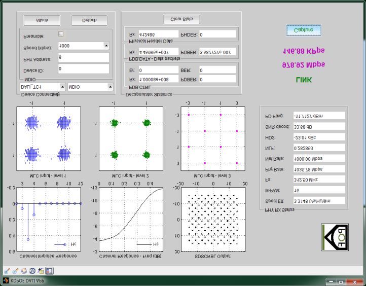
Packaging: 88-pin QFN
Sensitivity: Up to -21 dBm for 1 Gbps at 50 m of standard A4a.2 SI-POF with red LED
Technology: 65 nm, low-power CMOS
Power: < 1 W/port (including optoelectronics); advanced power management; single supply 3.3 V
The KD1000 family comprises several devices that incorporate different interface configurations like RGMII, RMII,
MII and/or SGMII and SerDes 1000BASE-X as well as PHY and MAC functionalities. OTP configuration is an
option for large volumes with I2C EEPROM configuration as a family default.
Market Product Data Interfaces Comments
KD1001 RGMII
KD1002 SGMII, SerDes Optimized for high-density switches and SFPs
Commercial
1000BASE-X
KD1100 2 x S/RGMII Switching and bonding capabilities
KD1011 RGMII, RMII, MII Industrial grade and temperature range
Industrial KD1012 SGMII, SerDes Optimized for long reach (100 Mbps, >100 m)
100BASE-X applications
KD105x Ethernet (xGMII) Optimized for automotive quality grade, temper-
P2P video (DVP) ature range and EMC
Wake-up capability
Automotive
Real Time (time stamping, PTP, SyncE) support
Full duplex over single POF operation mode
ASIL>3 safety grade
Table 1: KD1000 family of ASSP.
2.1. Commercial market
Commercially available products in the market today provide data links of only 200 Mbps up to 50 m over standard
SI-POF. The typical application for Gigabit POF within the home is as a backbone for the home network.
Providing data rates of more than 1 Gbps and an assured Quality of Service (QoS) to every device in the home, the
new family of ASSP offer a future-proof solution and an excellent alternative for the distribution of present and fu-
ture multimedia services as well as data sharing within the home or small office. These features are ideally suited for
emerging IPTV and digital video services, where the Quality of Experience (QoE) and guaranteed data-rate are the
most important factors for a successful deployment.
Members of the KD1000 family for the commercial market include the KD1001 and the KD1002. The difference
between the two devices is the data interface offered to the MAC side (RGMII and SGMII, respectively).
The KD1001, a fully integrated Gigabit POF Ethernet transceiver, has a small footprint and is optimized for low-
power. This new transceiver implements the physical layer of the VDE v 0885-763 HS-BASE-P (1000BASE-P and
xGBASE-P) to transmit data on standard SI-POF, MC-POF or PCS. It is manufactured using a 65nm CMOS pro-
cess, which offers the best performance, lowest cost, and lowest power for Gigabit POF solutions.
With its SGMII and SerDes 1000BASE-X Ethernet interface, the KD1002 enables SFP applications implementing
Gigabit POF connectivity. Moreover, high-density switches can incorporate Gigabit POF ports thanks to this mem-
ber of the KD1000 family. With a commercial temperature range and backwards compatibility with legacy IEEE
100BASE-FX installations, the KD1002 is an ideal product for home and SOHO networks.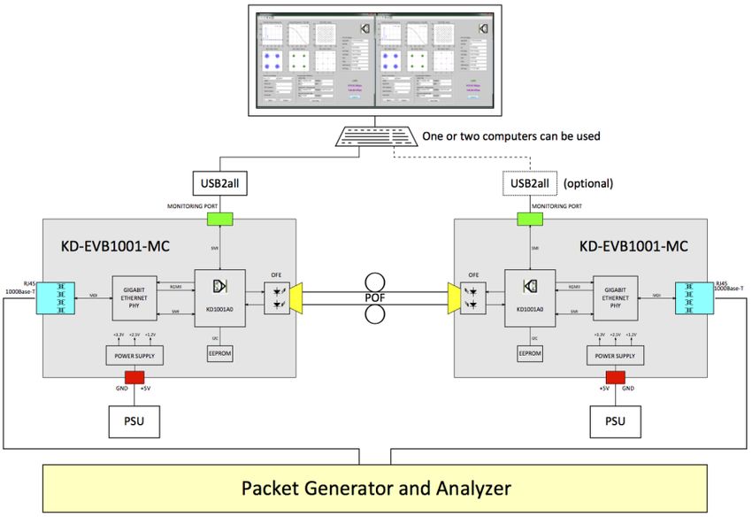
2.2. Industrial
Operating in industrial environments (-40 ºC to 85 ºC), the ruggedized members of the KD1000 family, the KD1011
and KD1012, provide a greater coverage for Fast Ethernet installations throughout the factory floor. With its native
capacity achieving modulations and seamless component optimization, KDPOF technology provides Fast Ethernet
(100 Mbps) over SI-POF links of up to more than 150 meters following annex 100BASE-P of the VDE specification
and using off-the-shelf red LEDs and connectors. This translates into a true and effective capacity upgrade of the
existing industrial buses while maintaining the installed low-cost POF infrastructure.

2.3. Automotive
Future KD1000-family automotive products will be able to provide a physical layer of 1 Gbps to networking needs
within the car that is fully compatible with the same fiber, connectors and optoelectronics components currently
installed in lower speed networks. In addition, due to specific features such as remote wake-up, Precision Time Pro-
tocol (IEEE1588) and SyncE, KDPOF´s automotive ASSP are suitable for the implementation of ADAS (Advanced
Driver Assistance Systems) over any kind of POF cabling topology.
KDPOF technology is compatible with many input interfaces. Its interface-encapsulation feature allows the connec-
tion of several automotive input devices, such as MOST, DVP for cameras or native Ethernet. Thanks to the native
Ethernet compatibility of the KDPOF technology, it is possible to seamlessly integrate KDPOF´s PHY with the pro-
posed OPEN Alliance new automotive bus.

3. Applications
The KD1000 family members are tailored for specific target markets and applications. Data interfaces have been
carefully chosen to enable compact and low-cost final products. Commercial market applications demand standard
Ethernet data interfaces like the parallel RGMII and the serial version, SGMII. Due to the high level of integration of
the KD1000 family with internal power supplies, clock generation and amplifiers, external support components are
reduced to a few capacitors, resistors and indicating LEDs.
The most common and simple application of the KD1001 is a media converter, which uses its RGMII interface to
connect with a Gigabit Ethernet PHY, such as Marvell 88E1310. As shown in Figure 1, a compact, low-power, Gi-
gabit media converter can be implemented with a reduced bill of materials (BOM).

       Figure 1: Schematic for a 1 Gbps POF-Ethernet UTP media converter.

In the case of high-density switches, a serial interface like SGMII is required to reduce and simplify the board layout.
For these applications, the KD1002 is the ideal choice as it is able to interface with Gigabit Ethernet switches like
Marvell 88E6182 with a minimum number of lines resulting in a compact board layout and a minimum BOM. An
example of such an application is shown in Figure 2.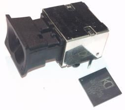
Figure 2: Schematic for a 1 Gbps POF switch.

4. Performance

4.1. Link Budget and Sensitivity
Table 2 shows optical performance with three different fibers (Fiber 1 - GH4002, Fiber 2 - HMCKU1000PW and
Fiber 3 - MH4002) under different conditions. AOP stands for Average Optical Power.

    Home Networking                              25ºC                                  70ºC
     25 m @ 1 Gbps               Fiber 1        Fiber 2      Fiber 3      Fiber 1     Fiber 2     Fiber 3
AOP at TX (dBm)                      -3.15          -3.15        -3.15           -5          -5          -5
POF attenuation (dBo)                 -3.7           -5.7         -5.6         -3.7        -5.7        -5.6
RX lens coupling loss (dBo)              -2             -2           -2          -2          -2          -2
Sensitivity at PD (dBm)              -20.5          -20.7        -21.5        -20.2       -20.4       -21.2
Link budget (dBo)                    15.35          15.55        16.35         13.2        13.4        14.2
Link margin (dBo)                    11.65           9.85        10.75          9.5         7.7         8.6
Home Networking 25ºC 70ºC
50 m @ 1 Gbps Fiber 1 Fiber 2 Fiber 3 Fiber 1 Fiber 2 Fiber 3
AOP at TX (dBm) -3.15 -3.15 -3.15 -5 -5 -5
POF attenuation (dBo) -8.5 -9.6 -11.5 -8.5 -9.6 -11.5
RX lens coupling loss (dBo) -2 -2 -2 -2 -2 -2
Sensitivity at PD (dBm) -19 -19.6 -21 -18.7 -19.3 -20.7
Link budget (dBo) 13.85 14.45 15.85 11.7 12.3 13.7
Link margin (dBo) 5.35 4.85 4.35 3.2 2.7 2.2
Industrial (Long Reach) 25ºC 85ºC
50 m @ 100 Mbps Fiber 1 Fiber 2 Fiber 3 Fiber 1 Fiber 2 Fiber 3
AOP at TX (dBm) -3.15 -3.15 -3.15 -6 -6 -6
POF attenuation (dBo) -8.5 -9.6 -11.5 -8.5 -9.6 -11.5
RX lens coupling loss (dBo) -2 -2 -2 -2 -2 -2
Sensitivity at PD (dBm) -33 -33.1 -33.2 -32.6 -32.7 -32.8
Link budget (dBo) 27.85 27.95 28.05 24.6 24.7 24.8
Link margin (dBo) 19.35 18.35 16.55 16.1 15.1 13.3
Industrial (Long Reach) 25ºC 85ºC
100 m @ 100 Mbps Fiber 1 Fiber 2 Fiber 3 Fiber 1 Fiber 2 Fiber 3
AOP at TX (dBm) -3.15 -3.15 -3.15 -6 -6 -6
POF attenuation (dBo) -18.3 -18.1 -20.3 -18.3 -18.1 -20.3
RX lens coupling loss (dBo) -2 -2 -2 -2 -2 -2
Sensitivity at PD (dBm) -32.9 -32.8 -33.1 -32.5 -32.4 -32.7
Link budget (dBo) 27.75 27.65 27.95 24.5 24.4 24.7
Link margin (dBo) 9.45 9.55 7.65 6.2 6.3 4.4
Home Net ABR perfor-
mance at 25ºC (Mbps) 50 m 75 m 100 m
Fiber 1 - GH4002 1000 850 400 Fiber 1: GH4002
Fiber 2 - HMCKU1000PW 1000 850 550 Fiber 2: HMCKU1000PW
Fiber 3 - MH4002 1000 850 550 Fiber 3: MH4002
Table 2: Link budget, link margin and ABR performance with three commercial POF fibers under different
conditions.
4.2. Power supply and consumption
The power supply strategy has been implemented to balance power efficiency with board layout flexibility. The
ASSP can be single-supplied with a regulated 3.3V external source. Thanks to the internal regulators (see Figure 3),
the needed internal voltages are self-generated (1.2V and 2.5V).
If external power supplies are available, the ASSP can take advantage of the on-board sources and avoid internal
voltage generation with the benefit of higher power efficiency and lower dissipation.
Overall, depending on the supply scheme chosen by the board designer, power consumption could range between a
minimum of < 500 mW (no internal regulation) and a maximum of < 8 mW (single 3.3V supply).Figure 3: Internal voltage supply scheme in which all required voltages are generated internally from the single
3.3V supply.
5. Optical Transceiver
In combination with KDPOF’s KD1000 ASSP, the AVAGO Technologies analog POF transceiver provides the
system designer with the ability to implement Gigabit Ethernet over 2.2mm jacketed standard POF.
One of the main features of the analog POF transceiver is the possibility to connect POF cable using a simple insert
and lock system which eliminates the need for a connector. This enables a very fast installation and maintenance.
This compact transceiver is lead free and compliant with RoHS. The form factor is similar to the well-known RJ45
connector.
The analog POF transceiver package contains the two optical subassemblies, transmitter and receiver, which are
mounted in the housing for bare fiber connection. The metal shield provides excellent immunity to EMI/EMC.
The main features of KDPOF/AVAGO solution are:
Easy bare fiber termination solution for 2.2mm jacket POF
EMI/ EMC robust
Operating temperature range -40°C to 85°C
Single 3.3V power supply operation
Integrated optics to efficiently focus light for fiber coupling
Figure 4: Optical transceiver with Avago Technologies analog POF transceiver.
5.1. Transmitter
Two devices compose the transmitter: a linear current silicon driver and a 650nm fast LED. The driver linearly con-
verts a differential input voltage signal into current for proper LED operation. The driver implements a slow auto-
matic Extinction Ratio (ER) and current bias control by sensing the input voltage signal. This control loop ensures
the linear operation of the LED in the full range of temperature conditions without optical clipping.
The extinction ratio (ER) and bias control, together with advanced current pre-emphasis circuitry and highly linear
wide-band current steering, enable the optical transmitter for advanced linear modulations as required to achieve
reliable 1 Gbps over POF in combination with the KDPOF KD1000 ASSP.
The fast LED is the same device already qualified for automotive applications, thus leveraging the robustness re-
quired by the automotive market to Gigabit over POF applications.Under the control of KD1000, the transmitter can be set into a power-saving state effectively enabling a Low Power
Idle (LPI) mode as defined in VDE v 0885-763.
5.2. Receiver
The receiver part of the transceiver is a complete monolithically-integrated linear fiber optical receiver that compris-
es an integrated pin-photodiode with a diameter of 390 μm and the necessary amplifiers and logic. The circuit is
completely shielded against stray light and electromagnetic fields. This, along with its high sensitivity, makes it an
ideal choice for applications with over-illuminated receivers of large-core fiber transmission systems in harsh envi-
ronments. The receiver is manufactured in a silicon technology optimized for low-cost high-reliability fiber commu-
nication applications.
The receiver features a highly linear transimpedance amplifier for signals with a wide average optical input power
range of up to 0 dBm at a wavelength of 670 nm. An integrated automatic gain control circuit ensures optimal and
predictable behavior for modulation signals with high crest factors. At the highest transimpedance a bandwidth of 30
MHz is attained.
The optical receiver provides a monitoring current output, which represents the average optical power collected from
the photodiode. As in the case of the transmitter, the receiver can be set into a power-saving state by externally forc-
ing this output to a voltage above a threshold, effectively allowing the implementation of Low Power Idle (LPI)
modes.
6. Evaluation Kit
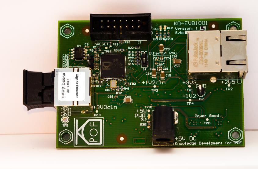
To enable customers to evaluate the KD1001 product, KDPOF has released the KD-EVK1001-MC Media Converter
Evaluation Kit. This kit is a tool to design and evaluate high-speed prototypes using the KD1001 Gigabit Ethernet
POF transceiver IC (10 mm x 10 mm, 88-pin QFN plastic package). The Evaluation Kit contains two KD-EVB1001-
MC media-converter boards, which interface the free graphical user interface (GUI) tool from KDPOF for
PC/MAC/Linux platforms. This flexible and self-contained kit enables easy monitoring and configuration, easy eval-
uation of performance and real time monitoring.
Figure 5: KD-EVB1001-MC media converter board. The Media Converter Evaluation Kit contains two boards to
configure a point-to-point link to evaluate the performance of the KD1001 ASSP.
As shown in Figure 6, the kit allows the installation of a test set-up configured as a point-to-point POF link using two
media-converter boards. A single computer can be used to monitor low-level parameters of the link. The connection
between the computer and the boards is made using the supplied USB2All box. The kit is easy to use with common
lab equipment, without need for additional items. A GUI tool eliminates need for additional BER equipment. This kit
enables real-time monitoring of the link, and reporting key performance parameters like: distortion, frequency and
time channel response, MLCC constellations, PHY and net rates, SNR at decoding, received average optical power
and BER after FEC. Status of the KD1001 is accessed through the GUI, which is run on a computer connected via
USB.Figure 6: Typical test set-up using the components of the kit.
The GUI, shown in Figure 7, includes several panels, which provide complete access to the KD1001 transceiver, link
status and parameters. The GUI also includes a BER panel to capture bit error rate at the receiver.
0
Figure 7: GUI tool which provides reported PHY information in real time.
References
[1] C. Pardo, O.Ciordia, R. Pérez de Aranda, “KD-PHY1000 IC Family: The First Gigabit POF Standard
Implementation”, in Proceedings of 2012 POF Conference. Atlanta, Georgia.
[2] P. Reviriego, R. Pérez de Aranda, C. Pardo, “Introducing Energy Efficiency in the VDE v 0885-763 Standard
for High Speed Communications over Plastic Optical Fibres” IEEE Communications Magazine. August 2013.
[3] G. D. Forney et al., "Sphere-bound-achieving coset codes and multilevel coset codes", IEEE Trans. on
Information Theory, vol. 46, no. 3, May 2000, pp. 820-850.
[4] M. Tomlinson, "New Automatic Equaliser Employing modulo Arithmetic", IET Electron. Letters, vol. 7, no. 5,
Mar. 1971, pp. 138-39.
[5] H. Harashima and H. Miyakawa, "Matched-Transmission Technique for Channels with Intersymbol
Intereference", IEEE Trans. Commun., vol. 20, no. 4, Aug. 1972, pp. 774-80.You can also read