VK-1 Viking Synthesizer - 1.0.2 User Manual - Blamsoft
←
→
Page content transcription
If your browser does not render page correctly, please read the page content below
VK-1 Viking Synthesizer

1.0.2 User Manual
2
Overview
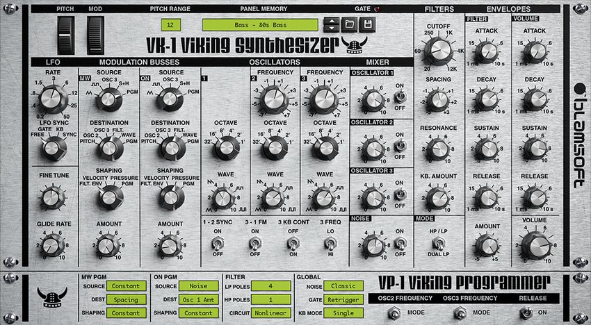
VK-1 is an emulation of a famous monophonic analog synthesizer. It has three continuously
variable wave oscillators, two ladder filters with a Dual Lowpass or Highpass/Lowpass
configuration, a multi-wave LFO, and two modulation busses. VK-1 uses state of the art DSP
technology to accurately reproduce the sound of the hardware.
Quick Start
Using your favorite VST host, select VK-1 Viking Synthesizer under manufacturer Blamsoft.
Click on the patch display or use the up and down arrows to browse the factory presets. Try
turning knobs. Use shift+drag to precisely control a knob. Use ctrl/cmd click to reset a knob.
Presets
VK-1 comes with presets in the categories Bass, Bright Lead, Electro Bass, FX (Effects), Perc
Lead (Percussive Lead), Soft Lead, and Synthwave. These categories are well suited to a
monophonic instrument like VK-1 that excels at bass and lead sounds. The 100 Electro Bass
and Synthwave presets were designed by renowned sound designer eXode. To reset VK-1 to
default settings, load the Default preset.
Click on the patch name to load a factory preset. Use the arrow buttons or keyboard arrow
keys to change presets. Use the open button to load a repatch (RE compatible) preset.
Patches load immediately when clicked and you can use the arrow keys in the file browser.
© 2017 Blamsoft, Inc. All rights reserved.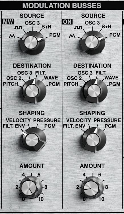
3
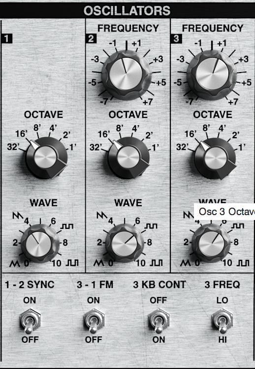
Oscillators
VK-1 has three continuously variable wave oscillators with a few extra settings to tweak how
they operate.
Octave
The Octave knob sets the octave of the oscillator. Note that the octave labeled 4’ directly
matches the keyboard pitch.
Frequency
The Frequency knob adjusts the pitch of the oscillator. The knob adjusts the pitch in the range
of -7 to +7 semitones away from the true pitch. Note that there are switches that affect the
behavior of this knob. When Fine mode is enabled, the knob adjusts the pitch in the range of -
0.7 to +0.7 semitones. The fine adjustments are useful for subtly fattening the sound of a
patch. Semi mode locks the frequency to semitones.
© 2017 Blamsoft, Inc. All rights reserved.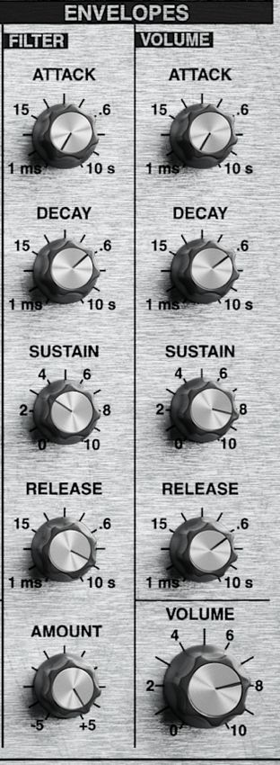
4

   Wave
   The Wave knob adjusts the waveform of the oscillator. The waveform changes from triangle to
   saw to square to pulse as the knob is swept from left to right. A triangle is useful as a mellow
   sound, a saw as a bright and buzzy sound, a square as a hollow digital sound, and a pulse as
   a thin grainy sound. Since the knob is continuously variable, the in-between settings offer
   many possibilities.

   1-2 Sync
   The 1-2 Sync switch locks oscillator 2 to the frequency of oscillator 1. This is done by resetting
   oscillator 2 to the beginning of its waveform whenever oscillator 1 repeats its waveform.

Oscillator 2

Oscillator 1

   3-1 FM
   The 3-1 FM switch hooks the output of oscillator 3 into the frequency control input of oscillator
   1. Both the waveform and frequency of oscillator 3 can greatly affect the resulting sound.

   3 KB Off
   The Oscillator 3 Keyboard Off switch selects whether or not the keyboard controls the pitch of
   Oscillator 3. Normally Oscillator 3 tracks the keyboard. When it is enabled, Oscillator 3 is a
   C#3 pitch.

                               © 2017 Blamsoft, Inc. All rights reserved.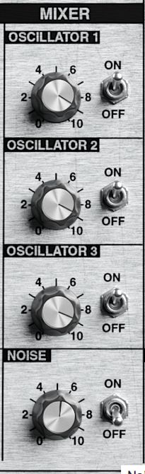
5

3 Freq Lo
The Oscillator 3 Low Frequency switch selects whether Oscillator 3 is high or low frequency.
When it is off, octave 4’ matches the keyboard notes as usual. When it is enabled, the pitch of
Oscillator 3 is six octaves below what it would be in the high frequency setting.

Mixer
The Mixer page is used to adjust the volume of the oscillators and noise. The mixer sources
are summed and fed to the filters.

Oscillators
The switches enable the audio of each oscillator and the knobs adjust their level.

Noise
The switch turns on the audio from the noise source and the knob adjusts its level.

Note that the oscillators and noise are always available as modulation sources. These switches
and knobs control the audio mix.

                           © 2017 Blamsoft, Inc. All rights reserved.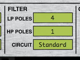
6

Filters
VK-1 has dual filters modeled after the classic transistor ladder filter. In Dual Lowpass mode,
the filters are in parallel in the left and right output channels. In HP/LP mode the filters are in
series, one highpass and one lowpass. The number of poles is adjustable from 1 to 4. More
poles create a steeper slope and a sharper cutoff.

Cutoff
The cutoff frequency is known by many names. It is called the 3dB point, transition point, or
knee of the filter. It is where the pass-band ends and the slope begins. In a lowpass filter the
response slopes down at 6 dB per octave per pole above this frequency. You can consider
frequencies above this frequency to be mostly rejected or “filtered out” by the filter. And in

                            © 2017 Blamsoft, Inc. All rights reserved.
7

VK-1’s band-pass filter (HP/LP), the cutoff is at the high end of the pass-band, see Spacing for
more detail.

Spacing
Spacing is where the two filters come into play. Spacing adjusts the frequency difference, in
octaves, between the two filters. In Dual Lowpass mode, one filter is heard in the left channel
and the other in the right. Spacing adjusts the cutoff frequency of the left filter with respect to
the right.

In Highpass/Lowpass mode, Spacing also adjusts the difference in octaves. But in this case the
two filters are in mono, and spacing adjusts the highpass filter with respect to the lowpass. The
highpass filter is one octave below the lowpass when the knob is fully turned to the right, and
decreases in frequency as the knob is turned to the left. So, turning the knob to the left widens
the pass band.

Resonance
The resonance knob adjusts the gain of positive feedback from the output of the filter to the
input. It creates a peak in the filter response at the cutoff frequency. Frequencies near the
resonance are amplified resulting in a ringing sound.

KB Amount
Keyboard Amount controls the tracking of the filter with respect to the keyboard notes. When
Keyboard Amount is set to zero, the filter cutoff frequency does not depend on the note
being played. When Keyboard Amount is all the way up, the filter cutoff frequency moves one
semitone per key and exactly tracks the keyboard.

Mode
Mode selects whether the filter is Dual Lowpass, one filter in the left channel and the other in
the right, or Highpass/Lowpass, a bandpass filter created by a highpass and lowpass in series.

                            © 2017 Blamsoft, Inc. All rights reserved.
8

Circuit
The Circuit setting chooses between various DSP algorithms. All of the algorithms are Zero
Delay Feedback. The HQ mode uses a higher quality algorithm with a Newton solver. The
algorithms have been tuned to simulate the frequency response and resonant behavior of an
analog transistor ladder filter.

The Drive settings use the Standard algorithm with increased input gain to create distortion.
Drive I, II, and III progressively provide more gain into the filter causing it to saturate and add
a gritty overdrive timbre.

Poles
The number of poles sets the steepness of the filter frequency response. Each pole results in 6
dB per octave slope. Fewer poles result in a less filtered sound.
   •    1 pole – 6 dB per octave
   •    2 poles – 12 dB per octave
   •    3 poles – 18 dB per octave
   •    4 poles – 24 dB per octave

                             © 2017 Blamsoft, Inc. All rights reserved.
9
Frequency Response
This image shows the frequency response of VK-1’s 24 dB per octave lowpass filter. The low
frequencies have a flat response and frequencies past the cutoff point are attenuated. When
fewer the 4 poles are used, the slope is not as steep.
Gain
Frequency
© 2017 Blamsoft, Inc. All rights reserved.10
Now the resonance knob has been turned up. Notice the peak at the cutoff frequency.
Gain
Frequency
When in Highpass/Lowpass mode, one of the filters is a highpass filter. The two filters are
connected in series to create a bandpass filter. Note that the lowpass filter is always the
resonant filter. The highpass filter does not resonate.
© 2017 Blamsoft, Inc. All rights reserved.11
Envelopes
The envelopes control the filtering and volume of the sound to create movement
within a note. The filter envelope controls the filter cutoff frequency. The volume
envelope controls the output amplitude of the sound.
Attack
Attack is a measurement of the time it takes the envelope to go from zero to full amount in
the initial phase. The attack time ranges from 1 millisecond to 10 seconds.
Decay
Decay is a measurement of the time it takes the envelope to go from the maximum to the
sustain level in the second phase. The decay time ranges from 1 millisecond to 10 seconds.
© 2017 Blamsoft, Inc. All rights reserved.12
Sustain
Sustain is an amplitude measurement. It is the settling amplitude of the third phase of the
envelope, while a key is held.
Release
Release is a measurement of the time it takes the envelope to go from the sustain level back
to zero when a key is released.
When a key is press the first three phases occur. When the key is released the Release phase
occurs.
Sustain Attack Decay Release
Amount
The Amount knob controls how the filter cutoff is affected by the filter envelope. When it is set
to zero the envelope has no effect on the cutoff. When it is set to +5 the filter cutoff will move
seven octaves above its original value at the envelope maximum. When it is set to -5 it will
move a maximum of seven octaves below its original value.
© 2017 Blamsoft, Inc. All rights reserved.13
Modulation
LFO
The LFO is a low frequency oscillator used for modulation. Its output is a triangle wave, a
square wave, and sample and hold.
Triangle
Square
S+H
Note that the triangle wave is positive and negative, while the square wave is only zero and
positive. The sample and hold signal is positive and negative. The Sample and Hold signal gets
its name because an input is sampled and then that value is held during one period of the
LFO. In this case the input is noise, so the held value is random.
© 2017 Blamsoft, Inc. All rights reserved.14
Sync
LFO Sync can be used to optionally reset the LFO or lock the LFO to the song tempo. When
Free is selected the LFO is not locked to the tempo. When Gate is selected, the LFO waveform
resets to the beginning of a period whenever the gate opens. This occurs when a key is
pressed without another one held. When Keyboard is selected, the LFO waveform resets any
time a key is pressed. Sync locks the LFO to the current tempo and changes the meaning of
the Rate knob to beat divisions.
Rate
The Rate knob controls the rate of the LFO. In the free running modes, the frequency ranges
from 0.2 Hz to 50 Hz. In synced mode, rhythmic divisions of the current tempo are available.
Modulation Busses
© 2017 Blamsoft, Inc. All rights reserved.15
The Modulation Busses allow you to route signals that can subtly or drastically impact aspects
of the sound depending on how much or what is modulated. They allow for much more
complex sounds than can be achieved with the oscillators and filters by themselves.
There are two modulation busses, Mod Wheel, and On. The Mod Wheel bus has its final
amount controlled by the Mod Wheel in addition to the Amount knob. The On bus is always
on; its amount is set with the Amount knob.
Note that there are settings in the programmer below. These settings come into play when
PGM is selected above.
Source
The busses can be thought of as electrical busses, or simply connections to a common circuit.
The Source selects the input to be connected to the bus. The source can be one of several
options described in the table.
Triangle LFO triangle waveform
Square LFO square waveform
Osc 3 Oscillator 3
S+H LFO sample and hold waveform
Off Zero
Constant, -Constant A steady value
Noise A noise source
Filt Env The filter envelope
-Filt Env Zero minus the filter envelope, or the
envelope negated
S - Filt Env The filter sustain amount minus the filter
envelope. This results in a positive value
© 2017 Blamsoft, Inc. All rights reserved.16
initially, going to a zero value during the
sustain phase, then back positive
Filt Env - S The filter envelope minus the filter sustain
amount. This results in a negative value
initially, going to a zero value during the
sustain phase, then back negative
Vol Env The volume envelope
-Volume Env Zero minus the volume envelope, or the
volume negated
S - Vol Env The volume sustain amount minus the
volume envelope. This results in a positive
value initially, going to a zero value during
the sustain phase, then back positive
Vol Env – S The volume envelope minus the volume
sustain amount. This results in a negative
value initially, going to a zero value during
the sustain phase, then back negative
S+H Filt The LFO sample and hold waveform
smoothed by a filter
Osc 1 Oscillator 1
Osc 2 Oscillator 2
Destination
The Destination connects the bus to a control input of another part of the synth. It effectively
connects the source to the destination. The destination can be one of several options
described in the table.
Pitch Affects the pitch of all three oscillators
Osc 2 Affects only the pitch of Oscillator 2
Osc 3 Affects only the pitch of Oscillator 3
Filt Filter Cutoff
© 2017 Blamsoft, Inc. All rights reserved.17
Wave Controls all three oscillator wave-shapers
concurrently
Constant, -Constant A steady value
Noise A noise source
LFO Rate LFO Frequency
Resonance Filter Resonance Amount
Spacing Filter Spacing
Pan Output panning
Osc 1 Amt Oscillator 1 volume level
Osc 2 Amt Oscillator 2 volume level
Osc 3 Amt Oscillator 3 volume level
Noise Amt Noise volume level
Master Vol Master volume level
Shaping
Shaping can be used to increase the effect of the source on the destination, increasing the
amount of modulation. Shaping values are in a positive range, zero or more. As the Shaping
parameter increases the effect of the source increases. For example, if the shaping is set to
Pressure, lightly holding down a key will result in the typical amount of modulation. But
pushing the key down harder will increase the modulation. The shaping setting can be one of
several options described in the table.
Filt Env Filter Envelope
Velocity MIDI velocity of the current note
Pressure MIDI aftertouch
Off No shaping
Constant A steady value
PW Pitch Wheel
MW Mod Wheel
© 2017 Blamsoft, Inc. All rights reserved.18
Note MIDI Note
MW Bus The other modulation bus
On Bus The other modulation bus
Other All of the other shaping values are simply
knob settings with the same name.
Common Tricks
One common trick is to use filter envelope (Filt Env) shaping with the filter envelope (Filt Env)
as the source and the filter (Filt) as the destination. This technique can greatly increase the
filter cutoff movement.
Another trick is to use velocity to control the filter cutoff. For this you can use Constant as the
Source, filter cutoff (Filt) as the Destination, and Velocity as the Shaping. In general, when you
want to use the shaping as an effect you may want to choose Constant as the Source.
Global
There are miscellaneous other settings that affect operation of the synth.
© 2017 Blamsoft, Inc. All rights reserved.19
Fine Tune
Fine Tune adjusts the overall tuning, including all three oscillators. Generally, it would be used
to transpose the instrument or adjust the pitch of the oscillators simultaneously. It is the only
way to adjust the pitch of Oscillator 1.
Glide Rate
Glide Rate, also known as portamento, adjusts how quickly the oscillator pitch changes to a
new note. Turning the Glide Rate up makes the pitch transition smooth between notes.
Glide On
Glide On is a hidden parameter that can be accessed through the host’s automation. You can
enable and disable glide with this setting.
Drift
Drift is a hidden parameter that can be accessed through the host’s automation. Drift
simulates the instability oscillators have in their frequency. Even when the tuning trim pots
have been set very accurately the oscillator frequency of an analog oscillator drifts slightly up
and down. Slight phase shifts result from the slightly out of tune oscillators. Turning this
control down will fix the frequency at an exact rate. Turning it up magnifies the effect.
KB Stretch
Keyboard Stretch is a hidden parameter that can be accessed through the host’s automations.
It adjusts the tuning of the keyboard notes. Normally, each key is one semitone apart. Analog
keyboards often go out of tune, and the keyboard spacing is no longer one semitone. The
note spacing can be adjusted from 0.98 semitones to 1.02 semitones. C5 is at the center while
the rest of the notes become detuned. If you don’t want C5 to be in tune you can adjust the
Fine Tune or the oscillator frequency controls.
© 2017 Blamsoft, Inc. All rights reserved.20
Pitch Bend Range
The Bend Range knob sets the maximum number of semitones that the Pitch Wheel
can adjust the oscillator pitch.
Noise
Choose classic for an old school sound, White for the typical noise, or Pink for another type of
noise commonly used in audio.
Gate
This setting can be used to hold the gate open or set the retrigger mode. The gate controls
when the envelopes reset based on a new note.
• Legato – Envelopes are only triggered if no keys are held
• On - Like always holding down a key
• Retrigger – Envelopes are triggered with every key
Keyboard Mode
Various monophonic keyboard settings are available to choose from:
• Last – The last key pressed sets the pitch.
• Lowest – The lowest key pressed sets the pitch
• Highest – The highest key pressed sets the pitch
• Single – A key will set the pitch as long as it is held regardless of other key presses
© 2017 Blamsoft, Inc. All rights reserved.21
Release On
You can enable and disable release with this switch.
Volume
If you have never seen a volume knob before, you will mostly likely have a very hard time
using this synth. But don’t give up. The Volume knob is the last stage of the synth. It controls
the overall volume after mixing and enveloping has occurred.
MIDI Learn
Some hosts use MIDI to communicate with the VST (note: Reason does not use MIDI). You can
setup controls in VK-1 to respond to your MIDI controller. Right-click on the VK-1 knob or LCD
and choose MIDI Learn. Then turn the knob on your MIDI controller. To forget the mapping,
choose MIDI Forget. Note, only one VK-1 control can be mapped to a CC.
© 2017 Blamsoft, Inc. All rights reserved.22
Contact
Click to connect with Blamsoft on social media.
Or visit our website:
© 2017 Blamsoft, Inc. All rights reserved.You can also read