WGR MAGNUM SERIES CONTROLLED ROTATION SEWER NOZZLE AND SWITCHER HEAD USER MANUAL - StoneAge Waterblast Tools
←
→
Page content transcription
If your browser does not render page correctly, please read the page content below
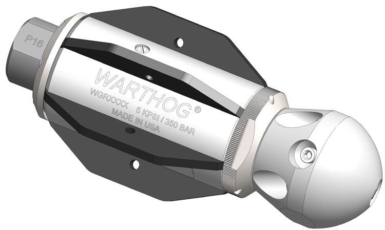
WGR MAGNUM SERIES
  CONTROLLED ROTATION
         SEWER NOZZLE
    AND SWITCHER HEAD
          USER MANUAL

                 PL 533 REV I
                    (07/2021)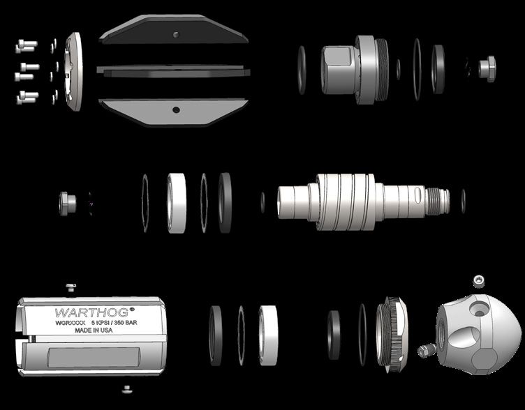
TABLE OF CONTENTS

    .MANUFACTURER’S INFORMATION. . . . . . . . . . . . . . . . . . . . . . . . . . . . . . . . . . . . . . . . . . . . . . . . . . . . . . . . . . . . 3

             SPECIFICATIONS. . . . . . . . . . . . . . . . . . . . . . . . . . . . . . . . . . . . . . . . . . . . . . . . . . . . . . . . . . . . . . . . . . . . . . . . . . 3
             DESCRIPTION AND INTENDED USE. . . . . . . . . . . . . . . . . . . . . . . . . . . . . . . . . . . . . . . . . . . . . . . . . . . . . . . 3
             KEY FEATURES. . . . . . . . . . . . . . . . . . . . . . . . . . . . . . . . . . . . . . . . . . . . . . . . . . . . . . . . . . . . . . . . . . . . . . . . . . . . 3

    TOOL OVERVIEW. . . . . . . . . . . . . . . . . . . . . . . . . . . . . . . . . . . . . . . . . . . . . . . . . . . . . . . . . . . . . . . . . . . . . . . . . . . . . . . 4
             WGR MODELS AND HEAD SPECIFICATION INFORMATION. . . . . . . . . . . . . . . . . . . . . . . . . . . . . . . 4
             TOOL WEIGHTS AND DIMENSIONS. . . . . . . . . . . . . . . . . . . . . . . . . . . . . . . . . . . . . . . . . . . . . . . . . . . . . . . 5

    WARNING AND SAFETY INSTRUCTIONS. . . . . . . . . . . . . . . . . . . . . . . . . . . . . . . . . . . . . . . . . . . . . . . . . . . . . . 6

    OPERATION. . . . . . . . . . . . . . . . . . . . . . . . . . . . . . . . . . . . . . . . . . . . . . . . . . . . . . . . . . . . . . . . . . . . . . . . . . . . . . . . . . . . . 8

    TROUBLESHOOTING. . . . . . . . . . . . . . . . . . . . . . . . . . . . . . . . . . . . . . . . . . . . . . . . . . . . . . . . . . . . . . . . . . . . . . . . . . . 9

    FLUID REPLACEMENT.. . . . . . . . . . . . . . . . . . . . . . . . . . . . . . . . . . . . . . . . . . . . . . . . . . . . . . . . . . . . . . . . . . . . . . . . . 10

    WGR MAGNUM MAINTENANCE TOOLS AND MATERIALS. . . . . . . . . . . . . . . . . . . . . . . . . . . . . . . . . . . . 11

    DISASSEMBLY. . . . . . . . . . . . . . . . . . . . . . . . . . . . . . . . . . . . . . . . . . . . . . . . . . . . . . . . . . . . . . . . . . . . . . . . . . . . . . . . . . 12

    ASSEMBLY. . . . . . . . . . . . . . . . . . . . . . . . . . . . . . . . . . . . . . . . . . . . . . . . . . . . . . . . . . . . . . . . . . . . . . . . . . . . . . . . . . . . . . 16

    WGR SWITCHER 1 AND 1¼ . . . . . . . . . . . . . . . . . . . . . . . . . . . . . . . . . . . . . . . . . . . . . . . . . . . . . . . . . . . . . . . . . . . . 21

             OVERVIEW. . . . . . . . . . . . . . . . . . . . . . . . . . . . . . . . . . . . . . . . . . . . . . . . . . . . . . . . . . . . . . . . . . . . . . . . . . . . . . . . . 21
             WGR SWITCHER MAINTENANCE TOOLS AND MATERIALS.. . . . . . . . . . . . . . . . . . . . . . . . . . . . . . 21
             OPERATION AND TROUBLESHOOTING.. . . . . . . . . . . . . . . . . . . . . . . . . . . . . . . . . . . . . . . . . . . . . . . . . . . 22
             WGR SWITCHER DISASSEMBLY. . . . . . . . . . . . . . . . . . . . . . . . . . . . . . . . . . . . . . . . . . . . . . . . . . . . . . . . . . 23
             WGR SWITCHER ASSEMBLY. . . . . . . . . . . . . . . . . . . . . . . . . . . . . . . . . . . . . . . . . . . . . . . . . . . . . . . . . . . . . . 24

    WGR AND SWITCHER MAINTENANCE SCHEDULE.. . . . . . . . . . . . . . . . . . . . . . . . . . . . . . . . . . . . . . . . . . . 25

    PART NAMES/NUMBERS AND SERVICE KITS. . . . . . . . . . . . . . . . . . . . . . . . . . . . . . . . . . . . . . . . . . . . . . . . . 26

    TERMS AND CONDITIONS AND WARRANTY. . . . . . . . . . . . . . . . . . . . . . . . . . . . . . . . . . . . . . . . . . . . . . . . . . 28

2                                                                               866-795-1586 • WWW.SEWERNOZZLES.COM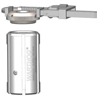
MANUFACTURER’S INFORMATION

StoneAge Inc.                                               StoneAge NL
466 S. Skylane Drive                                        Reedijk 7Q
Durango, CO 81303, USA                                      3274 KE Heinenoord
Phone: 970-259-2869                                         Netherlands
Toll Free: 866-795-1586                                     (+31) (0) 85 902 73 70
www.stoneagetools.com                                       sales-NL@stoneagetools.com
This manual must be used in accordance with all applicable national laws. The manual shall be
regarded as a part of the machine and shall be kept for reference until the final dismantling of the
machine, as defined by applicable national law(s).
                                 Updated manuals can be downloaded at:
                              https://www.warthog-nozzles.com/resources/

           SPECIFICATIONS
                   Tool Family:                            Warthog Magnum
                   Tool Model:                   WGR-1                          WGR-1-1/4
                          Units:     Imperial            Metric           Imperial        Metric
                     Pipe Size:       8-36 in.      203-914 mm            8-36 in.     203-914 mm
             Pressure Range: 1200-5000 psi           83-345 bar       1200-5000 psi     83-345 bar
                  Flow Range:       50-80 gpm       189-303 lpm        80-120 gpm      303-454 lpm
            Outside Diameter:         4.5 in.            114 mm           5.75 in.       146 mm
                Overall Length:      10.25 in.           260 mm           10.25 in.      260 mm
                       Weight:       13.25 lbs            6 kg            13.55 lbs       6.1 kg
              Rotation Speed:              150-400rpm                           150-300rpm
             Inlet Connection:           1” NPT or BSPP                     1 1/4” NPT or BSPP
                 Nozzle Ports:             7 x 1/8” NPT                         7 x 1/8” NPT
                  Flow Rating:                                     6 Cv
                 Pulling Force:    Reference http://jetting.stoneagetools.com/#/t/sw for values

DESCRIPTION OF EQUIPMENT AND INTENDED USE                         KEY FEATURES:
                                                                  • Optimized speed control extends mainte-
The WGR Warthog Magnum is the first tool in the
                                                                    nance intervals
Warthog Magnum Series, a line of sewer nozzles
                                                                  • Streamlined design prevents tool from
specifically designed for extended tool life, increased
                                                                    catching inside of pipe.
maintenance intervals and optimal handling of dirty or
recycled water.                                                   • Replaceable fins made of hardened steel
                                                                    for longer life available in different sizes.
                                                                  • Flush style head protects front shaft seals
                                                                    for extended fluid life.
                                                                  • Easily convertible from pulling to desca-
                                                                    ling
                                                                  • Descaling ports now come standard.
                                                                  • Latest seal technology effectively handles
                                                                    dirty or recycled water for improved
                                                                    performance
                                                                  • Choose your rotation speed with 3 viscous
                                                                    fluid options.

             866-795-1586 • WWW.SEWERNOZZLES.COM                                                                3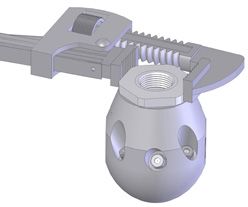
WGR MODELS AND HEAD SPECIFICATION INFORMATION

TOOL CONFIGURATION
Warthog sewer nozzles come in standard, descaling, and pulling configurations.
Standard nozzles utilize controlled rotation technology and a balanced jetting configuration to
deliver superior results in nearly all applications. We also offer nozzles that tune descaling or pulling
performance for a variety of special conditions.

See the illustration below for the relationship between jet angle and performance characteristics.

                                                                                                   Descaling

                          100°-135°       135°-150°     150°-180°                 Heavy Calcium
                                                                                 Deposits/Scaling

                                                                                    Light sidewall
                                                                                          build-up

    0°-15°

                                                                                   Sand & Sludge

                                                                                                     Pulling

                                      DESCALING MODE PULLING MODE
                   Choose the WGR configuration below that meets the needs of your job,
                              based on descaling power, more pulling power

                                                WGR TOOL LINE

                         Standard         NEW Root                  Puller
                         Descaler         Destroyer   Standard      Descaler             Puller

             DESCALING                                                                            PULLING

                              DESCALING      NEW WGR                PULLING
                              MODE           Control Clean            MODE

                              DESCALING                                        PULLING
                              MODE                     WGR Switcher              MODE

4                                                 866-795-1586 • WWW.SEWERNOZZLES.COM
TOOL WEIGHTS AND DIMENSIONS
DESCRIPTION:
The Magnum Series Warthog WGR (hereafter WGR) Controlled Rotation Sewer Nozzle is designed for
waterjet cleaning of pipes and sewer lines.
• Jet thrust from the water powers the rotation of the head and
pulls the tool through the line.
Front Jet
• The WGR is available with one of four female threaded inlet
nuts; 1” NPT, 1 1/4” NPT, 1”BSPP, or 1 1/4” BSPP
• The WGR-1 is capable of working pressures up to 5000 psi
and flow rates of 50 to 80 gpm. Side
Jets
• The WGR-1 1/4 is capable of working pressures up to 5000 psi
and flow rates of 80 to 120 gpm.
• The carbide high pressure seals allow the use of recycled
water or fresh water for jetting.
• The nozzle utilizes a rotor and viscous fluid speed control
mechanism to provide consistent rotation speed.
• As with all Warthog nozzles, the orifice sizes are selected to
best match the desired operating conditions of pressure and
flow.
• Hose length and size must be known to correctly determine
the proper orifice sizes. Back Jets
• Contact your distributor or reference
https://www.warthog-nozzles.com/ to help in nozzle selection.
STANDARD DESCALING HEAD OPTIONS
PRESSURE FLOW 1/8” NPT NOZZLE PORTS
MODEL/ HEAD TYPE
INLET FRONT SIDE BACK JET TYPE/
CONNECTION psi bar gpm lpm JET ∡ JET ∡ JET ∡ PORT PLUG
60-80 227-303 WGR 040-R20-SDS
WGR-1 4 @ 142o
1200- 83- CNP2/
50-70 189-265 WGR 040-R31-SDS 1 @ 15o 2 @ 100o
5000 345 GP 025-P2SS
WGR-1¼ 80-120 303-454 WGR 042-R20-SDS 6 @ 145o
ROOT DESTROYER HEAD
PRESSURE FLOW 1/8” NPT NOZZLE PORTS
MODEL/ HEAD TYPE
INLET FRONT SIDE BACK JET TYPE/
CONNECTION psi bar gpm lpm JET ∡ JET ∡ JET ∡ PORT PLUG
1200- 83- CNP2/
WGR-1-RD 50-80 189-303 WGR 042-R35-RD 1 @ 15o N/A 8 @ 135o
5000 345 GP 025-P2SS
PULLER HEAD
PRESSURE FLOW 1/8” NPT NOZZLE PORTS
MODEL/ HEAD TYPE
INLET FRONT SIDE BACK JET TYPE/
CONNECTION psi bar gpm lpm JET ∡ JET ∡ JET ∡ PORT PLUG
1200- 83- CNP2/
WGRP-1 50-80 189-303 WGR 040-R31-PDS 1 @ 15o 2 @ 100o 4 @ 155o
5000 345 GP 025-P2SS
SWITCHER HEAD OPTIONS PULLING / FLUSHING MODE CLEANING MODE
PRESSURE FLOW 1/8” NPT NOZZLE PORTS
MODEL/
INLET HEAD TYPE
CONNECTION FRONT SIDE BACK JET TYPE/
psi bar gpm lpm JET ∡ JET ∡ JET ∡ PORT PLUG
WGR-1-SWT 50-80 189-303 WGR 040-R31-SWT 4 @ 155o
1200- 83- 2 @ 100o CNP2/
1 @ 15o
5000 345 2 @ 125o GP 025-P2SS
WGR-1-CC 50-80 189-303 WGR 040-R45-CC 4 @ 135o
866-795-1586 • WWW.SEWERNOZZLES.COM 5WARNING AND SAFETY INSTRUCTIONS
OPERATOR TRAINING Operators MUST read, understand, and follow the
Operational and Training Requirements (Section
Managers, Supervisors, and Operators MUST be
7.0) of WJTA-IMCA’s Recommended Practices For
trained in Health and Safety Awareness of High-
The Use Of High-pressure Waterjetting Equipment,
pressure Water Jetting and hold a copy the Water
or equivalent.
Jetting Association (WJA) Code of Practice, or
equivalent (see www.waterjetting.org.uk). Operators MUST read, understand and follow
the Warnings, Safety Information, Assembly,
Operators MUST be trained to identify and
Installation, Connection, Operation, Transport,
understand all applicable standards for the
Handling, Storage, and Maintenance Instructions
equipment supplied. Operators should be trained
detailed in this manual.
in manual handling techniques to prevent bodily
injury.
StoneAge has designed and manufactured this The risk assessment MUST consider potential
equipment considering all hazards associated material or substance hazards including:
with its operation. StoneAge assessed these risks
• Aerosols
and incorporated safety features in the design.
• Biological and microbiological (viral or
StoneAge WILL NOT accept responsibility for the
bacterial) agents
results of misuse.
• Combustible materials
IT IS THE RESPONSIBILITY OF THE INSTALLER/ • Dusts
OPERATOR to conduct a job specific risk • Explosion
assessment prior to use. Job specific risk • Fibers
assessment MUST be repeated for each different • Flammable substances
set up, material, and location. • Fluids
• Fumes
The risk assessment MUST conform to the Health
• Gases
and Safety at Work Act 1974 and other relevant
• Mists
Health and Safety legislation.
• Oxidizing Agents
PERSONAL PROTECTIVE EQUIPMENT PPE may include:
REQUIREMENTS
• Eye protection: Full face visor
Use of Personal Protective Equipment (PPE) is
• Foot protection: Kevlar® brand or steel toe
dependent on the working pressure of water and
capped, waterproof, non-slip safety boots
the cleaning application. Managers, Supervisors,
and Operators MUST carry out a job specific risk • Hand protection: Waterproof gloves
assessment to define the exact requirements for • Ear protection: Ear protection for a minimum
PPE. See Protective Equipment for Personnel of 85 dBA
(Section 6) of WJTA-IMCA’s Recommended
Practices For The Use Of High-pressure • Head protection: Hard hat that accepts a full
Waterjetting Equipment for additional information. face visor and ear protection
Hygiene - Operators are advised to wash • Body protection: Multi-layer waterproof
thoroughly after all waterjetting operations to clothing approved for waterjetting
remove any waterblast residue which may contain • Hose protection: Hose shroud
traces of harmful substances.
• Respiratory protection: May be required;
First aid provision - users MUST be provided with refer to job specific risk assessment
suitable first aid facilities at the operation site.
6 866-795-1586 • WWW.SEWERNOZZLES.COMWARNING AND SAFETY INSTRUCTIONS
WARNING PRE-RUN SAFETY CHECK
Operations with this equipment can be potentially Refer to WJTA-IMCA’s, Recommended Practices
hazardous. Caution MUST be exercised prior For The Use Of High-pressure Waterjetting
to and during equipment and water jet tool use. Equipment and/or The Water Jetting Association’s,
Please read and follow all of these instructions, WJA Code of Practice for additional safety
in addition to the guidelines in the WJTA information.
Recommended Practices handbook, available • Complete a job specific risk assessment and
online at www.wjta.org. Deviating from safety act on the resulting actions.
instructions and recommended practices can lead
• Adhere to all site specific safety procedures.
to severe injury and/or death.
• Ensure the waterblasting zone is properly
• Do not exceed the maximum operating
barricaded and that warning signs are posted.
pressure specified for any component in a
system. • Ensure the workplace is free of unnecessary
objects (e.g. loose parts, hoses, tools).
• The immediate work area MUST be marked
off to keep out untrained persons. • Ensure all Operators are using the correct
Personal Protective Equipment (PPE).
• Inspect the equipment for visible signs
of deterioration, damage, and improper • Check that the air hoses are properly
assembly. Do not operate if damaged, until connected and tight.
repaired.
• Check all hoses and accessories for damage
• Make sure all threaded connections are tight prior to use. Do not use damaged items. Only
and free of leaks. high quality hoses intended for waterblast
applications should be used as high-pressure
• Users of the Warthog® WGR MUST be
hoses.
trained and/or experienced in the use and
application of high-pressure technology • Check all high-pressure threaded connections
and cleaning, as well as all associated for tightness.
safety measures, according to the WJTA
• Operate the high-pressure water at full
Recommended Practices for the use of
pressure and use the Pneumatic Foot Pedal
High-pressure Waterjetting Equipment.
Dump Control to verify that the dump valve is
• Install mechanical stops, stingers and back working properly.
out preventers as appropriate when doing any
• Ensure that Operators never connect,
tube, pipe or vessel cleaning.
disconnect, or tighten hoses, adapters, or
• Always de-energize the system before accessories with the high-pressure water
servicing or replacing any parts. Failure to do pump unit running.
so can result in severe injury and/or death.
• Ensure no personnel are in the hydroblasting
zone.
866-795-1586 • WWW.SEWERNOZZLES.COM 7OPERATION
DANGER
Do not attempt to clean a manhole with the WGR hanging by the hose. The tool can turn around and
strike the Operator. Specific accessories are offered and are required to safely clean manholes. Do
not allow the tool to enter a manhole or vault while in operation. If the tool is not contained in a pipe it
presents a serious hazard and if not avoided could result in death or serious injury.
NOTE: A 15-25 foot long section of leader hose of a different color than the jetter hose is recommended
to indicate how close the tool is to exiting the pipe.
• Flush the jetter hose prior to installing the nozzle to remove debris. Install the hose guard or Tiger
Tail. If the WGR is being used in pipe diameters less than 10 inches it can be attached directly to
the hose end. If being used in larger pipes a straight rigid pipe or centralizer must be placed behind
the tool such that the rigid length is greater than the pipe diameter to ensure the tool cannot turn
around in the pipe.
• To clean lines, position the WGR and Tiger Tail so it can enter the pipe to be cleaned. The
recommended cleaning direction is upstream from the manhole.
• Slowly bring the pump up to pressure, making certain that the WGR begins to pull its way into the
pipe in the proper direction; allow it to advance a few feet and note the location of the leader hose
or other hose marker being used. Once the pump is up to operating pressure, feed out the reel at a
reasonable rate to allow the jets time to clean the pipe.
• If roots are present, feeding at a slower rate will improve the cleaning results. Depending on the
amount of debris in the pipe, it may be necessary to occasionally pull the WGR back toward the
manhole to prevent buildup of debris behind the tool.
• When finished cleaning, withdraw the tool back to its initial starting point noted by the location of
the leader or hose marker.
• Shut down and secure the pump before removing the WGR from the line.
• After the job has been completed, remove the WGR from the hose and blow out the water with
compressed air to prolong the life of the internal components.
Manhole
Tiger Tail
Nozzle
Water Flow Direction
Proper Nozzle Setup
8 866-795-1586 • WWW.SEWERNOZZLES.COMTROUBLESHOOTING
HEAD WILL NOT ROTATE:
• Check to see if any jets, or inserts, are plugged. Even if a jet is only partially blocked it can keep
the head from rotating. Jets must be removed from the head to be properly cleaned. Poking the
material plugging the jet back into the head will not fix the problem because it will re-plug the jet
once water starts flowing. If the jets are all clear, wash the nozzle off with water to remove any
debris or grit between the head, body and shaft. Then try rotating head by hand. It should feel free
with a slight amount of smooth resistance. If it feels rough, gritty, or hard to turn, the tool needs
to be repaired. It may need new bearings and shaft seals or seals. It is possible the tool needs
viscous fluid added or changed, but if viscous fluid is confirmed to be present, a rebuild should be
considered.
HEAD SPINS TOO FAST:
• If the nozzle is spinning significantly faster than normal, or if the nozzle starts to sound different
(like a jet engine or a turbo charger) the nozzle may be low on viscous fluid, or the viscous fluid
may be contaminated. In this case, add or change the fluid as appropriate. Continued operation
in this state can mechanically damage the tool and a rebuild may be required to replace the faulty
shaft seals.
HIGH-PRESSURE WATER SEALS LEAK:
• The WGR’s seal design uses a slight amount of water for lubrication. At full pressure it should
not leak more than a few drops with a new set of seals. The high pressure seals may need to be
replaced if you are not able to get to full pressure or when a continuous spray comes from under
the WGR Back Plate.
LOCK-UP TROUBLESHOOTING TIP:
• Rotate in reverse 1 1/4 to 1 1/2 turns to unlock braking mechanism. If tool rotates smoothly then
redress may not be required.
• If the head rotates freely by hand, check the jet sizes and calculate pressure loss through the coil
tubing and check with your distributor or StoneAge® to make certain there is enough jet torque to
provide rotation.
• Verify jetting at; http://jetting.stoneagetools.com/#/t/sw You may also contact your factory autho-
rized
Warthog® dealer or StoneAge®, Inc. for more information.
TO KEEP THE TOOL RUNNING AT ITS BEST, PLEASE FOLLOW THE
MAINTENANCE SCHEDULE IN THIS MANUAL
866-795-1586 • WWW.SEWERNOZZLES.COM 9FLUID REPLACEMENT
SPEED CONTROL FLUID CHANGE
The speed control fluid changing is made easy with the WGR and disassembly of the tool is not
required. This means there is less chance for contamination and longer overall tool life. Fluid changes
should only be performed by qualified persons.
This flushing procedure is only recommended for replacing the fluid with the same fluid.
Not all of the fluid will be replaced using this procedure, therefore full disassembly and cleaning of the
tool is recommended when changing to a different speed, or viscosity of fluid. The WGR is designed
for maximum viscous fluid life and frequent fluid changes should not be required. A full fluid change is
necessary when replacing bearings and shaft seals.
NOTICE
Improper fluid change maintenance can result in reduced bearing or shaft seal life. Use extreme care
when performing this procedure. The fluid is thick and only very light pressure should be applied to the
syringe. Excess pressure will force fluid past the inner shaft seals and into the bearings.
VISCOUS FLUID REPLACEMENT INSTRUCTIONS
1. Position the tool (preferably mounted in a
vise) at an angle with one Port Plug (BJ 026) REMOVE
at the highest point and the other Port Plug at TO FILL
the lowest point. Clean around, then remove
the upper Port Plug from the body.
BC 410
2. Fill the Syringe (BC 410) with viscous fluid by Syringe
removing the end near the handle, pulling out
the plunger, and pouring the Viscous Fluid
(BJ 048-x) in to fill the Syringe Body. With
plunger re-installed, purge air out of Syringe WGR
hose. Body
BJ 026
3. Screw the syringe into the upper port, then Upper
remove the lower Port Plug. Using the Port Plug
assistance of gravity, gently ease the new
fluid into the WGR Body while letting the old
fluid flow out the opposite hole.
4. Rotate the Head while flushing. BJ 026
DO NOT PRESSURIZE THE CHAMBER Lower
Port Plug
by aggressively forcing in fluid. The fluid is
thick and some time is required to complete WGR 040
the flush. Head
5. Reinstall the exit Port Plug, then remove the
Syringe and install the inlet Port Plug.
TECH TIP:
The rotation speed of the head can be fine tuned with three different viscous fluid choices to optimize
performance for specific applications;
Slow Fluid: BJ 048-S, Medium Fluid: BJ 048-M, Fast Fluid: BJ 048-F
The medium viscosity fluid is recommended by StoneAge for maximized performance and minimized
maintenance. Please contact your Dealer or StonAge Customer Service to select the right fluid for your
application.
10 866-795-1586 • WWW.SEWERNOZZLES.COMMAINTENANCE TOOLS AND MATERIALS
Product training and proper tools are required to service this nozzle. If you are uncomfortable
performing the service, bring the nozzle to your authorized dealer.
The use of a bench vise and an arbor press is recommended. Take care throughout the entire procedure
to keep the internals clean and free from grit, lint, and contamination. Failure to do so could result in
premature failure after service. See complete Disassembly and Assembly instructions in this manual.
For maintenance videos and more:
https://www.youtube.com/playlist?list=PL-XpY7HhmpxVkccu1zG45Wh5w0Vy3MwZ0
NECESSARY TOOLS: NECESSARY MATERIALS:
• 3/8” Drive Ratchet with 3” Extension • Clean lint free rags or blue shop towels
• Arbor Press (recommended) • Anti-Seize - Swagelok® Blue Goop®
• Bearing Splitter • StoneAge PN (GP 043)
• Bench vise (recommended) • Grease - Mobil Mobilux® EP1
• Cotton swab • StoneAge PN (GP 049)
• Large Adjustable Wrench • Loctite® Blue 242®
(12” Crescent® Wrench) • Isopropyl Alcohol
• Medium size flat-head screw driver • When installing jets, StoneAge uses
• Pic Parker® Yellow ThreadMate and Teflon
• Rubber Band Tape or an equivalent combination on
• Automotive Sliding Wrench the threads of each jet.
(18” Crescent® C718 Automotive Wrench)
• 5/32” Hex Key
WGR 612
TOOL KIT (INCLUDES)
WGR 180 WGR 181 WGR 182
Magnum Shaft Lock Pin Removal Press Tube Installation Press
WGR 183 WGR 184 WGR 186
Hex Tool Seal Press HP Seal Puller
SC 287 105
2½ Wrench
Mobil® and Mobilux® are registered trademarks and/or trademarks of Exxon Mobil®.
Loctite® and Threadlocker Blue 242® are registered trademarks of Henkel AG & Co. KGaA.
Blue Goop® is a registered trademark of Swagelok® Company
866-795-1586 • WWW.SEWERNOZZLES.COM 11DISASSEMBLY
DISASSEMBLY 2. Keep the flats of the Front Nut clamped
down in a bench vise with the Inlet Nut
1. Remove the Head by clamping it in a vise facing up for the next step.
with the Inlet Nut facing up. Push the
3. Wrap a rubber band around the fins to keep
provided Magnum Shaft Lock Pin through
them from falling out while removing the
the first hole in the Front Nut. Rotate the
back plate. Remove the six GS 319-0155
Body until the Shaft Lock Pin slides all the
Screws which attach the Back Plate with a
way through the Front Nut, locking the shaft
5/32” Hex Key. Once the Back Plate is off the
in place. Use an adjustable wrench or the
Fins can then be removed.
SC 287 105 (included in the WR 612 Kit) on
the flats of the Front Nut to loosen the body.
Unscrew the body from the head by hand.
5/32” Hex Key
(Not Included)
GS 519-02
Screws (6)
WGR 102 GW 319-F-T06
Inlet Nut Washers (6)
WGR 020 or 022
Back Plate
WGR 003
Body
SC 287 105
2½ Wrench
*Included in
WGR 612 KIT
WGR 180
WGR 101 Shaft
Shaft Lock Pin
WGR 081/ 082
Fins (6)
WGR 040-
CLAMP FLATS RXX-XXX
IN A VISE Head
WGR 004
Front Nut
CLAMP FLATS
IN A VISE
Figure 1: For Step 1 Figure 2: For Steps 2-3
12 866-795-1586 • WWW.SEWERNOZZLES.COMDISASSEMBLY
4. With the Body still in the vise, use an 7. Remove the Port Plug that is closest to the
Automotive Sliding Wrench on the flats of Front Nut with a medium size, flat-head,
the Body to carefully hold it in place. Use screw driver.
caution not to deform the Body with too 8. Place the Body flat onto an Arbor Press
much pressure. with the Front Nut facing up. Gently use the
5. Use a Large Adjustable Wrench to remove press to push down on the top of the Shaft
the Inlet Nut from the Body. Assembly so that it slips out of the bottom
of the Body. Fluid may bleed out of the Port
Plug hole during removal. The front Bearing
inside the Body should remain in place. The
WGR 102
Inlet Nut rear Bearing should slide out with the Shaft,
Large
Adjustable along with the Seal Spacer and Shaft Seal
Wrench when the Shaft is removed.
(Not Included)
PRESS
WGR 003 SHAFT
Automotive Body
Sliding Wrench OUT
(Not Included)
WGR 004
Front Nut
WGR 004 BJ 026
Front Nut Port Plug
CLAMP FLATS
IN A VISE
WGR 003
Figure 3: For Steps 4-5 Body
6. Remove the Body from the vise and carefully
remove the Wave Spring with a pick.
WG 014
Wave Spring
Shaft
WGR 003 Subassembly
Body
Figure 4: For Step 6 Figure 5: For Steps 7-8
866-795-1586 • WWW.SEWERNOZZLES.COM 13DISASSEMBLY
9. Carefully clamp the flats of the Body down 11. Using a pick, remove the Shaft Seal and
in a bench vise. Using a Automotive Sliding O-Ring from the Front Nut.
Wrench, remove the Front Nut from the
Body. WGR 006
Shaft Seal
WG 008
O-Ring
WGR 004
Front Nut Automotive
Sliding Wrench
(Not Included) WGR 004
Front Nut
WGR 003
Body Figure 8: For Step 11
12. Using a pick, remove the Shaft Seal and
CLAMP both O-Rings from the Inlet Nut. Use care
FLATS to not scratch or damage the seal bore or
IN A VISE glands of the Inlet Nut otherwise leakage
may occur.
Figure 6: For Step 9 13. Squeeze the HP Seal Puller together and
10. Flip the Body over and place onto an Arbor insert it into the bore of the Nut HP Seal,
Press. Seat the Removal Tool against the then release. The HP Seal Puller should
inside of the Shaft Seal to press the Shaft hook the bottom edge of the Nut HP Seal;
Seal, Seal Spacer, and Bearing out of the pull upward in a circular pattern to work the
Body. Nut HP Seal out of the Inlet Nut. Using a
PRESS
pick remove the Wave Spring and O-Ring.
Inspect the polished faces, if damaged,
replace HP Seal set together.
WGR 181 WGR 006
Removal Shaft Seal
Tool
WG 008
O-Ring
WGR 102
Inlet Nut WGR 186 HP
Seal Puller
INSPECT
WGR 003
Body WGR 059-M90
Nut HP Seal
WGR 076
O-Ring WGR 052
Wave Spring
Figure 9: For Step 12 WGR 050
WGR 010 O-ring
Shaft Seal
WGR 011
Seal Spacer
WGR 009
Bearing
Figure 7: For Step 10
Figure 10: For Step 13
14 866-795-1586 • WWW.SEWERNOZZLES.COMDISASSEMBLY
14. Squeeze the HP Seal Puller together and 16. Evenly seat a Bearing Splitter under the Rear
insert it into the bore of the Shaft HP Seal, Bearing then press on the end of the Shaft
then release. The HP Seal Puller should to remove Bearing. Use care to not catch or
hook the bottom edge of the Shaft HP Seal; bend the Seal Spacer. The Seal Spacer and
pull upward in a circular pattern to work the Shaft Seal will then slip off the shaft.
Shaft HP Seal out of the Shaft. Remove the
Wave Spring. Removing the Shaft HP Seal is
required to prevent it from being damaged
while removing the Bearing in the next step.
Inspect the polished faces, if damaged, Bearing
Splitter
replace HP Seal set and together.
15. Use a pick to remove the O-Rings from the
Shaft. Do not scratch the glands in the shaft
otherwise leakage may occur.
17. Inspect the Shaft for grooving where the
four shaft seals and bearing ride for signs
of the bearings slipping or scratches
which extend into the area where the seals
operate. Inspect the front shaft lock grooves
WGR 186 for interfering deformation. Remove burrs or
HP Seal
Puller high spots by gently grinding or filing. If any
INSPECT
place is severely damaged or worn, the shaft
may need to be replaced.
WGR 058-M90
Shaft HP Seal
WGR 009
WGR 052 Bearing
Wave Spring
WGR 050 WGR 011
O-ring Seal Spacer
WGR 010
Shaft Seal
INSPECT
INSPECT
WGR 101 WGR 101
Shaft Shaft
INSPECT
TR200 121 INSPECT
O-ring
Figure 11: For Steps 14-15 Figure 12: For Steps 16-17
866-795-1586 • WWW.SEWERNOZZLES.COM 15ASSEMBLY
ASSEMBLY 3. Install the Shaft Seal with the lip spring
facing down into the Inlet Nut. Generously
NOTICE coat the inside of the Shaft Seal with grease.
Wash all appropriate parts in solvent and blow The O-Ring (WG 008) seats around the base
dry before assembling. Always use the new of the threads. The O-Ring (WGR 076) covers
replacement parts from our service kits. See the the weep holes.
“Service Kit” section of this manual for a list of
available replacement parts. 4. Apply anti-seize to the threads of the Inlet
Nut. StoneAge recommends Blue Goop®
GREASE = Mobil Mobilux EP1 Tan
®
(GP 043).
ANTI-SEIZE = Swagelock® Blue Goop or Equal
GREASE
1. Install the O-Ring (WGR 050) into the recess
WGR 006
inside the bore of the Inlet Nut. Apply grease Lip Spring Shaft Seal
after it is seated in the recess. Then place the Side
Wave Spring into the Inlet Nut. WG 008
O-Ring
2. Apply a light coating of grease to the stem
of the Nut HP Seal. Using the HP Seal Press
(WGR 184) gently press the Nut HP Seal into ANTI-SEIZE
the Inlet Nut. Rocking the Nut HP Seal in a WGR 102
Inlet Nut
small circular pattern while applying light
pressure may aid in installation. *Pressing
too hard will damage or chip the seal. Always
use the Seal Install Tool to avoid damage to
the polished face.* The Nut HP Seal should
WGR 076
compress freely into the Inlet Nut and spring O-Ring
return. Clean the polished face with Isopropyl
alcohol. The polished face needs to be clean Figure 14: For Steps 3-4
and free from lint, grease and oils.
5. Press the Shaft Seal with the lip spring
facing down until it is 1/16” below the edge
WGR 184 of the Front Nut. Generously coat the inside
HP Seal Press of the Shaft Seal with grease.
6. Press the O-Ring around and to the base of
CLEAN the threads.
WGR 059-M90 7. Apply anti-seize to the threads of the Front
GREASE Nut HP Seal Nut. StoneAge recommends Blue Goop®
WGR 052 (GP 043).
Wave Spring
GREASE
WGR 050
O-ring WGR 006
Lip Spring Shaft Seal
WGR 102 Side
Inlet Nut
WG 008
O-Ring
Inside Inlet Nut
WGR 004
ANTI-SEIZE Front Nut
GREASE
O-Ring
Figure 13: For Steps 1-2 Figure 15: For Steps 5-7
16 866-795-1586 • WWW.SEWERNOZZLES.COMASSEMBLY
11. Install the assembled Front Nut. Apply anti-
TECH TIP:
seize to the threads of the Body and torque
Before proceeding; The use of an Arbor Press
to 115-135 ft-lbs.
and Install Tube (WGR 182) is recommended for
the next three steps.
WGR 004
Front Nut
8. Lightly coat the Shaft Seal with grease.
Install with the Shaft Seal with the lip spring
facing toward the center of the Body. Install ANTI-SEIZE
the Seal Spacer on top of the Shaft Seal.
9. Pack and coat every surface of the Front
Bearing with grease. Install the Front Bearing WGR 003
Body
and into the Body on top of the Seal Spacer.
10. Install the both Port Plugs (BJ 026). Hand
tighten the one closest to the Inlet Nut end.
WGR 182
Install Tube Figure 17: For Step 11
12. Flip the Body over so the Front Nut faces
down.
13. Lightly coat the Shaft with grease where
the Shaft Seals and Bearings ride. Gently
insert the Shaft into the Body then push the
Shaft into place by hand. The shoulder on
GREASE the Shaft should stick out slightly from the
WGR 009 Front Nut.
Front Bearing
GREASE
GREASE WGR 011
Seal Spacer
WGR 010
Lip Spring Shaft Seal
Side
WGR 101
Shaft
GREASE
BJ 026
Port Plug
BJ 026
Port Plug WGR 003
(Hand Body
tighten only)
WGR 003
Body
Figure 16: For Steps 8-10 Figure 18: For Steps 12-13
866-795-1586 • WWW.SEWERNOZZLES.COM 17ASSEMBLY
NOTICE
TECH TIP:
The rotation speed of the head can be fine tuned Before proceeding; The use of an Arbor Press
with three different viscous fluid choices to and Install Tube (WGR 182) is recommended for
optimize performance for specific applications; the next three steps.
Slow: BJ 048-S, Medium: BJ 048-M, 16. Remove the Port Plug furthest from the
Fast: BJ 048-F Front Nut.
Medium viscosity fluid is recommended by
17. Lightly coat the Shaft Seal with grease.
StoneAge for maximized performance and
Install the Shaft Seal with the lip spring
minimized maintenance. Please contact your
facing the center of the Body. It is normal for
Dealer or StoneAge Customer Service to select
the visc fluid to ooze out of the open port.
the right fluid for your application.
18. Clean off the excess fluid on the Body and
14. Fill with Fluid (BJ 048-M). Fill the Body with install the Port Plug.
fluid to the bottom of the chamfer of the
19. Install the Seal Spacer on top of the Shaft
shoulder on the Shaft.
Seal.
This fluid level height is critical.
20. Pack and coat every surface of the Rear
15. Spin the Shaft to bleed the Fluid. Attach the Bearing with grease. Install the Rear Bearing
Hex Tool (WGR 183) to a 3/8” drive ratchet and into the Body on top of the Seal Spacer.
with a 3” extension and insert it into the
internal hex in the end of the Shaft. Rotate
the Shaft slowly in a Counterclockwise
direction to work out all the air bubbles from
WGR 182
the system. Install Tube
TECH TIP:
The viscosity of
GREASE
the fluid is very
3/8 Drive
thick. Be sure to Ratchet and WGR 009
Extension Front Bearing
take time to allow
all the air bubbles GREASE
to come out. WGR 011
WGR 183 Seal Spacer
Hex Tool GREASE
FILL LINE Lip Spring WGR 010
Side Shaft Seal
WGR 101
Shaft
BJ 026
WGR 003 Port Plug
Body
WGR 003
Body
Figure 19: For Steps 14-15 Figure 20: For Steps 16-20
18 866-795-1586 • WWW.SEWERNOZZLES.COMASSEMBLY
21. Install the O-Ring (WGR 050) into the bore 25. Generously coat the Wave Spring with
for the Shaft HP Seal. Install the O-Ring grease. Drop into the Body on top of the
(TR200 121) into the groove before the start Bearing.
of the Shaft threads. Grease both O-Rings WG 014
after installation. GREASE Wave Spring
22. Place the Wave Spring into the Shaft.
23. Apply a light coating of grease to the stem of
the Shaft HP Seal. Using the HP Seal Press
(WGR 184) gently press the Shaft HP Seal
into the Shaft. Rocking the Shaft HP Seal in
a small circular pattern while applying light
pressure may aid in installation. Pressing too
hard will damage or chip the seal. Always
use the Seal Install Tool to avoid damage to
the polished face. The Shaft HP Seal should
compress freely into the Shaft and spring
return.
24. Clean the polished face of the Shaft HP Seal
with Isopropyl alcohol. The polished face
needs to be clean and free from lint, grease
and oils.
Figure 22: For Step 25
WGR 184
HP Seal Press 26. Apply anti-seize on the threads of the Inlet
Nut. Install the Inlet Nut tightly. (A torque of
115-135 ft-lb. is recommended)
CLEAN
27. Hold the tool at an angle so one of the ports
WGR 058-M90
ShaftHP Seal is the highest position, remove the Port
GREASE WGR 052 Plug to relieve any pressure built up from
Wave Spring installing the Inlet Nut then reinstall the Port
WGR 050 Plug.
O-ring
WGR 102
Inlet Nut
Large
Adjustable
Wrench ANTI-SEIZE
(Not Included)
WGR 003
Body
Automotive
Sliding Wrench BJ 026
(Not Included) Port Plug
CLAMP FLATS
GREASE IN A VISE
TR200 121
O-ring
Figure 21: For Steps 21-24 Figure 23: For Steps 26-27
866-795-1586 • WWW.SEWERNOZZLES.COM 19ASSEMBLY
TECH TIP: 29. Install the Head by clamping the flats in a
Keep the flats of the Front Nut clamped down in vise with the threads facing up.
a bench vise on with the Inlet Nut facing up for 30. Push the provided Magnum Shaft Lock
the next step. Pin through the first hole in the Front Nut,
locking the shaft in place.
28. Wrap a rubber band around the Body. Slide
each fin in place under the band to keep 31. Make sure the threads on the Shaft and
them from falling out while installing the inside the Head are free from grit, debris,
back plate. Clean the threads of the six GS and old Loctite®. Make sure the O-Ring on
319-0155 Screws then apply Blue Loctite® the shaft is clean and in good condition.
242 to the threads. Replace the Back Plate Apply Blue Loctite® 242 to the Shaft threads
and insert the Screws and evenly tighten and install into the Head tightly. (A torque of
in a star pattern with a 5/32” Hex Key until 50 ft-lb. is recommended).
they are all tight. (A torque to 70 in-lb. is
recommended).
WGR 102
Inlet Nut
5/32” Hex Key
(Not Included)
WGR 003
Body
BLUE GS 519-02
LOCTITE® 242 Screws (6)
GW 319-F-T06
Washers (6)
SC 287 105
2½ Wrench
WGR 020 or 022 *Included in
Back Plate WGR 612
KIT
WGR 180
Shaft
Lock Pin
BLUE
LOCTITE® 242 WGR 101
Shaft
CLAMP FLATS
IN A VISE
WGR 040-
RXX-XXX
Head
WGR 081/ 082 Figure 25: For Steps 29-31
Fins (6)
WGR 004
Front Nut
CLAMP FLATS
IN A VISE
Figure 24: For Step 28 Figure 26: COMPLETE ASSEMBLY
20 866-795-1586 • WWW.SEWERNOZZLES.COMWGR SWITCHER OVERVIEW
DESCRIPTION AND INTENDED USE:
WGR SWITCHER PARTS
The Switcher is designed to allow an operator to
MODEL: SWT CC
“switch” between a pulling/flushing mode and
CNP2 XXX Jets 9 9
a cleaning mode while using the same head.
This is made possible by an internal mechanism GP 025-SS-P2 Plug ? ?
called a Poppet. When flow is cycled on and SA 062 O-Ring 4 4
off, the Poppet redirects all flow to either the WGR 060-R31 Head 1
pulling/flushing (back and front) jets or the
WGR 060-R45-CC Head 0 1
cleaning (side) jets. One Warthog Switcher Head
can perform a cleaning job that would normally WGR 061-1-1.75 Bushing 1 1
require two or more different heads with different WGR 062 Cartridge Assembly 1 1
jet configurations. Utilizing the Switcher head WGR 064 Poppet 1 1
will increase both time and water consumption
WGR 066 Spring 1 1
savings. The design is more efficient because all
of the flow is directed to exactly where it is most
useful for either pulling/flushing or cleaning.
WGR 060-R45-CC
Control Clean Head
WGR 060-R31 Head
Cartridge
Bushing Poppet Spring Assembly
Jets/Plugs
O-Rings
The Control Clean Head
can be identified by the
Figure 27: SWITCHER ASSEMBLY groove in the center
WGR SWITCHER MAINTENANCE TOOLS AND MATERIALS
NECESSARY TOOLS:
Product training and proper tools are required
• 3/8” Nut Driver
to service this nozzle. If you are uncomfortable
• Arbor Press
performing the service, bring the nozzle to your
• Automotive Sliding Wrench
authorized dealer.
(18” Crescent® C718 Automotive Wrench)
Take care throughout the entire procedure to • Bench Vise
keep the internals clean and free from grit, lint, • Pick
and contamination. Failure to do so could result • Pin or needle
in premature failure after service. See complete • Small Punch
Disassembly and Assembly instructions in this
manual. NECESSARY MATERIALS:
• Clean lint free rags or blue shop towels
For maintenance video:
• Anti-Seize - Swagelok® Blue Goop®
https://www.youtube.com/playlist?list=PL- StoneAge PN (GP 043)
XpY7HhmpxVkccu1zG45Wh5w0Vy3MwZ0 • Grease - Lithium Complex NLGI 1
StoneAge PN (GP 048)
• When installing jets, StoneAge uses
Parker® Yellow ThreadMate and Teflon
Tape or an equivalent combination on the
threads of each jet.
866-795-1586 • WWW.SEWERNOZZLES.COM 21WGR SWITCHER OPERATION AND TROUBLESHOOTING
OPERATION:
Install the WGR Switcher Nozzle onto the hose end. Position hose and nozzle into the pipe to be
cleaned. We recommend running the nozzle into the pipe about 3-5 feet. Verify switcher’s position of by
bringing the nozzle up to operating pressure.
Note:
1. While pressurizing the hose and nozzle expect a pressure jump when the switcher engages, which
should be below the operating pressure.
2. In the pulling/flushing mode there will be more tension on the hose versus the cleaning mode. Also
listen to the sound and watch the air/water flowing out of the pipe. Faster air/water flowing from the
pipe indicates the switcher is in the pulling/flushing mode. Slower air/water flowing from the pipe
indicates the switcher is in the cleaning mode. To switch modes, dump pressure from the hose and
nozzle until the pressure gauge reads zero. This may take several seconds. Then bring the hose and
nozzle back to operating pressure. Repeat these steps to switch between modes as necessary.
WGR Body
WGR Switcher Head
WGR SWITCHER NOZZLE
TROUBLE SHOOTING:
Tool Is Not Switching:
• If the Switcher appears to be “stuck” in either the pulling/flushing or cleaning mode, first cycle the
pump up and down in pressure several times.
• If cycling the tool doesn’t fix the problem, the Switcher Head will need to be removed from the
WGR Body and disassembled (refer to the disassembly/assembly page). The Switcher is designed
to handle debris up to .030 inches in diameter, but larger particles may lock up the mechanism.
Thoroughly clean all the components once disassembled. Examine components for excessive
wear or any other visible problems. Once cleaned and examined, the Switcher can be reassembled
following the procedure on the second page. If proper switching is not achieved with this procedure,
the Switcher will need to be returned to StoneAge for evaluation.
22 866-795-1586 • WWW.SEWERNOZZLES.COMWGR SWITCHER DISASSEMBLY
DISASSEMBLY 4. Remove the Front Jet from the Front Port with
1. Secure the wrench flats of the Switcher Head a 3/8” Nut Driver.
in a vise with the Bushing facing up.
Front Jet
2. Using an Automotive Sliding Wrench, break
the Bushing loose from the Head and contin-
ue to remove it by hand.
Automotive
Sliding Wrench
(Not Included)
Figure 30: For Step 4
5. To remove the Cartridge Assembly from the
Head, place the Head on the Arbor Press with
the Front Port facing up. Locate the nose of
CLAMP FLATS the Cartridge Assembly through the Front
IN A VISE
Port. Insert a small punch to contact the nose
inside the head and an Arbor Press to push
down on the punch to release the Cartridge
Bushing Assembly.
PUNCH
Front
Port
Figure 28: For Steps 1-2
3. Within the Switcher, there is a Poppet with a
Spring beneath it. Push and turn the Poppet
Nose
inwards until it can be removed. Set the Pop-
pet and Spring aside.
Cartridge
Assembly
Poppet Figure 31: For Step 5
6. Use a pick to remove the O-Ring in the
groove of the Bushing, and the three O-Rings
Spring
on the Cartridge Assembly.
O-Rings
(4)
Figure 29: For Step 3 Figure 32: For Step 6
866-795-1586 • WWW.SEWERNOZZLES.COM 23WGR SWITCHER ASSEMBLY
ASSEMBLY 4. Install the Spring into the center of the
NOTICE Cartridge Assembly.
5. Press the Poppet into the Head assembly
If reusing parts instead of replacing them; and rotate while pressing until its held in
• Wash all parts thoroughly in solvent and blow dry place.
before assembling.
• Clean any blockages or debris from the weep Spring
holes in the head with a pin. Poppet
• Inspect the Spring and the channels of the
Poppet for wear.
• Inspect all O-Rings for wear and tearing.
• Inspect the threads of the Inlet Nut for wear.
GREASE = Lithium Complex NGLI 1 or Equal
ANTI-SEIZE = Swagelock® Blue Goop or Equal
1. To begin reassembly, install the O-Ring into
the groove in the Bushing and the three
O-Rings onto the Cartridge Assembly. Apply
grease to all the O-Rings.
Figure 35: For Steps 4-5
GREASE
6. Apply grease on and around the O-Ring in
the Bushing.
7. Apply anti-seize to the threads of the
Bushing, and begin to hand tighten it into
the Head.
8. Secure the wrench flats of the Switcher
O-Rings
(4) Head in a vise with the Bushingfacing up
and securely tighten the Bushing to the
Figure 33: For Step 1
Head with an Automotive Sliding Wrench,
2. Install the prepped Front Jet into the Front
Port with a 3/8” Nut Driver.
3. Use the small punch to press the Cartridge Bushing
Assembly back into the Head. Use the Arbor
ANTI-SEIZE
Press on the punch to tap the Cartridge
back into the Head evenly.
PUNCH Switcher
Head
Front Jet
Yellow ThreadMate™
& Teflon Tape
Automotive
Sliding Wrench
(Not Included)
Cartridge
Assembly
CLAMP FLATS
IN A VISE
Figure 34: For Steps 2-3 Figure 36: For Steps 6-8
24 866-795-1586 • WWW.SEWERNOZZLES.COMWGR MAGNUM AND SWITCHER MAINTENANCE SCHEDULE
ITEM FREQUENCY MAINTENANCE REQUIRED
• Rinse the nozzle with clean water to remove debris between the
Nozzle Weekly
head, body and shaft.
• Inspect all inserts for blockages.
• Remove inserts with blockages and clean and dry them thoroughly.
• Use thread sealant and ensure inserts are not cross threaded when
inserting them back into the head.
Inserts Weekly • Install the inserts back into the exact locations from which they were
removed to ensure the nozzle remains balanced.
• If using the nozzle in recycled water, remove inserts and check for
the following; Erosion or chipping of the orifice, missing or damaged
flow straighteners, and/or visible damage to the insert itself.
• Inspect the backplate screws.
Backplates Weekly • If the screws are loose, remove all of them and check screws, body,
and threads are clean and dry.
• Inspect Fins for movement, wear (using wear indicators), and chips
on the ends.
Fins Weekly
• If the fins are loose, remove all of them and check screws, body, and
threads are clean and dry.
• Ensure head is rotating properly; when turned by hand, head should
turn free with slight, smooth resistance.
• If head spins too fast or sounds different than usual, nozzle may be
low on viscous fluid or fluid is contaminated.
Head Weekly • If head feels gritty when turning, flush between head and body.
• If head still feels gritty when turning, rebuild recommended.
• CONTROL CLEAN SWITCHER ONLY- Check the depth of the groove
on the head. If the groove becomes too shallow, it will allow for wear
on the nozzles.
Insert • Inspect insert orifice size with pin gages.
Every 6
Orifice • Replace inserts as needed to retain most effective jetting capability
months
Size and cleaning efficiency during operation.
• See “Viscous Fluid Replacement” section of the User Manual.
• Flush viscous fluid with same type (BJ 048-M).
• This procedure is only recommended for replacing with the
same fluid. Not all of the fluid will be replaced during the flushing
Body After one Year procedure, therefore full disassembly and cleaning of the tool is
recommended when changing to a different speed, or viscosity of
fluid.
• Full fluid change is necessary when replacing bearings and shaft
seals.
• Full disassembly, inspection, and overhaul. See complete
Disassembly
and Assembly instructions in the User Manual or Maintenance Video.
After two
Nozzle (Links provided below.)
Years
• Take care throughout the entire procedure to keep the internals clean
and free from grit, lint, and contamination. Failure to do so could
result in premature failure after service.
866-795-1586 • WWW.SEWERNOZZLES.COM 25PART NAMES/NUMBERS AND SERVICE KITS
GS 319-0155 GW 319-F-T06 WGR 081 or 082 WGR 076 WGR 050 WGR 006 WGR 059-M90
Screws (6) Washers (6) Fins (6) O-Ring O-Ring Shaft Seal Nut HP Seal
WGR 082 Fins are available
for 10”-12” pipe
WGR 020 or *WGR 022 WGR 102-P16 or *WGR-102-P20 WG 008 WGR 052
Back Plate Inlet Nut O-Ring Wave Spring
WGR 058-M90 WGR 014 WGR 011 WGR 010
Shaft HP Seal Wave Spring Seal Spacer Shaft Seal
WGR 052 WGR 009 WGR 050 WGR 101 TR200 121
Wave Spring Bearing O-Ring Shaft O-Ring
WGR 003 WGR 010 WGR 006 WG 008 GP 025-P2SS
Body Shaft Seal Shaft Seal O-Ring Hex Socket Plug
BJ 026 WGR 011 WGR 009 WGR 004 CNP2 Nozzles WGR 040-R31-XXX
Port Plug (2) Seal Spacer Bearing Front Nut or
*WGR 042-R20-XXX
*Indicates part number for WGR-1 ¼ Model Head
MAINTENANCE & OVERHAUL KITS
WGR 600 – SERVICE KIT WGR 610 - OVERHAUL KIT WGR 612 - TOOL KIT
1 BJ 048-M Visc Fluid, Medium, 6oz 2 BJ 026 Port Plug 1 SC287 105 Front Nut Wrench
1 BJ 062-S Anti-seize, 2g 1 BJ 048-M Visc Fluid, Medium, 6oz 1 WGR 180 Magnum Shaft Lock Pin
1 GP 049 Bearing Grease Syringe 1 BJ 062-S Anti-seize, 2g 1 WGR 181 Removal Press Tube
6 GS 319-0155 Screws 1 GP 025-P2SS Front Jet Plug 1 WGR 182 Installation Press Tube
6 GW 319-F-T06 Washers 1 GP 049 Bearing Grease Syringe 1 WGR 183 Hex Tool
1 TR200 121 Head – Shaft O-Ring 2 GP 805 Container, Round Lid 1 WGR 184 HP Seal Install Tool
1 WG 008 Nut O-Ring 6 GS 319-0155 Screws 1 WGR 186 HP Seal Puller
1 WG 014 Wave Spring 6 GW 319-F-T06 Washers
2 WGR 006 Shaft Seal – Outer 1 PL 533 WGR User Manual
2 WGR 009 Bearing 1 TR200 121 Head – Shaft O-Ring
2 WGR 010 Shaft Seal – Inner 2 WG 008 Nut O-Ring
2 WGR 011 Seal Spacer 1 WG 014 Bearing Wave Spring
2 WGR 076 O-Ring 2 WGR 006 Shaft Seal – Outer
WGR 601 - FLUID SERVICE KIT 2 WGR 009 Bearing
2 WGR 010 Shaft Seal – Inner
1 BC 410 Syringe
2 WGR 011 Seal Spacer
2 BJ 026 Port Plug
2 WGR 050 O-Ring
1 BJ 048-M Visc Fluid, Medium, 6oz
2 WGR 052 HP Seal Wave Spring
WGR 602 - HP SEAL KIT 1 WGR 058-M90 HP Seal - Shaft
1 BJ 062-S Anti-seize, 2g 1 WGR 059-M90 HP Seal – Nut
2 GP 805 Container, Round Lid 1 WGR 076 Weep Seal O-Ring
2 WGR 050 O-Ring 1 WGR 180 Magnum Shaft Lock Pin
2 WGR 052 HP Seal Wave Spring
1 WGR 058-M90 HP Seal - Shaft
1 WGR 059-M90 HP Seal - Nut
26 866-795-1586 • WWW.SEWERNOZZLES.COMNOTES
PAGE LEFT BLANK INTENTIONALLY
866-795-1586 • WWW.SEWERNOZZLES.COM 27TERMS AND CONDITIONS AND WARRANTY INFORMATION
1. Acceptance of Terms and Conditions. Receipt of these 4. Delivery. Seller is not obligated to make delivery by a
Terms and Conditions of Sale (“Terms and Conditions”) specified date, but will always use its best efforts to make
shall operate as the acceptance by StoneAge, Inc. (“Seller”) delivery within the time requested. The proposed shipment
of the order submitted by the purchaser (“Buyer”). Such date is an estimate. Seller will notify Buyer promptly of any
acceptance is made expressly conditional on assent by material delay and will specify the revised delivery date
Buyer to these Terms and Conditions. Such assent shall as soon as practicable. UNDER NO CIRCUMSTANCES
be deemed to have been given unless written notice of SHALL SELLER HAVE ANY LIABILITY WHATSOEVER FOR
objection to any of these Terms and Conditions (including LOSS OF USE OR FOR ANY DIRECT OR CONSEQUENTIAL
inconsistencies between Buyer’s purchase order and this DAMAGES RESULTING FROM DELAY REGARDLESS OF THE
acceptance) is given by Buyer to Seller promptly on receipt REASON(S).
hereof.
All product(s) will be shipped F.O.B. point of origin, unless
Seller desires to provide Buyer with prompt and efficient specifically agreed otherwise, and Buyer shall pay all
service. However, to individually negotiate the terms of each shipping costs and insurance costs from that point. Seller, in
sales contract would substantially impair Seller’s ability to its sole discretion, will determine and arrange the means and
provide such service. Accordingly, the product(s) furnished manner of transportation of the product(s). Buyer shall bear
by Seller are sold only according to the terms and conditions all risk of loss commencing with the shipment or distribution
stated herein and with the terms and conditions stated in any of the product(s) from Seller’s warehouse. Order shortages or
effective StoneAge Dealer Agreement or StoneAge Reseller errors must be reported within fifteen (15) business days from
Agreement, if applicable. Notwithstanding any terms and receipt of shipment to secure adjustment. No product(s) may
conditions on Buyer’s order, Seller’s performance of any be returned without securing written approval from Seller.
contract is expressly made conditional on Buyer’s agreement
to these Terms and Conditions unless otherwise specifically 5. Modification. These Terms and Conditions are intended by
agreed to in writing by Seller. In the absence of such Seller and Buyer to constitute a final, complete and exclusive
agreement, commencement of performance, shipment and/ expression of agreement relating to the subject matter hereof
or delivery shall be for Buyer’s convenience only and shall and cannot be supplemented or amended without Seller’s
not be deemed or construed to be an acceptance of Buyer’s prior written approval.
terms and conditions.
6. Omission. Seller’s waiver of any breach or Seller’s
2. Payment/Prices. Unless other arrangements have been failure to enforce any of these Terms and Conditions at any
made in writing between Seller and Buyer, payment for time, shall not in any way affect, limit or waive Seller’s right
the product(s) shall be made upon receipt of invoice. The thereafter to enforce and compel strict compliance with
prices shown on the face hereof are those currently in effect. every term and condition hereof.
Prices invoiced shall be per pricelist in effect at the time of
shipment. Prices are subject to increase for inclusion of any 7. Severability. If any provision of these Terms and
and all taxes which are applicable and which arise from the Conditions is held to be invalid or unenforceable, such
sale, delivery or use of the product(s), and the collection invalidity or unenforceability shall not affect the validity or
of which Seller is or may be responsible to provide to any enforceability of the other portions hereof.
governmental authority, unless acceptable exemption
certificates are provided by Buyer in accordance with 8. Disputes. Seller and Buyer shall attempt in good faith to
applicable law. Buyer shall pay all charges for transportation promptly resolve any dispute arising under these Terms and
and delivery and all excise, order, occupation, use or similar Conditions by negotiations between representatives who
taxes, duties, levies, charges or surcharges applicable to have authority to settle the controversy. If unsuccessful,
the product(s) being purchased, whether now in effect or Seller and Buyer shall further attempt in good faith to settle
hereafter imposed by any governmental authority, foreign or the dispute by nonbinding third-party mediation, with fees
domestic. and expenses of such mediation apportioned equally to each
side. Any dispute not so resolved by negotiation or mediation
3. Warranty. SELLER MAKES NO WARRANTIES OR may then be submitted to a court of competent jurisdiction in
REPRESENTATIONS AS TO THE PERFORMANCE OF ANY accordance with the terms hereof. These procedures are the
PRODUCT EXCEPT AS SET FORTH IN THE STONEAGE exclusive procedures for the resolution of all such disputes
LIMITED WARRANTY PROVIDED WITH THE PRODUCT. between the Seller and Buyer.
28 866-795-1586 • WWW.SEWERNOZZLES.COMTERMS AND CONDITIONS AND WARRANTY INFORMATION
9. Governing Law. All sales, agreements for sale, offers to 11. Attorney’s Fees. If any litigation is commenced
sell, proposals, acknowledgments and contracts of sale, between Seller and Buyer, or their personal representatives,
including, but not limited to, purchase orders accepted by concerning any provision hereof, the party prevailing in the
Seller, shall be considered a contract under the laws of the litigation shall be entitled, in addition to such other relief that
State of Colorado and the rights and duties of all persons, is granted, to a reasonable sum as and for their attorneys’
and the construction and effect of all provisions hereof shall fees and costs in such litigation or mediation.
be governed by and construed according to the laws of such
state.
10. Jurisdiction and Venue. Seller and Buyer agree that the
state or federal courts located within the City and County of
Denver, Colorado shall have sole and exclusive jurisdiction
over any litigation concerning any dispute arising under these
Terms and Conditions not otherwise resolved pursuant to
Section 9 as well as any alleged defects of any Products
or damages sustained as a result of such alleged defects.
Seller and Buyer further agree that should any litigation be
commenced in connection with such a dispute, it shall only
be commenced in such courts. Seller and Buyer agree to the
exclusive jurisdiction of such courts and neither will raise
any objection to the jurisdiction and venue of such courts,
including as a result of inconvenience.
STONEAGE TRADEMARK LIST
View the list of StoneAge’s trademarks and service marks and learn how the trademarks should be used. Use of StoneAge
trademarks may be prohibited, unless expressly authorized.
http://www.StoneAgetools.com/trademark-list/
STONEAGE PATENT DATA
View the list of StoneAge’s current U.S. patent numbers and descriptions.
http://www.sapatents.com
STONEAGE TERMS AND WARRANTY
View StoneAge’s Terms and Warranty Conditions online.
http://www.stoneagetools.com/terms
http://www.stoneagetools.com/warranty
866-795-1586 • WWW.SEWERNOZZLES.COM 29TERMS AND CONDITIONS AND WARRANTY INFORMATION
WARRANTY:
Warranties set forth herein extend only to End-Users, to End-User, and StoneAge is not obligated to make the
meaning customers acquiring, or that have previously same improvements during warranty service to any Product
acquired, a product manufactured by StoneAge (“Product”) previously manufactured.
for their own use and not for resale, either directly from
4. WARRANTY EXCLUSIONS. This Limited Warranty does
StoneAge Inc. (“StoneAge”) or from a StoneAge Authorized
not cover, and StoneAge shall not be responsible for the
Dealer or Reseller (“Dealer”). No warranty of any kind or
following, or damage caused by the following: (1) any Product
nature is made by StoneAge beyond those expressly stated
that has been altered or modified in any way not approved
herein.
by StoneAge in advance in writing; (2) any Product that has
1. LIMITED WARRANTY PERIOD. Subject to the limitations been operated under more severe conditions or beyond the
and conditions hereinafter set forth, StoneAge warrants its rated capacity specified for that Product; (3) depreciation
Product to be free from defects in workmanship and material or damage caused by normal wear and tear, failure to follow
for a period of one (1) year from the date of purchase by operation or installation instructions, misuse, negligence
the End-User, provided that the end of the limited warranty or lack of proper protection during storage; (4) exposure
period shall not be later than eighteen (18) months from the to fire, moisture, water intrusion, electrical stress, insects,
date of shipment of the Product to the Dealer or the End-User explosions, extraordinary weather and/or environmental
by StoneAge (“Limited Warranty Period”). All replacement conditions including, but not limited to lightning, natural
parts which are furnished under this Limited Warranty and disasters, storms, windstorms, hail, earthquakes, acts of
properly installed shall be warranted to the same extent God or any other force majeure event; (5) damage to any
as the original Product under this Limited Warranty if, and Product caused by any attempt to repair, replace, or service
only if, the original parts were found to be defective within the Product by persons other than StoneAge authorized
the original Limited Warranty Period covering the original service representatives; (6) costs of normal maintenance
Product. Replacement parts are warranted for the remainder parts and services; (7) damage sustained during unloading,
of the original Limited Warranty Period. This Limited shipment or transit of the Product; or (8) failure to perform
Warranty does not cover any component part of any Product the recommended periodic maintenance procedures listed in
not manufactured by StoneAge. Any such component part the Operator’s Manual accompanying the Product.
is subject exclusively to the component manufacturer’s
5. REQUIRED WARRANTY PROCEDURES. To be eligible for
warranty terms and conditions.
warranty service, the End-User must: (1) report the Product
2. LIMITED WARRANTY COVERAGE. StoneAge’s defect to the entity where the Product was purchased (i.e.
sole obligation under this Limited Warranty shall be, at StoneAge or the Dealer) within the Limited Warranty Period
StoneAge’s option and upon StoneAge’s inspection, to specified in this Limited Warranty; (2) submit the original
repair, replace or issue a credit for any Product which invoice to establish ownership and date of purchase; and (3)
is determined by StoneAge to be defective in material or make the Product available to a StoneAge authorized service
workmanship. StoneAge reserves the right to examine the representative for inspection to determine eligibility for
alleged defective Product to determine whether this Limited coverage under this Limited Warranty. This Limited Warranty
Warranty is applicable, and final determination of limited shall not extend to any person or entity who fails to provide
warranty coverage lies solely with StoneAge. No statement proof of original purchase from StoneAge or a Dealer. No
or recommendation made by a StoneAge representative, Product may be returned for credit or adjustment without
Dealer or agent to End-User shall constitute a warranty by prior written permission from StoneAge.
StoneAge or a waiver or modification to any of the provisions
6. DISCLAIMER OF IMPLIED WARRANTIES AND OTHER
hereof or create any liability for StoneAge.
REMEDIES. EXCEPT AS EXPRESSLY STATED HEREIN
3. WARRANTY SERVICE PROVIDERS. Service and (AND TO THE FULLEST EXTENT ALLOWED UNDER
repair of the Product is to be performed only by StoneAge APPLICABLE LAW), STONEAGE HEREBY DISCLAIMS
authorized service representatives, including Dealers who ALL OTHER WARRANTIES, EXPRESS OR IMPLIED,
are authorized repair centers, with StoneAge approved INCLUDING WITHOUT LIMITATION ALL IMPLIED
parts. Information about StoneAge authorized service WARRANTIES OF MERCHANTABILITY OR FITNESS FOR A
representatives can be obtained through the StoneAge PARTICULAR PURPOSE, AND ANY AND ALL WARRANTIES,
website at www.stoneagetools.com/service. Unauthorized REPRESENTATIONS OR PROMISES AS TO THE QUALITY,
service, repair or modification of the Product or use of parts PERFORMANCE OR FREEDOM FROM DEFECT OF THE
not approved by StoneAge will void this Limited Warranty. PRODUCT COVERED BY THIS LIMITED WARRANTY.
StoneAge reserves the right to change or improve the STONEAGE FURTHER DISCLAIMS ALL IMPLIED
material and design of the Product at any time without notice INDEMNITIES.
30 866-795-1586 • WWW.SEWERNOZZLES.COMYou can also read