Accurate Realtime Full-body Motion Capture Using a Single Depth Camera
←
→
Page content transcription
If your browser does not render page correctly, please read the page content below
Accurate Realtime Full-body Motion Capture Using a Single Depth Camera
                                                      Xiaolin Wei                                   Peizhao Zhang                                    Jinxiang Chai∗
                                                                                                Texas A&M University

Figure 1: Our system automatically and accurately reconstructs 3D skeletal poses in real time using monocular depth data obtained from a
single camera. (top) reference image data; (bottom) the reconstructed poses overlaying depth data.

Abstract                                                                                                                     1    Introduction

We present a fast, automatic method for accurately capturing full-                                                           The ability to accurately reconstruct 3D human poses in real time
body motion data using a single depth camera. At the core of our                                                             would allow interactive control of human characters in games, vir-
system lies a realtime registration process that accurately recon-                                                           tual environments, and teleconferences. Such a system would also
structs 3D human poses from single monocular depth images, even                                                              facilitate natural user interaction with computers, robots, and ma-
in the case of significant occlusions. The idea is to formulate the                                                          chines. A major milestone in realtime full-body pose reconstruction
registration problem in a Maximum A Posteriori (MAP) framework                                                               is achieved by the recent launch of Microsoft Kinect [2012], which
and iteratively register a 3D articulated human body model with                                                              automatically infers 3D joint positions from a single depth image.
monocular depth cues via linear system solvers. We integrate depth                                                           The Kinect system is appealing because it is robust, superfast, low-
data, silhouette information, full-body geometry, temporal pose pri-                                                         cost, and fully automatic. In addition, it is non-intrusive and easy to
ors, and occlusion reasoning into a unified MAP estimation frame-                                                            set up because the system requires no markers, no motion sensors,
work. Our 3D tracking process, however, requires manual initial-                                                             and no special suits.
ization and recovery from failures. We address this challenge by
                                                                                                                             Kinect, despite its high popularity and wide applications, does not
combining 3D tracking with 3D pose detection. This combina-
                                                                                                                             provide an accurate reconstruction for complex full-body move-
tion not only automates the whole process but also significantly
                                                                                                                             ments. In particular, the system often produces poor results when
improves the robustness and accuracy of the system. Our whole
                                                                                                                             significant occlusions occur. This significantly limits the applica-
algorithm is highly parallel and is therefore easily implemented on
                                                                                                                             tion of Kinect because depth data from a single camera frequently
a GPU. We demonstrate the power of our approach by capturing a
                                                                                                                             contains significant occlusions. The primary contribution of this
wide range of human movements in real time and achieve state-of-
                                                                                                                             paper is a robust full-body motion capture system that accurately
the-art accuracy in our comparison against alternative systems such
                                                                                                                             reconstructs 3D poses even in the case of significant occlusions (see
as Kinect [2012].
                                                                                                                             Figure 1). Our system advances the state of the art because it shares
                                                                                                                             the same advantages of Kinect but significantly improves the accu-
Keywords: motion capture, performance-based animation, human                                                                 racy of the capturing system.
motion tracking, 3D pose detection, vision-based motion modeling
                                                                                                                             At the core of our system lies a realtime full-body motion tracking
Links:             DL            PDF                                                                                         process that accurately reconstructs 3D skeletal poses using monoc-
                                                                                                                             ular depth images obtained from a single camera. The idea is to
    ∗ e-mail:
                                                                                                                             formulate the tracking problem in a Maximum A Posteriori (MAP)
                  xwei|stapz|jchai@cs.tamu.edu
                                                                                                                             framework and iteratively register a 3D articulated human model
                                                                                                                             with depth data via linear system solvers. The system is accurate
ACM Reference Format
Wei, X., Zhang, P., Chai, J. 2012. Accurate Realtime Full-body Motion Capture Using a Single Depth Cam-                      because we integrate depth data, silhouette information, full-body
era. ACM Trans. Graph. 31 6, Article 188 (November 2012), 12 pages. DOI = 10.1145/2366145.2366207
http://doi.acm.org/10.1145/2366145.2366207.
                                                                                                                             geometry, and temporal pose priors into a unified framework. In
                                                                                                                             addition, we incorporate occlusion reasoning into MAP estimation
Copyright Notice
Permission to make digital or hard copies of part or all of this work for personal or classroom use is granted               in order to handle significant occlusions caused by a single camera.
without fee provided that copies are not made or distributed for profit or direct commercial advantage
and that copies show this notice on the first page or initial screen of a display along with the full citation.
Copyrights for components of this work owned by others than ACM must be honored. Abstracting with
                                                                                                                             Our 3D pose tracking process, however, requires manual initial-
credit is permitted. To copy otherwise, to republish, to post on servers, to redistribute to lists, or to use any            ization and might be prone to local minima because it initializes
component of this work in other works requires prior specific permission and/or a fee. Permissions may be
requested from Publications Dept., ACM, Inc., 2 Penn Plaza, Suite 701, New York, NY 10121-0701, fax +1                       current poses with previously reconstructed poses. We address this
(212) 869-0481, or permissions@acm.org.
© 2012 ACM 0730-0301/2012/11-ART188 $15.00 DOI 10.1145/2366145.2366207
                                                                                                                             challenge by complementing tracking with 3D pose detection. 3D
http://doi.acm.org/10.1145/2366145.2366207                                                                                   pose tracking and detection are complementary to each other. At
                                                                                                                    ACM Transactions on Graphics, Vol. 31, No. 6, Article 188, Publication Date: November 2012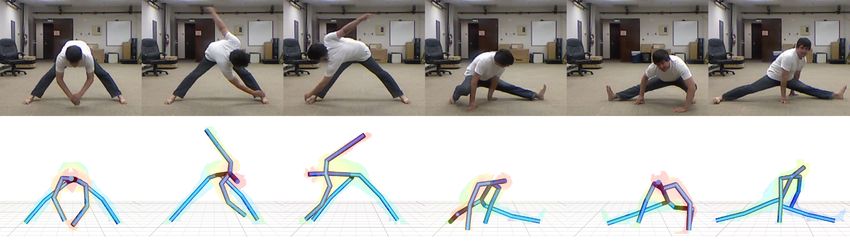
188:2       •      X. Wei et al.

one end, 3D pose tracking can produce more accurate results but                         Both systems focus on automatic realtime reconstruction of full-
often requires manual initialization and recovery. At the other end,                    body poses using a single depth camera. Like their system, we for-
3D pose detection can automatically infer 3D human poses from                           mulate 3D pose detection as a per-pixel classification problem and
single depth images but often with less accurate results. An ap-                        apply randomized decision trees to automatic pixel labeling. Our
propriate combination of both techniques provides benefits at both                      work, however, is significantly different from theirs in that we de-
ends. To achieve this, we introduce a hybrid motion capture scheme                      velop a realtime 3D tracking process to complement 3D pose detec-
that automatically switches between 3D pose tracker and 3D pose                         tion. Our system, therefore, shares the same advantages of Kinect
detector. We apply the 3D pose tracker to reconstruct the poses for                     but significantly improves the accuracy of the reconstructed poses.
all the frames except the starting frame and failure frames, which                      In addition, our solution of reconstructing 3D poses from classified
are initialized/reset by the 3D pose detector automatically. Such                       pixels is different from theirs. We explicitly remove the misclassi-
a combination not only automates the whole capturing process but                        fied pixels and apply our 3D tracking algorithm to reconstruct 3D
also improves the accuracy and robustness of the capturing system.                      poses in joint angle space, while their system estimates 3D joint
                                                                                        positions using probabilistic clustering techniques via meanshift.
We implement our hybrid algorithm on GPU to ensure the whole                            The comparison results show that our system produces much more
system runs in real time (44 frames per second). In addition, we                        accurate results than [Shotton et al. 2011] as well as the Kinect sys-
introduce a simple yet effective skeleton calibration process that                      tem [2012] for depth data with or without significant occlusions (see
automatically computes 3D human skeleton models from depth im-                          Section 7.2).
ages of a single reference pose. This enables the system to work for
subjects of different skeletal sizes. Our final system for full-body
motion capture is robust and fully automatic, runs in real time, and                    Our work builds upon the success of combining 3D pose track-
allows for accurate motion capture for different subjects.                              ing and detection to benefit from each other. Siddiqui and
                                                                                        Medioni [2010] combined bottom-up detection results and top-
We demonstrate the power and effectiveness of our system by cap-                        down likelihood in a data-driven MCMC framework for upper-body
turing a wide range of human movements in real time using a sin-                        pose estimation. Ganapathi and colleagues [2010] developed an in-
gle depth camera. Our system achieves state-of-the-art accuracy in                      teractive online motion capture system using a single depth camera.
our comparison against alternative systems such as [Kinect 2012;                        Their algorithm used body part proposals from [Plagemann et al.
Shotton et al. 2011; Ganapathi et al. 2010]. We assess the qual-                        2010] to track the skeleton with kinematic and temporal informa-
ity of reconstructed motions by comparing them with ground truth                        tion in a probabilistic framework. Baak et al. [2011] proposed to use
data simultaneously captured with a full marker set in a commer-                        detection results obtained from [Plagemann et al. 2010] to search
cial motion capture system [Vicon Systems 2011]. We also evalu-                         similar poses in a prerecorded motion database and combined pose
ate the importance of each key component of our 3D pose tracking                        hypothesis with local optimization to reconstruct the final solution.
process. And lastly, we evaluate the robustness of our system and                       Ye and colleagues [2011] utilized a data-driven pose detection tech-
analyze possible failure modes of the entire system.                                    nique to first identify a similar pose in the pre-captured motion
                                                                                        database and then refined the pose through non-rigid registration
1.1     Related Work                                                                    techniques. Our system is unique because it builds upon our highly
                                                                                        accurate 3D tracking algorithm and state-of-the-art 3D pose detec-
Our work builds upon a rapidly growing body of recent literature on                     tion algorithm. Our system is advantageous because it is robust and
3D pose tracking and detection with depth data. One possibility to                      fully automatic, runs in real time, and allows for accurate recon-
track 3D human poses is to sequentially register an articulated hu-                     struction of full-body poses even under significant occlusions.
man body model with depth data via Iterative Closest Point (ICP)
techniques. Grest and colleagues [2007] explored how to apply ICP                       Our work is related to techniques of tracking 3D human poses using
techniques to register an articulated mesh model with monocular                         conventional intensity/color cameras (for more details, we refer the
depth data along with silhouette correspondences between the hy-                        reader to [Moeslund et al. 2006]). One notable solution is to per-
pothesized and observed data. The ICP algorithm was also been                           form sequential pose tracking based on 2D image measurements
used in [Knoop et al. 2006] to fit a degenerated cylindrical 3D body                    (e.g., [Bregler et al. 2004]), which initializes 3D human poses at
model to depth data. However, the ICP algorithm is often sensitive                      the starting frame and sequentially updates 3D poses by minimiz-
to initial poses and prone to local minima, thereby failing to track                    ing the inconsistency between the hypothesized poses and observed
3D human poses from noisy depth data obtained from a single cam-                        measurements. This approach, however, is often vulnerable to oc-
era (for details, see comparison results in Section 7.2).                               clusions, cloth deformation, illumination changes, and a lack of
                                                                                        discernible features on the human body because 2D image mea-
An alternative solution is to take a bottom-up approach to pre-                         surements are often not sufficient to determine high-dimensional
dict/estimate 3D joint positions directly from a single depth im-                       3D human movement.
age. This approach is appealing because it does not assume any
3D human body model, does not require any pose initialization,
and does not get trapped in any local minima. For example, Plage-                       Our work is also relevant to recent efforts in realtime full-body
mann and colleagues [2010] constructed 3D meshes to detect inter-                       motion capture using only a few sensors [Chai and Hodgins 2005;
est points in depth images and then learned patch classifiers in order                  Slyper and Hodgins 2008; Liu et al. 2011; Tautges et al. 2011].
to automatically label them as “head”, “hands” or “feet”. Shotton                       Reconstructing human poses from a small number of sensors is of-
et al. [2011] formulated 3D pose estimation as a per-pixel classi-                      ten an ill-posed problem. One good way to reduce the ambigu-
fication problem and trained randomized decision trees based on a                       ity is to utilize prior knowledge embedded in prerecorded motion
large database of synthetic depth images rendered from prerecorded                      data. A number of researchers have explored how to utilize prere-
motion data for automatic pixel labeling. More recently, Girshick                       corded motion capture data to reduce the reconstruction ambiguity
and colleagues [2011] presented an efficient regression forest-based                    from low-dimensional control signals obtained from a sparse num-
method for detecting 3D human poses from single depth or silhou-                        ber of markers [Chai and Hodgins 2005] or inertial sensors [Slyper
ette images.                                                                            and Hodgins 2008; Liu et al. 2011; Tautges et al. 2011]. Our work
                                                                                        is different because we focus on markerless motion capture using a
Among all the systems, our work is most similar to [Shotton et al.                      single depth camera. Our system, therefore, is easy to set up and
2011], which forms a core component of the Kinect system [2012].                        requires no markers, no motion sensors, and no special suits.
ACM Transactions on Graphics, Vol. 31, No. 6, Article 188, Publication Date: November 2012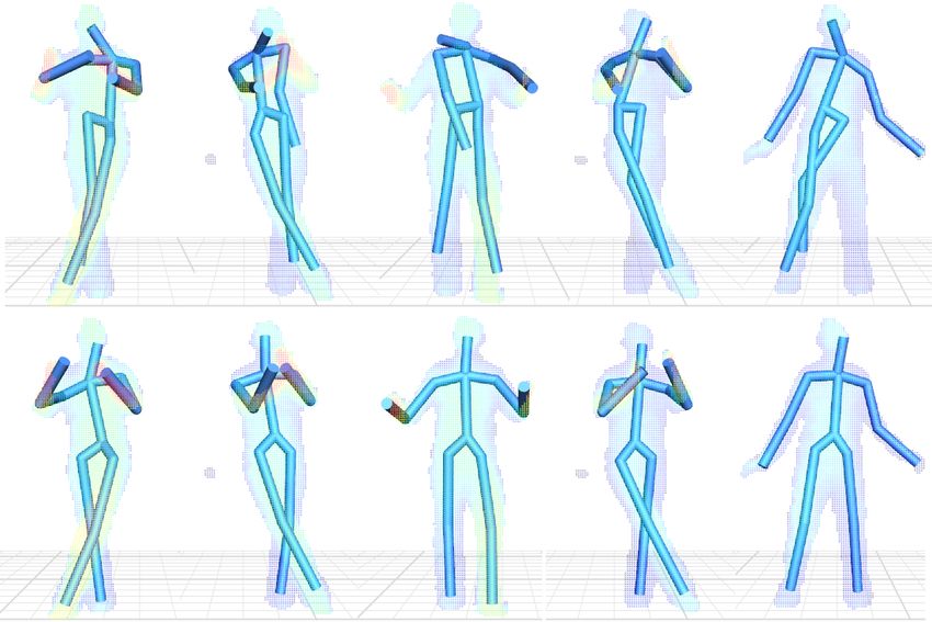
Accurate Realtime Full-body Motion Capture Using a Single Depth Camera                       •      188:3

                                                Yes    Error      No
                                                      drifting?

                                     3D Pose          3D Pose
             Acquisition
                                    Detection         Tracking

 Act out!                                                         3D motion

             Acquisition
                                    Skeleton                                    Figure 3: Our human skeleton models contain 15 bone segments.
                                   Calibration                                  We define a full-body pose using a set of independent joint coordi-
                                                                                nates q ∈ R34 , including absolute root position and orientation as
                                                                                well as the relative joint angles of individual joints.
  Posing

                     Figure 2: System overview.                                 2    Depth Data Acquisition and Preprocessing
                                                                                Current commercial depth cameras are often low-cost and can
1.2   Overview                                                                  record 3D depth data at a high frame rate. For example, Microsoft
                                                                                Kinect cameras, which cost roughly one hundred dollars, give a
                                                                                320 × 240 depth image at 30 frames per second (fps) with depth
We develop an automatic realtime system that accurately captures                resolution of a few centimeters. In our experiment, we have tested
3D full-body motion data using a single depth camera. Here we                   the system on depth data obtained from two types of depth cameras,
highlight the issues that are critical for the success of this endeavor         although our system is applicable to other types of depth cameras as
and summarize our approach for addressing them (see Figure 2).                  well. We recorded depth image data using a Swissranger SR4000
                                                                                Time-of-Flight camera, which was set to capture depth data at 25
3D pose tracking. The core of our system is a realtime tracking                 fps with a resolution of 176 × 144 pixels. We also employed the
process that accurately reconstructs 3D skeletal poses using input              Kinect camera for full-body motion capture. Pixels in a depth im-
data obtained from a single depth camera. Our idea is to formulate              age store calibrated depth data in the scene, rather than a measure
the problem in a Maximum A Posteriori (MAP) framework and in-                   of intensity or color. In our experiment, each pixel x = [u, v]t in
crementally register 3D skeletal poses with monocular depth data                the depth image stores not only the depth value D(x) but also the
via linear system solvers. One unique property of our tracking pro-             corresponding x-y-z coordinates p = [x, y, z]T in the 3D space.
cess is its sensible reasoning about occlusions in depth data. This
allows us to reconstruct 3D human poses under significant occlu-                Silhouette extraction. The system requires segmenting foreground
sions, a capability that has not been demonstrated in the state-of-             pixels from background pixels in depth images, though clean seg-
the-art systems such as Kinect [2012].                                          mentation results are not required for system success. We apply the
                                                                                background subtraction algorithm in the OpenCV library to remove
3D pose detection. 3D pose tracking often requires manual ini-                  background pixels for the Swissranger camera. For the Kinect cam-
tialization and recovery. This motivates us to develop a 3D pose                era, we use the Kinect API [2012] to extract foreground pixels. The
detection algorithm, which automatically infers 3D poses from sin-              system then converts foreground/background information into a bi-
gle depth images, to complement our tracking process. We for-                   nary silhouette image S(x) by setting foreground and background
mulate 3D pose detection as a per-pixel classification problem and              pixels to ones and zeros, respectively. The silhouette images S(x)
apply randomized decision trees [Amit and Geman 1997] to asso-                  will later be used for 3D tracking and detection.
ciate each depth pixel with particular bone segments. In addition,
we have introduced an efficient reconstruction technique to estimate            Full-body representation. We approximate full-body geometry
3D joint angle poses from classified depth pixels.                              with a human skeleton model of 15 rigid body segments (see Fig-
                                                                                ure 3). We approximate geometry of each bone segment with a
                                                                                cylindrical model except that the torso is modeled by an elliptic
Combining tracking with detection. Our final system combines
                                                                                cylinder. The full-body geometry model of a human figure can thus
the advantages of 3D pose tracking and detection. Specifically, we
                                                                                be defined by the radius and length of each bone segment. We de-
design a hybrid motion capture scheme that automatically switches
                                                                                scribe a full-body pose using a set of independent joint coordinates
between 3D pose tracker and 3D pose detector. We apply the 3D
                                                                                q ∈ R34 , including absolute root position and orientation as well
pose tracker to reconstruct the poses for all the frames except the
                                                                                as the relative joint angles of individual joints. These joints are the
starting frame and failure frames, which are initialized/reset by the
                                                                                head (3 Dof), lower neck (2 Dof), lower back (3 Dof), and left and
3D pose detector automatically. Such a combination not only auto-
                                                                                right clavicle (2 Dof), humerus (3 Dof), radius (1 Dof), femur (3
mates the whole capturing process but also significantly improves
                                                                                Dof), tibia (1 Dof).
the accuracy and robustness of the system.

Skeleton calibration. Skeleton calibration ensures the system                   3    Realtime 3D Pose Tracking
works for users of different skeletal sizes. We approximate the ge-
ometry of each bone segment with a cylindrical model. The calibra-              This section describes our tracking algorithm which sequentially
tion process automatically estimates the length and radius of cylin-            reconstructs 3D human poses q ∈ R34 from input depth data D(x)
drical models for each bone segment. Each user needs to perform                 and silhouette data S(x) obtained from a single depth camera. Our
the skeleton calibration step only once.                                        idea is to formulate the tracking problem in the MAP framework
                                                                                and iteratively register a 3D articulated human geometry model
We describe these components in detail in the next sections.                    with observed data via linear system solvers. In the following,
                                                                       ACM Transactions on Graphics, Vol. 31, No. 6, Article 188, Publication Date: November 2012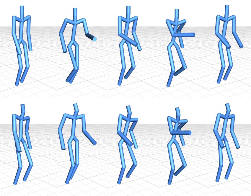
188:4       •      X. Wei et al.

                    (a)                                           (b)                                  (c)                                 (d)

Figure 4: Automatic labeling of depth pixels for likelihood evaluation. Black and gray circles represent the silhouettes of “observed” and
“rendered” depth images, respectively. The pixels used for evaluating the depth image term are visualized in red. (a) Without self-occlusion,
the depth image term is evaluated by pixels located in the overlapping region. (b) When self-occlusion occurs, pixels in region B2 need
to be excluded from the depth image term evaluation because they might be associated with different bone segments in the “rendered” and
“observed” images. (c) For all the non-red pixels which were excluded for the depth image term evaluation, we categorize them into four
different groups and use them to evaluate the extra depth term. Note that pixels in type “1”, “2”, “3” and “4” are visualized in green,
orange, magenta, and blue, respectively. (d) To evaluate the silhouette image term, we discard pixels with zero gradients and focus the
evaluation on the pixels with non-zero gradients in the foreground of the “rendered” region (see solid-blue pixels and half-blue pixels).

we explain how to incorporate depth data, silhouette information,                       the “hypothesized” depth data and “observed” depth data. Previ-
full-body geometry information, and pose priors into the MAP es-                        ous approaches (e.g., [Knoop et al. 2006; Grest et al. 2007]) often
timation framework. We also discuss how to incorporate occlusion                        apply Iterative Closest Points (ICP) techniques to find the corre-
reasoning into MAP estimation in order to handle significant occlu-                     spondences between the two. However, ICP techniques often pro-
sions caused by a single camera.                                                        duce poor results for human pose registration (for details, see Sec-
                                                                                        tion 7.2). To address this challenge, we project 3D depth data onto
Let Ci be the input data at the current frame i consisting of a depth                   the 2D image plane and register the “hypothesized” and “observed”
map Di and a binary silhouette image Si . We want to infer from                         depth images via image registration techniques, which avoids build-
Ci the most probable skeletal poses qi ∈ R34 for the current frame                      ing explicit correspondences between the two.
given the sequence of m previously reconstructed poses, denoted
as Qim = [qi−1 , ..., qi−m ]. Dropping the index i for notational                       In an analysis-by-synthesis loop, we first use the “hypothesized”
brevity, we aim to estimate the most likely poses q∗ by solving the                     joint angle pose q along with the 3D human body model to render
following MAP estimation problem:                                                       all the surface points on the human body. We define the 3D position
                                                                                        of a surface point as p = f(q; k, p0 ), where the vector function f
                     q∗ = arg max Pr(q|C, Qm ),                              (1)        is the forward kinematic function which maps the local coordinates
                               q
                                                                                        of the surface point p0 on the k-th bone segment to the global 3D
where P r(·|·) denotes the conditional probability.                                     coordinates p. For notational brevity, we denote the 3D global coor-
                                                                                        dinates of the “rendered” surface point as p(q). We further project
Using Bayes’ rule, we obtain
                                                                                        all the “rendered” 3D points p(q) onto 2D image space with the
                q∗ = arg max Pr(C|q, Qm )·P r(q|Qm ).                        (2)        calibrated camera parameters to obtain a “rendered” depth image
                          q                                                             Drender under the current camera viewpoint.
Assuming that C is conditionally independent of Qm given q, we
                                                                                        Assuming Gaussian noise with a standard deviation of σdepth for
can write
                                                                                        each depth pixel x, we obtain the following likelihood term for
                q∗ = arg max        Pr(C|q) · P r(q|Qm ),                    (3)        depth image registration:
                          q         | {z }        |    {z     }
                                Likelihood     Prior                                                 Y          1            kDrender (x(q), q) − D(x)k2
                                                                                        P r(D|q) =       √            exp(−                2
                                                                                                                                                           ),
where the first term is the likelihood term which measures how well                                         2πσdepth                    2σdepth
the reconstructed pose q matches the current observation data C,                                                                                        (4)
and the second term is the prior term which describes the prior                         where x(q) is a column vector containing the pixel coordinates of
distribution of the current pose q given the previous reconstructed                     the “rendered” depth image. Note that unlike color image registra-
poses Qm . Maximizing the posteriori produces a most probable                           tion, pixel values in the “rendered” depth image Drender are not
skeletal pose q∗ which is consistent with both observation data C                       fully dependent on pixel coordinates x(q) because the depth values
and previous reconstructed poses Qm .                                                   of pixels also directly vary with the reconstructed pose q. This is
                                                                                        due to reparameterization of 3D point data p(q) on 2D image space.
We adopt an “analysis-by-synthesis” strategy to measure how well
the reconstructed poses q match observed data C, including depth                        A critical issue for the depth image term evaluation is to determine
data D and silhouette data S. By assuming conditional indepen-                          which pixels in the “rendered” image should be included for eva-
dence, we can model the likelihood distribution in Equation 3 as the                    lution. This is very important to our tracking process because we
product P r(C|q) = P r(D|q)P r(S|q). The two factors capture                            adopt gradient-based methods for MAP estimation. Including in-
the alignment of reconstructed poses with depth data and silhouette                     appropriate pixels into the depth image term will mislead MAP es-
data, respectively. The rest of this section focuses on discussion                      timation and cause the optimizer to fall in local minima. A simple
on how to model P r(D|q) and P r(S|q), as well as the prior term                        solution is to use all the foreground pixels, denoted as x ∈ R, in
P r(q|Qm ). We model the distribution of each term as a product of                      the “rendered” depth images (Figure 4(a)). This solution, however,
Gaussians, treating each pixel from input data independently.                           often causes inappropriate updates to the current poses because a
                                                                                        foreground pixel in the “rendered” depth image might be located in
Depth image term. In general, the evaluation of the likelihood                          the background region of the “observed” depth image. To address
term P r(D|q) requires identifying the correspondences between                          the issue, our system automatically excludes those pixels from the
ACM Transactions on Graphics, Vol. 31, No. 6, Article 188, Publication Date: November 2012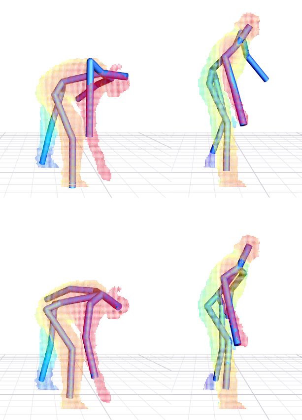
Accurate Realtime Full-body Motion Capture Using a Single Depth Camera                       •       188:5

depth term evaluation by checking whether a foreground pixel in               the “rendered” and “observed” depth images also contain corre-
the “rendered” image is located in the background region of the               sponding x-y-z coordinates in 3D space. In our implementation,
“observed” image. In Figure 4(a), those pixels are located in region          we find the closest points with bidirectional distance measurement
B1 = {x ∈ R; x 6∈ O}, where region O includes all foreground                  to ensure one-to-one correspondences. Meanwhile, we exclude the
pixels in the “observed” image.                                               correspondences from the extra depth term evaluation if their depth
                                                                              differences are larger than a specific threshold (8 cm). The “ar-
When self-occlusion occurs, a pixel located in the overlapping re-            rows” in Figure 4(c) visualize the correspondences associated with
gion R ∩ O might associate with different bone segments in the                each type of pixels.
“rendered” and “observed” images. Imagine crossing the left arm
in front of the chest. Some pixels on the “left arm” in the “rendered”        We now can define the extra depth term as follows:
image might inevitably overlap the “chest” pixels in the “observed”
image. We illustrate the situation in Figure 4(b), where the “left
                                                                                                       Y       1            kp(q) − p∗ k2
                                                                                 P rextra (D|q) =           √         exp(−      2
                                                                                                                                          ),               (5)
arm” and “chest” are visualized as the “small” elliptical region and                                         2πσextra         2σextra
“large” elliptical region, respectively. Similarly, those pixels would        where p(q) is a 3D point in the “rendered” depth image and p∗ is
mislead M AP estimation and should be excluded from evalua-                   the closest point in the “observed” depth image.
tion because they are associated with different bone segments in
the “rendered” and “observed” depth images. In our experiment,                Silhouette image term. The silhouette image term P r(S|q) en-
we adopt a simple yet effective idea to detect those pixels, denoted          sures that the “rendered” silhouette map Srender matches the “ob-
as x ∈ B2 (Figure 4(b)). We calculate the depth difference for                served” silhouette map S extracted from input depth data. This
each pixel in the overlapping region and exclude the pixels from              term complements the depth image term and extra depth term, nei-
the depth image term evaluation if their depth differences are larger         ther of which penalizes the mismatch between the “rendered” and
than a specific threshold, which is experimentally set to 8 cm. In            “observed” silhouette images. The silhouette image term is particu-
Figure 4(b), we visualize all the pixels G = {x ∈ R; x 6∈ B1 ∪B2 }            larly helpful for tracking human poses under significant occlusions.
used for the depth image term evaluation in red.                              Figure 11 in Section 7.3 shows the importance of the silhouette im-
                                                                              age term.
Extra depth term. In practice, even with ground truth poses, the
“rendered” depth images might not precisely match the “observed”              Similarly, evaluating the silhouette image term requires building
depth images due to camera noise, cloth deformation, and an ap-               the correspondences between the “rendered” and “observed” sil-
proximate modeling of full-body geometry. As a result, the depth              houettes. We choose to evaluate the silhouette image term on 2D
image term alone is often not sufficient to produce satisfactory re-          image space in the same way as the depth image term. This avoids
sults, particularly when significant occlusions occur. This motivates         finding explicit correspondences between the “rendered” and “ob-
us to introduce an extra depth term to evaluate all the depth pixels          served” silhouettes, and therefore is less prone to local minima. As-
that were excluded from the depth image term evaluation. Besides              suming Gaussian noise with a standard deviation of σsilhouette for
the region B1 and B2 , we will also consider the pixels in the region         each pixel x ∈ R, we obtain the likelihood term for silhouette reg-
B3 = {x ∈ O; x 6∈ R}.                                                         istration:
We categorize all the pixels that were excluded from the depth im-                           Y              1           kSrender (x(q)) − Sk2
                                                                              P r(S|q) =           √                  exp(−                    ),
age term evaluation, denoted as x ∈ B1 ∪ B2 ∪ B3 , into four dif-                                 2πσsilhouette                  2
                                                                                                                              2σsilhouette
ferent groups and use them to obtain a number of correspondences                                                                               (6)
between the “rendered” depth data and the “observed” depth data               where x(q) represents 2D pixel coordinates in the “rendered” sil-
as follows (Figure 4(c)):                                                     houette image. Since our system applies iterative gradient solvers
                                                                              to estimate the reconstructed poses, we can discard pixels with zero
Type 1. For a “rendered” pixel x(q) ∈ B1 , we find the closest point
                                                                              gradients and focus the evaluation on the pixels with non-zero gra-
xc1 ∈ O in the “observed” data and push the “rendered” pixel x(q)
                                                                              dients (see solid-blue and half-blue pixels in Figure 4(d)).
towards the “observed” pixel xc1 (“green” arrow).
Type 2. For an “observed” pixel x ∈ B3 , we search the closest                Prior term. We evaluate the prior term P r(q|Qm ) by measur-
point xc2 (q) ∈ R in the “rendered” depth image and pull the “ren-            ing how well the current pose q is placed after previous m poses
dered” pixel xc2 (q) to the “observed” pixel x (“orange” arrow).              [q̃−1 , ..., q̃−m ]. We assume that the pose at the current time de-
                                                                              pends only on the poses at previous two frames. The prior term
Type 3. For a “rendered” pixel x(q) ∈ B2 , if its “rendered” depth            is
value is smaller than its “observed” depth value, then the “ob-                                      1        −kq − 2q̃−1 + q̃−2 k                   2
served” pixel is occluded by the “rendered” pixel. Therefore, we                      P r(q|Qm ) = √     exp(                      ),                      (7)
use the “rendered” pixel x(q) to find the closest point xc3 ∈ O in                                  2πσs              2σs2
the “observed” image and push the “rendered” pixel x(q) towards               where q̃−1 and q̃−2 are the reconstructed poses in the previous two
the “observed” pixel xc3 (“magenta” arrow).                                   frames. The prior term assumes a constant acceleration model and
                                                                              thus penalizes the velocity change of 3D human poses.
Type 4. For a “rendered” pixel x(q) ∈ B2 , if its “rendered” depth
value is larger than the “observed” depth value, then the “rendered”
pixel is occluded by the “observed” pixel. We thus use the “ob-               3.1     Realtime Optimization
served” pixel x to search the closest point xc4 (q) ∈ R in the “ren-
dered” depth image and pull the “rendered” pixel xc4 (q) to the “ob-          We solve the MAP estimation problem defined in Equation (3) by
served” pixel x (“blue” arrow).                                               minimizing the negative logarithm of the posteriori probability den-
                                                                              sity function, yielding the following energy minimization problem:
We define the extra depth term in 3D space instead of 2D image
space. This is because the extra depth term is defined for pixels                q∗ = arg min Edepth + Eextra + Esilhouette + Eprior                       (8)
                                                                                           q
located in non-overlapping regions while correspondence informa-
tion in non-overlapping regions cannot be estimated on 2D image               where
space via image gradients. We find the correspondences by di-                                               kDrender (x(q), q) − Dk2
                                                                                              Edepth =                               ,                     (9)
rectly searching the closest points in 3D space as depth pixels in                                                     2
                                                                                                                    2σdepth
                                                                     ACM Transactions on Graphics, Vol. 31, No. 6, Article 188, Publication Date: November 2012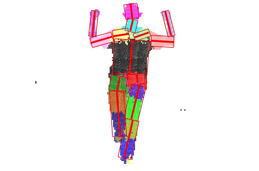
188:6       •      X. Wei et al.

                                     kp(q) − p∗ k2
                        Eextra =          2
                                                   ,                       (10)
                                       2σextra

                                   kSrender (x(q)) − Sk2
                Esilhouette =             2
                                                         ,                 (11)
                                       2σsilhouette

                                kqi − 2q̃i−1 + q̃i−2 k2
                   Eprior =                             .                  (12)
                                         2σs2

This requires minimizing a sum of squared nonlinear function val-
ues. Our idea is to extend the Lucas-Kanade algorithm [Baker and                                (a)                (b)               (c)                (d)
Matthews 2004] to solve the above non-linear least squares prob-
lem. Lucas-Kanade algorithm, which is a Gauss-Newton gradient                           Figure 5: 3D pose detection and reconstruction: (a) classified pix-
descent non-linear optimization algorithm, assumes that a current                       els; (b) classified pixels after outlier removal; (c) pose reconstruc-
estimate of q is known and then iteratively solves for increments to                    tion with inverse kinematics; (d) 3D pose refinement via tracking.
the parameters δq using linear system solvers.
In our implementation, we initialize the current pose using the pre-
viously estimated pose and iteratively perform the following steps                      divided into two classes to allow for more accurate detection of 3D
until the change of the pose is smaller than a specified threshold:                     poses. At runtime, given an input patch w(xinput ) centered at a
                                                                                        “foreground” depth pixel xinput ∈ O, we want to decide whether
    • Step 1: Given the current pose q and the full-body human                          or not its measurement matches one of the N classes of pixels. In
      mesh model, we render a depth image Drender (x(q), q) and                         other words, we want to find for w(xinput ) its class label Y (w) ∈
      a silhouette image Srender (x(q)) under the current camera                        C = {1, 2, ..., N }.
      viewpoint.
                                                                                        In practice, no classifier is perfect. The classified pixels are often
    • Step 2: For a pixel x ∈ R in the “rendered” depth image, we                       noisy and frequently corrupted by outliers due to classification er-
      use OpenGL’s selection buffer to determine which bone seg-                        rors (see Figure 5(a)). We, therefore, develop an efficient technique
      ment (k) the pixel is associated with as well as the local co-                    to automatically remove misclassified pixels (Figure 5(b)). We then
      ordinates of the corresponding surface point (p0 ) on the k-th                    process the classified depth pixels to compute the centroid of each
      bone segment. This step is necessary for evaluating the partial                   labeled cluster and reconstruct the pose in joint angle space with
      derivatives ∂p/∂q because the global coordinates of surface                       inverse kinematics techniques (Figure 5(c)). Lastly, we apply the
      points p = f(q; k, p0 ) are dependent on the local coordinates                    3D tracker described in Section 3 (Figure 5(d)) to refine the recon-
      p0 as well as the associated bone segment k.                                      structed poses. We discuss each step in detail in the rest of this
    • Step 3: We calculate the gradients of the “rendered” depth                        section.
      image and the “rendered” silhouette image and other partial
      derivatives in Equations (9), (10), (11), and (12) to form linear                 4.1   Automatic Pixel Labeling with Randomized Trees
      equations (for details, see Appendix A).
    • Step 4: We compute the optimal increment δq using linear                          We use randomized decision trees [Amit and Geman 1997] to train
      system solvers and update the current pose: q = q + δq.                           a classifier for automatic labeling of depth pixels. We advocate the
                                                                                        use of randomized trees because they naturally handle multi-class
The algorithm usually converges within five iterations as we initial-                   problems and are robust and fast, while remaining reasonably easy
ize the solution using the previous reconstructed poses.                                to train. A randomized forest is an ensemble of L decision trees
                                                                                        T1 , ..., TL . Each node in the tree contains a simple test that splits
Realtime GPU implementation. The fact that each step in the                             the space of data to be classified, in our case the space of depth
tracking algorithm can be executed in parallel allows implementing                      patches. Each leaf contains an estimate based on training data of
a fast solver on modern graphics hardware. By using CUDA to im-                         the posterior distribution over the classes. A new patch is classified
plement our tracking algorithm, the current system runs in real time                    by dropping it down the tree and performing an elementary test at
(48 frames per second) on a machine with Intel Core i7 3.40GHz                          each node that sends it to one side or the other. When it reaches a
CPU and GeForce GTX 580 graphics card. For each iteration, the                          leaf, it is assigned probabilities of belonging to a class depending
typical computational times for rendering depth/silhouette images,                      on the distribution stored in the leaf.
forming and solving linear questions are about 1ms, 1.6ms, and
1.4ms, respectively.                                                                    Once the trees T1 , ..., TL are built, their responses are combined
                                                                                        during classification to achieve a better recognition rate than a sin-
4    3D Pose Detection                                                                  gle tree could. More formally, the tree leaves store posterior proba-
                                                                                        bilities Prλ(l,w) (c|w), where c is a label in C and λ(l, w) is the leaf
                                                                                        of tree Tl reached by the patch w. Such probabilities are evaluated
One limitation of the tracking process is that it requires manual ini-
                                                                                        during training as the ratio of the number of patches of class c in the
tialization of the starting poses. In addition, it cannot automatically
                                                                                        training set that reach λ and the total number of patches that reach
recover from failures once the system gets stuck in the local mini-
                                                                                        λ. The whole forest achieves an accurate and robust classification
mum. This section describes an efficient 3D pose detection process
                                                                                        by averaging the class distributions over the leaf nodes reached for
for automatic initialization/reset of our 3D pose tracking process.
                                                                                        all L trees:
Similar to [Shotton et al. 2011], we formulate the 3D pose detection                                               1 X
problem as a per-pixel classification problem. During training, we                                  c̃ = arg max               Prλ(l,w) (c = Y (w)).       (13)
                                                                                                               c  L
construct a set K = {k1 , ..., kN } of N classes of pixels. Each class                                              l=1,...,L
corresponds all pixels located on a particular bone segment except
for low-body bone segments, where upper legs and lower legs are                         Node testing. The tests performed at the nodes are simple binary
ACM Transactions on Graphics, Vol. 31, No. 6, Article 188, Publication Date: November 2012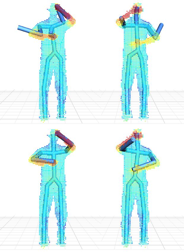
Accurate Realtime Full-body Motion Capture Using a Single Depth Camera                       •      188:7

tests based on simple functions of raw pixels taken in the neighbor-            total number of pixels within the projection region of each bone,
hood of the classification pixel. Similar to [Lepetit and Fua 2006],            but we found 2500 samples to be more than enough for all of the
our feature function calculates the difference of depth values of a             testings we tried. Figure 5(b) shows the classified depth pixels after
pair of pixels taken in the neighborhood of the classification pixel            outlier removal.
x: D(x + ∆x1 ) − D(x + ∆x2 ). We normalize the offset of each
pixel (i.e., ∆x1 and ∆x2 ) by its depth value D(x) to ensure the fea-           3D pose reconstruction and refinement. We now can apply in-
tures are depth invariant. If the value of a splitting function is larger       verse kinematics techniques to transform classified depth pixels to
than a threshold, go to left child and otherwise go to right child. In          a 3D joint angle pose. We calculate the centroid of all the inlier
all our experiments, the patches are of size 50 × 50. And the opti-             pixels categorized into each of the classes and use them as kine-
mal threshold for splitting the node is automatically determined by             matic constraints for 3D pose estimation. However, when only a
maximizing the information gain for particular features.                        small percentage of inliers are detected or bone segments are self
                                                                                occluded, the solution becomes noisy due to inaccurate centroid
Training data. To learn a classifier for automatic depth pixel label-           locations (see Figure 5(c)). We apply the 3D tracker described in
ing, we need to construct a training database containing a large set            Section 3 to refine the solution. Figure 5(c) and (d) show the recon-
of synthetic depth images. Every pixel in the depth images needs to             structed pose before and after 3D pose refinement.
be annotated with an appropriate class label c ∈ 1, ..., N . To con-
                                                                                Realtime GPU implementation. We achieve realtime perfor-
struct the training database, we first use a polygon mesh model to
                                                                                mance (about 44 fps) by executing every step of 3D pose detection
render “synthetic” depth images corresponding to different poses,
                                                                                process in CUDA. The computational times for pixel classification,
camera viewpoints, and human skeletal models. Synthetic depth
                                                                                outlier removal, and 3D pose reconstruction and refinement (three
pixels are automatically annotated with class information because
                                                                                iterations) are about 3.3ms, 6.7ms, and 13ms, respectively.
every pixel in the “rendered” depth images is associated with a par-
ticular bone segment thus a class label. Our training database con-
sists of approximately 20k poses from 65 sequences of human ac-                 5    Combining Tracking with Detection
tions such as dancing, sitting, kicking, running, boxing, and tennis.
                                                                                This section discusses how to combine 3D pose tracker with 3D
Randomized trees learning. We use the randomized trees algo-                    pose detector to improve the robustness and accuracy of our full-
rithm to learn binary forests. Each tree is trained separately on a             body motion capture system. One possible solution is to apply the
small random subset of the training data. The trees are constructed             3D pose detector to every single depth image and then refine the re-
in the classical, top-down manner, where the tests are chosen by                constructed poses using the 3D pose tracker. While such a combi-
a greedy algorithm to best separate the given examples. At each                 nation produces a fully automatic reconstruction system, the quality
node, several candidates for a feature function are generated ran-              of the reconstructed poses is highly dependent on the accuracy of
domly, and the one that maximizes the expected gain in informa-                 3D pose detectors. When significant occlusions occur, the system
tion about the node categories is chosen. The process of selecting a            often produces poor results because current 3D pose detectors often
test is repeated for each nonterminal node, using only the training             fail to handle occlusions effectively.
examples falling in that node. The recursion is stopped when the
node receives too few examples, or when it reaches a given depth.               In practice, a majority of frames can be successfully tracked by
                                                                                our tracking process while only a few frames require 3D pose
                                                                                re-initialization. This observation leads us to apply the 3D pose
4.2   Automatic 3D Pose Reconstruction                                          tracker to reconstruct the poses for all the frames except the start-
                                                                                ing frame and failure frames, which can be initialized/reset by the
Our next task is to infer a 3D joint angle pose from classified depth           3D pose detector. Briefly, the system first uses the detector to ini-
pixels. One way to achieve this is to estimate the centroid of each             tialize the starting pose of the tracker and invokes the tracker to
class and use them for finding the inverse kinematics solution. In              sequentially register 3D skeletal poses to input data. The system
practice, no classifier is perfect, so kinematic constraints derived            automatically monitors the status of the tracker. Once it detects the
from the classified pixels are often noisy and frequently corrupted             “failure” mode, the system switches back to the detector, uses the
by outliers due to classification errors. Figure 5(a) shows the clas-           detector to re-initialize the tracker, and then starts a new tracker for
sification result on a test depth image. It is noticeable that some             online motion reconstruction.
pixels on the “left arm” are misclassified to the “left leg” while
some pixels on the “left leg” are incorrectly labeled as the “torso”.           A remaining issue is to determine when the tracker fails and when
In practice, direct use of the classified pixels for joint angle pose           to switch to the detector. The system automatically identifies track-
estimation often produces noisy reconstruction results.                         ing failures by measuring how well the reconstructed poses match
                                                                                the current input data, which is achieved by evaluating the sum of
Outlier removal. To address the issue, we formulate the problem                 the likelihood terms defined in Equation (9), (10) and (11). To be
as a robust fitting problem and apply random sampling techniques                specific, the system automatically switches to the detector if one of
to automatically detect and remove misclassified depth pixels. We               the following two conditions is satisfied:
choose random sampling techniques because it allows for robust
fitting of a model (i.e. a rigid-body bone segment in our applica-                  • when the “rendered” depth data is not consistent with the “ob-
tion) in the presence of a high percentage of outliers. Specifically,                 served” depth data. More specifically, if the average error for
we parameterize the location and orientation of each bone segment                     the depth image term and extra depth term is higher than a
with two end points (i.e. inboard and outboard joints) and fit to the                 specific threshold 1 , the system will automatically switch to
classified depth pixel by randomly selecting a pair of depth pixels                   the “detector”.
associated with the same class and counting the number of inliers                   • when the silhouette image term is not well satisfied. On other
(i.e. the number of “foreground” depth pixels that are located on or                  words, the number of pixels in the overlapping region (R ∩O)
within the bone segment). To speed up the robust fitting process,                     is smaller than a certain percentage 2 of the total number of
we discard random samples without counting the number of inliers                      pixels in the region R ∪ O.
if the Euclidean distance between the selected depth pixels is larger
than the bone length or smaller than one fifth of the bone length.              The specific thresholds often depend on sensor noise, the size and
The exact number of samples for each bone heavily depends on the                proportions of full body geometric models, and the accuracy of
                                                                       ACM Transactions on Graphics, Vol. 31, No. 6, Article 188, Publication Date: November 2012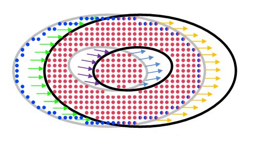
188:8       •      X. Wei et al.

                                                                                                             Ganapathi et al.   Shotton et al.   Our Algorithm
                                                                                              1

                                                                                             0.9

                                                                                             0.8

                                                                                             0.7

                                                                                             0.6

                                                                                             0.5

                        (a)                         (b)

Figure 6: Automatic skeleton calibration. (a) the per-pixel labeling
result on the calibration pose; (b) the calibrated bone segments                        Figure 7: Comparison against Shotton et al. [2011] and Ganapathi
(before averaging over symmetric bones).                                                et al. [2010]. The vertical bars show the estimation accuracy of
                                                                                        different joints from three different algorithms.

skeleton geometric models. Since our system provides realtime
feedback, we can experimentally determine suitable values that                          7          Results
achieve stable performance. For all our results we use the same
settings: 1 = 2.5 cm and 2 = 90%.                                                     In this section, we demonstrate the power and effectiveness of our
                                                                                        system by capturing a wide range of human movements using a sin-
                                                                                        gle depth camera (section 7.1). Our comparison against alternative
6    Automatic Skeleton Calibration                                                     methods shows the system achieves state-of-the-art accuracy (Sec-
                                                                                        tion 7.2). We assess the performance of our tracking process by
In this section, we introduce an automatic skeleton calibration                         dropping off each term in the cost function (Section 7.3). Finally,
method to ensure the system works for users of different skele-                         we evaluate the robustness of the entire system and examine its po-
tal sizes. We approximate geometry of each bone segment with                            tential failures by testing on the user playing a number of Kinect
a cylindrical model except the torso, which is modeled by an el-                        games (Section 7.4).
liptic cylinder. We choose to approximate geometry of each bone
segment with cylindrical models because they are easy to general-                       7.1        Test on Real Data
ize to full-body geometry of different users. The calibration process
automatically estimates the length and radius of cylindrical models                     We have evaluated our system on two types of depth cameras:
for each bone segment (Figure 6). Each user needs to perform the                        Kinect camera and SwissRanger SR4000 Time-of-Flight camera.
skeleton calibration step only once.                                                    We test the system on capturing a wide range of human activities,
The whole process consists of two steps:                                                including locomotion such as walking and running, sports activities
                                                                                        such as warming up exercises, golf, tennis, soccer, and Tai-Chi, and
    • We instruct the subject to perform a reference pose shown                         everyday actions such as picking, sitting on ground, kicking, danc-
      on the screen. We apply the randomized decision trees de-                         ing, arm crossing, and hand clapping. Our results are best seen
      scribed in Section 4.1 to automatically label input depth pix-                    in video form, although we show several frames of a few results
      els. Unlike the 3D pose detection process, here we restrict                       here. In the video, we annotate the results obtained from Kinect
      the training data sets of randomized trees to the calibration                     and SwissRanger with “KS” and “SR”, respectively.
      pose only and therefore achieve more accurate pixel labeling
      results (Figure 6(a)).                                                            The system works for users with different body size and propor-
                                                                                        tions. The accompanying video includes the reconstruction results
    • To remove the effect of misclassified pixels, we adopt a sim-                     from six different subjects, including five males and one female.
      ilar random sampling technique described in Section 4.2.                          Another notable feature of the system is to handle significant oc-
      Briefly, for each bone segment, we randomly sample a ra-                          clusions caused by a single depth camera. We show the system can
      dius value and select a pair of depth pixels associated with                      accurately capture a wide range of human movements even in the
      the bone. The sampled radius value and the pair of depth pix-                     case of significant occlusions, including sitting down on the ground,
      els define a cylinder in 3D space. We evaluate each sample by                     standing up, Tai-Chi, kicking, picking, walking with 360-degrees ro-
      counting the number of inliers Ni and outliers Ñi within the                     tation, arm crossing, and so on. For example, in the “arm crossing”
      2D projection of the sampled cylinder. Mathematically, we                         example, we demonstrate that the system is able to track complex
      define the following cost function to evaluate each sample:                       arm movements even in the case of significant occlusions. Note that
                                                                                        the “detector” in our system was triggered only once to initialize the
                                   Q = Ni − Ñi                            (14)         starting pose for capturing the “arm crossing” action.
      where Ni are the number of depth pixels associated with bone
      i (i.e. inliers) and Ñi is the total number of pixels which are                  7.2        Comparisons Against Alternative Methods
      not associated with bone i, including both misclassified pixels
      and background pixels.                                                            We have evaluated the performance of our system by comparing
                                                                                        against alternative methods.
We implement the whole skeleton estimation process in CUDA,
which provides realtime feedback on the calibrated skeleton. To                         Comparison against [Shotton et al. 2011; Ganapathi et al.
improve the accuracy of our calibration process, we assume sym-                         2010]. The authors of [Ganapathi et al. 2010] provided their
metric human skeletons and average the parameters estimated from                        test data and results for direct comparison. Shotton and col-
the left and right limbs.                                                               leagues [2011] also evaluated their algorithm on the same data sets.
ACM Transactions on Graphics, Vol. 31, No. 6, Article 188, Publication Date: November 2012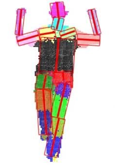
Accurate Realtime Full-body Motion Capture Using a Single Depth Camera • 188:9
Figure 8: Comparison against Kinect [2012]. (top) reference image data; (middle) Kinect results; (bottom) our results.
ison on capturing human movements in the presence of significant
occlusions because almost all the benchmark data sets [Ganapathi
et al. 2010] in the previous comparison do not involve signifi-
cant occlusions. The accompanying video highlights a side-by-side
comparison between our system and Kinect. Figure 8 shows several
sample frames for a side-by-side comparison between our result and
the result obtained by Kinect. The comparison results clearly show
the advantage of our system over Kinect. Note that the Kinect sys-
tem [2012] builds on Shotton et al. [2011].
Comparison against ICP techniques. We also compare our 3D
pose tracking process described in Section 3 with Iterative Clos-
est Point (ICP) techniques [Knoop et al. 2006; Grest et al. 2007].
We start both algorithms with the same initial pose. The compar-
ison result shows that our tracking process is much more robust
and accurate than the ICP algorithm. In the hand clapping example
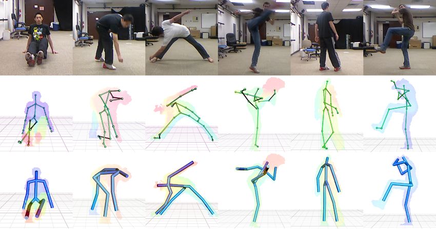
Figure 9: Comparison against ICP. (top) the result obtained from shown in Figure 9, our tracking process successfully tracks the en-
the ICP algorithm; (bottom) our result. tire motion sequence while ICP fails to track most of frames. This
is because ICP is often sensitive to initial poses and prone to local
minimum, particularly involving tracking high-dimensional human
In this experiment, we make a comparison between our method and body poses from noisy depth data.
[Shotton et al. 2011; Ganapathi et al. 2010]. Figure 7 shows our al-
gorithm significantly improves average precision of reconstruction Comparison against Vicon [2011]. In this experiment, we quan-
results. Our comparison is based on the same evaluation metric as titatively assess the quality of the captured motion by comparing
in [Ganapathi et al. 2010; Shotton et al. 2011]. In particular, the with ground truth motion data captured with a full marker set in
bars in Figure 7 show estimation accuracy of different joints. The a twelve-camera Vicon system [2011]. The average reconstruction
joint position within D meters of the ground truth is counted as error, which is computed as average 3D joint position discrepancy
“true positive” (correct). Otherwise, it is counted as “false posi- between the estimated poses and the ground truth mocap poses, was
tive”. The precision of one joint is the fraction of joint positions about 5.0 cm per joint per frame. Figure 10 shows a side-by-side
that are correct (within D meters of the ground truth). We set D comparison between our result and the result obtained by Vicon.
to 0.1m. This is because Ganapathi and colleagues [2010] found
that individual marker errors of 10 cm or lower can be interpreted 7.3 Evaluation on Tracking Process
as perfectly tracked markers, since this corresponds to the approxi-
mate accuracy of the recorded ground truth data. We have evaluated the performance of our tracking process by drop-
ping off each term of the cost function described in Equation 8.
Comparison against Kinect [2012]. We compare the system
against the state-of-the-art in motion capture using a single depth The importance of occlusion handling. We compare results ob-
camera [Kinect 2012]. We download the most recent version of Mi- tained by the tracking process with or without “occlusion handling”
crosoft Kinect for windows [2012] and test both systems on captur- (See Figure 11(a)). Tracking without “occlusion handling” includes
ing a wide range of human movements. Here, we focus our compar- all the pixels in x ∈ B2 to evaluate the depth image term. In con-
ACM Transactions on Graphics, Vol. 31, No. 6, Article 188, Publication Date: November 2012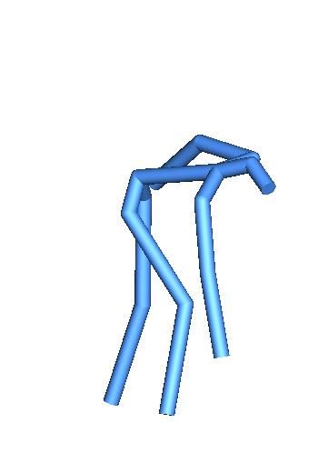
188:10        •      X. Wei et al.

                                                                                                Kinect games        Tracking failure pct    System failure pct
                                                                                                 Adventure                0.17%                     0
                                                                                                  Star War                0.26%                     0
                                                                                                 Fruit Ninja              0.23%                  0.01%
                                                                                             Dance Central (easy)         0.35%                  0.01%
                                                                                             Dance Central (hard)         1.28%                  0.52%
                                                                                                  Average                 0.46%                  0.11%

                                                                                                      Table 1: Evaluation of system robustness.

                                                                                        centage of the total frames which were switched to the detector.
                                                                                        The tracking failure percentage indicates the effectiveness of the
                                                                                        tracking process. On average, 0.46% of the total frames were re-
Figure 10: Comparison against Vicon [2011]. (top) ground truth                          initialized by the detector while the rest of the frames were au-
data captured with a full marker set in a twelve-camera Vicon sys-                      tomatically reconstructed by the tracker. This confirms our as-
tem; (bottom) our result.                                                               sumption that a majority of frames can be successfully recon-
                                                                                        structed by 3D tracker while only a few frames require 3D pose
                                                                                        re-initialization. We have observed two typical failure modes in the
                                                                                        tracking system. The tracking system often gets stuck in local min-
                                                                                        ima and fails to produce good results when tracking extremely fast
                                                                                        movement due to poor initialization of the tracking poses and noisy
                                                                                        depth measurement caused by fast motion. In addition, the system
                                                                                        might fail to reconstruct accurate joint angle poses for disoccluded
                                                                                        bone segments. This is mainly because of poor initialization of the
                                                                                        current poses. Note that we initialize the current poses using the
                                                                                        previous poses. However, when a bone segment is not visible to
                                                                                        the current camera, its 3D joint angle value is often ambiguous and
                                                                                        cannot be reliably estimated.
                                                                                        System failure analysis. We evaluate the robustness of the entire
                                                                                        system by calculating the percentage of the total failure frames. In
                                                                                        our evaluation, we ask the user to manually label all failure frames
                                                                                        across the entire sequence of each testing motion. The system fail-
                                                                                        ure percentage measures the effectiveness of the whole system as
                   (a)                                        (b)                       neither tracking process nor detection process is able to estimate the
                                                                                        pose reliably. The average system failure percentage is about 0.1%
Figure 11: Evaluation on the tracking process. (a) the importance                       (about 1 failure pose every 33 seconds). The whole system fails
of occlusion handling: the top and bottom rows show the tracking                        when neither tracking process nor detection process is able to pro-
results with and without occlusion handling. (b) the importance                         duce good results. The detection system often fails to generate good
of the silhouette image term: the top and bottom rows show the                          results when the testing pose is very different from training data sets
tracking results with and without the silhouette term.                                  and/or when human bodies are under significant occlusions.

                                                                                        8      Conclusion
trast, tracking with “occlusion handling” excludes all the pixels in
x ∈ B2 from the depth image term evaluation and instead includes                        In this paper, we have developed an end-to-end full-body motion
them into the extra depth term evaluation. Our video shows that                         capture system using a single depth camera. Our system is appeal-
tracking without “occlusion handling” gets stuck in wrong results                       ing because it is low-cost and fully automatic, runs in real time,
several seconds after the tracking starts. With “occlusion handling,”                   and can accurately reconstruct 3D poses even in the case of signif-
the algorithm can accurately reconstruct 3D poses across the entire                     icant occlusions. The system is also non-intrusive and easy to set
sequence.                                                                               up because it requires no markers, no sensors, and no special suits.
The importance of silhouette image term. We evaluate the impor-                         We have demonstrated the power of our approach by capturing a
tance of the silhouette image term. The side-by-side comparison in                      wide range of complex human movements. The system achieves
Figure 11(b) shows that the silhouette image term ensures better                        state-of-the-art accuracy in our comparison against Kinect.
silhouette registration, thereby producing more accurate results for                    Complementing tracking with detection not only automates the cap-
the reconstructed poses.                                                                turing process but also improves the accuracy and robustness of the
                                                                                        whole system. Our framework for combining human pose tracking
7.4    Evaluation of System Robustness                                                  and the detection process is very flexible. We believe that any effi-
                                                                                        cient 3D pose detector such as [Shotton et al. 2011] can be plugged
We have evaluated the robustness of the system by testing on real                       into our framework to allow for automatic and robust reconstruction
subjects playing five Kinect games, including Adventure, Star War,                      of 3D human poses from single-camera depth data.
Fruit Ninja, Dance Central (easy), and Dance Central (hard). Ta-
ble 1 reports the statistics of our analysis on system failure.                         Our detection process follows the same pixel classification frame-
                                                                                        work as described in [Shotton et al. 2011]. However, our solution
Tracking failure analysis. For each game, we compute the per-                           of reconstructing 3D poses from classified pixels is different from
ACM Transactions on Graphics, Vol. 31, No. 6, Article 188, Publication Date: November 2012
You can also read