WOOD Fireplace Insert - Regency Ignite Dealer ...
←
→
Page content transcription
If your browser does not render page correctly, please read the page content below
WOOD
                                                                                              Fireplace
                                                                                                Insert
                                        Owners & Installation Manual

                                                                                              www.regency-fire.com

MODELS:    I2404M

                                      Installer: Please complete the details on the back cover
                                             and leave this manual with the homeowner.
                                   Homeowner: Please keep these instructions for future reference.

919-032c            FPI FIREPLACE PRODUCTS INTERNATIONAL LTD. 6988 Venture St., Delta, BC Canada, V4G 1H4      01.30.18
2 |

Thank-you for purchasing a REGENCY FIREPLACE PRODUCT.
The pride of workmanship that goes into each of our products will give you years of trouble-free enjoyment. Should you have any questions about your product
that are not covered in this manual, please contact the REGENCY DEALER in your area. Keep those REGENCY FIRES burning.

“This wood heater has a manufacturer set minimum low burn rate that must not be altered. It is against federal regulations to alter this setting or otherwise
operate this wood heater in a manner inconsistent with operating instructions in this manual." Failure to follow the manual details can lead to smoke and CO
emissions spilling into the home. It is recommended to have monitors in areas that are expected to generate CO such as heater fuelling areas.

“U.S. ENVIRONMENTAL PROTECTION AGENCY Certified to comply with 2015 particulate emission standards using crib wood". Not approved for sale after
May 15, 2020.”

Model Regency I2404

SAFETY NOTE: If this woodstove is not properly installed, a house fire may result. For your safety, follow the installation instructions, contact local building,
fire officials, or authority having jurisdiction about restrictions and installation inspection requirements in your area.

The following statements are required by the Environmental Protection Agency:

“This manual describes the installation and operation of the Regency I2404 wood heater. This heater meets the 2015 U.S. Environmental Protection Agency’s
crib wood emission limits for wood heaters. Under specific test conditions this heater has been shown to deliver heat at rates ranging from 12,000 BTU/hr. to
36,800 BTU/hr.” ”This unit has been tested using 5G series and generates the best efficiency when operated using well-seasoned wood and installed in the
main living areas where the majority of the chimney is within the building envelope and fully lined.”

"It is against federal regulation to operate this wood heater in a manner inconsistent with operating instructions in this manual, or if any parts are removed. “
It is against federal regulation to operate this wood heater in a manner inconsistent with operating instructions in this manual.

CAUTION: BURN UNTREATED WOOD ONLY. OTHER MATERIALS SUCH AS WOOD PRESERVATIVES, METAL FOILS, COAL,
PLASTIC, GARBAGE, SULPHUR OR OIL MAY DAMAGE THE HEATER

"This heater is designed to burn natural wood only. Higher efficiencies and lower emissions generally result when burning air dried seasoned hardwoods, as
compared to softwoods or to green or freshly cut hardwoods."

DO NOT BURN:

    • Treated wood        • Lawn clippings or yard waste                                                  • Manure or animal remains
    • Coal                • Materials containing rubber including tires                                   • Saltwater driftwood or other previously salt water
                                                                                                            saturated materials
    • Garbage             • Materials containing plastic                                                  • Unseasoned wood
    • Cardboard           • Waste petroleum products , paints or paint thinners or asphalt products       • Paper products, cardboard, plywood or particle
                                                                                                            board. The prohibition against burning these
    • Solvents            • Materials containing asbestos
                                                                                                            materials does not prohibit the use of fire starters
    • Colored Paper       • Construction or demolition debris                                               made from paper, cardboard, saw dust, wax and
                                                                                                            similar substances for the purpose of starting a
    • Trash               • Railroad ties                                                                   fire in a wood heater

Burning these materials may result in release of toxic fumes or render the heater ineffective and cause smoke.

The authority having jurisdiction (such as Municipal Building Department, Fire Department, Fire Prevention Bureau, etc.) should be consulted before installa-
tion to determine the need to obtain a permit.

This unit must be connected to either a listed factory built chimney suitable for use with solid fuels and conforming to ULC629 in Canada or UL-103HT in the
United States of America or code approved masonry chimney with flue liner.

I2404 is tested and certified to ULC-S628 and UL1482.

SAVE THESE INSTRUCTIONS

2   |   Regency I2404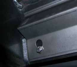
table of contents                               | 3

                          SAFETY LABEL                                                              OPERATING INSTRUCTIONS

Safety Label . .................................................................4     Some Safety Guidelines...............................................14
                                                                                      Wood Storage...............................................................15
                       UNIT DIMENSIONS                                                Ash Disposal.................................................................15
                                                                                      Fan Operation . ............................................................15
                                                                                      Creosote.......................................................................15
Unit Dimensions ............................................................5

                                                                                                                MAINTENANCE
                           INSTALLATION
                                                                                      Maintenance of Gold-Plated Doors..............................16
Before Installing Your Insert............................................6            Door Gasket.................................................................16
Chimney Specifications..................................................6             Door Latch Adjustment.................................................16
Wood Insert Specifications.............................................6              Glass Cleaning.............................................................16
Installing Your Insert.......................................................7        Glass Replacement......................................................16
Optional Flue Connector Kit...........................................7               Glass Removal.............................................................16
Masonry And Factory Built Fireplace Clearances .........8
How To Determine If Alternate
Floor Protection Materials Are Acceptable.....................8                                                    PARTS LIST
Flue Connector Bracket..................................................9
Installation Into a Masonry Fireplace..............................9                  Main Assembly & Options............................................17
Installation Into a Factory Built Fireplace........................9                  Faceplates ...................................................................18
Stainless Smoke Deflector Installation.........................10                     Brick Panels . ...............................................................19
Installation of the Faceplate and Trim...........................11
Installation of the Fan/blower........................................12                                           WARRANTY
Floor Protection............................................................13
Firebrick Assembly.......................................................13
Draft Control.................................................................13      Warranty ......................................................................20
Flue Baffle & Secondary Air Tube Installation..............13
Door Handle.................................................................13
Screen Door.................................................................13
First Fire.......................................................................14

 ALL PICTURES / DIAGRAMS SHOWN THROUGHOUT THIS MANUAL ARE FOR ILLUSTRATION PURPOSES ONLY.
 ACTUAL PRODUCT MAY VARY DUE TO PRODUCT ENHANCEMENTS.

                                                                                                                                        Regency I2404             |   3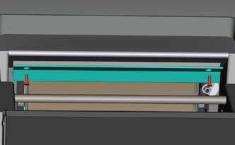
4
|
4 |
correct one.
Regency I2404
of the contents here for your review.
safety decal
SAFETY LABEL FOR I2404M
your Regency Insert. We have printed a copy
This is a copy of the label that accompanies
there is a difference, the label on the unit is the
improved. Check the label on the unit and if
NOTE: Regency units are constantly being
LISTED FACTORY BUILT FIREPLACE INSERT DO NOT REMOVE THIS LABEL MINIMUM CLEARANCES TO COMPONENTS REQUIRED FOR INSTALLATION: 5.5" (140mm) or 6" (152mm) STAINLESS STEEL LINER.
CERTIFIED FOR USE IN CANADA AND U.S.A. OPTIONAL COMPONENT: FAN (142-917), ELECTRICAL RATING: VOLTS 115, 60 HZ, 0.6 AMPS, SCREEN DOOR (846-102)
COMBUSTIBLE MATERIALS (MEASURED
MODEL: I2400M DANGER: RISK OF ELECTRIC SHOCK. DISCONNECT POWER BEFORE SERVICING UNIT. DO NOT ROUTE POWER CORD UNDER OR IN
CAUTION / ATTENTION Jan Feb Mar Apr May June
FROM INSERT BODY)
TESTED TO: ULC-S628-93 / UL-1482 / UL-737 FRONT OF APPLIANCE. DO NOT CONNECT THIS UNIT TO A CHIMNEY FLUE SERVICING ANOTHER APPLIANCE. DO NOT REMOVE BRICKS
OR MORTAR IN MASONRY FIREPLACE. FOR USE WITH SOLID WOOD FUEL ONLY. DO NOT USE GRATE OR ELEVATE FIRE. BUILD WOOD
REPORT NO.: 219-S-03-2 ADJACENT FIRE DIRECTLY ON HEARTH. RISK OF SMOKE AND FLAME SPILLAGE, OPERATE ONLY WITH DOORS FULLY OPEN OR FULLY CLOSED. IF
THE I2400M MEETS UL-737 STANDARD FOR FIREPLACE STOVES WHEN A FIRESCREEN IS PROVIDED. SIDEWALL A) 11 in / 280 mm 2017
INSTALLED IN A MOBILE HOME OPERATE ONLY WITH DOORS FULLY CLOSED - OPEN FEED DOOR TO FEED FIRE ONLY. WHEN OPER-
918-176e
MANTLE B) 20 in / 508 mm ATED WITH DOORS OPEN THE MANUFACTURER SUPPLIED SCREEN MUST BE USED. REPLACE GLASS ONLY WITH CERAMIC GLASS
INSTALL AND USE ONLY IN ACCORDANCE WITH THE MANUFACTURER'S INSTALLATION AND OPERATING INSTRUCTIONS. INSTALL AND USE ONLY IN MASONRY (5MM). INSPECT AND CLEAN CHIMNEY FREQUENTLY. UNDER CERTAIN CONDITIONS OF USE CREOSOTE BUILDUP MAY OCCUR RAP-
TOP FACING C) 12 in / 305 mm
FIREPLACE OR FACTORY BUILT FIREPLACE. CONTACT LOCAL BUILDING OR FIRE OFFICIALS ABOUT RESTRICTIONS AND INSTALLATION INSPECTION IN IDLY. DO NOT OVERFIRE, IF INSERT GLOWS YOU ARE OVER-FIRING. 2018
SIDE FACING D) 8 in / 200 mm
YOUR AREA.
246
INSTALLER ET UTILISER SELONS LES INSTRUCTIONS DU FABRICANT. INSTALLER ET UTILISER DANS UN FOYER DE MACONNERIE OU PRÉFABRIQUÉ. PIÈCES NÉCESSAIRES POUR INSTALLATION :5.5" (140MM) OR 6" (152MM) CONDUITS EN ACIER INOXYDABLE.
APPELER VOTRE INSPECTEUR DE BÂTIMENT OU LE DÉPARTMENT D’INCENDIE LOCAL POUR LES CODES LOCAUX ET POUR INSPECTÉE COMPOSANT FACULTATIF : VENTILATEUR (142-917); CARACTÉRISTIQUES ÉLECTRIQUES NOMINALES : 115 VOLTS, 60 HZ, 0,6 A, PARE- 2019
ÉTINCELLES (846-102)
DATE OF
VOTRE INSTALLATION ET FOYER. HOT WHILE IN OPERATION DO NOT TOUCH. KEEP CHILDREN,
SIGNATURE
DANGER : RISQUE DE CHOC ÉLECTRIQUE. DÉBRANCHER L’APPAREIL AVANT TOUTE RÉPARATION. NE PAS FAIRE PASSER LE FIL
Manufactured By:
ÉLECTRIQUE DEVANT L’APPAREIL NI EN DESSOUS. NE PAS RELIER CET APPAREIL À UNE CHEMINÉE DESTINÉE À L’ÉVACUATION D’UN CLOTHING AND FURNITURE AWAY. CONTACT MAY CAUSE
MANUFACTURE
INSTALL ONLY ON A NON-COMBUSTIBLE HEARTH RAISED (F) 0.5IN / 13MM ABOVE AN ADJACENT COMBUSTIBLE FLOOR. COMBUSTIBLE FLOOR MUST BE PROTECTED AUTRE APPAREIL. NE PAS ENLEVER DE BRIQUES NI DE MORTIER D’UNE CHEMINÉE DE MAÇONNERIE. N’UTILISER QUE DU COMBUS-
2020
SKIN BURNS. READ ABOVE INSTRUCTIONS.
BY NON-COMBUSTIBLE MATERIAL EXTENDING (E) 18 IN / 457 MM TO FRONT AND (G) 8 IN / 205 MM TO SIDES FROM FUEL DOOR. 0.5" FLOOR PROTECTION NEEDS TIBLE DE BOIS SOLIDE. NE PAS SURÉLEVER LES BÛCHES NI LES PLACER SUR DES GRILLES, MAIS LES DÉPOSER DIRECTEMENT
TO BE WITH k=0.84. SUR L’ÂTRE. RISQUE DE DÉGAGEMENT DE FUMÉE OU DE FLAMMES : TOUJOURS GARDER LES PORTES COMPLÈTEMENT OUVERTES
OU FERMÉES LORSQUE L’APPAREIL FONCTIONNE. DANS UNE MAISON MOBILE, TOUJOURS GARDER LES PORTES BIEN FERMÉES
2021
CHAUD LORS DE FONCTIONNEMENT.
6988 VENTURE ST., DELTA, BC V4G 1H4
LORSQUE L’APPAREIL FONCTIONNE. OUVRIR LA PORTE UNIQUEMENT POUR ALIMENTER LE FEU. SI LES PORTES DU POÊLE RESTENT
FIREPLACE PRODUCTS INTERNATIONAL LTD.
INSTALLER SUR UN ÂTRE DE MATÉRIAU NOM COMBUSTIBLE SURÉLEVÉ (F) 0,5 POUCES / 13MM-DESSUS DU PLANCHER COMBUSTIBLE ADJACENT. NE PAS TOUCHER. GARDEZ LES ENFANTS, VÊTEMENTS ET
(Duplicate Serial #)
OUVERTES, TOUJOURS UTILISER LE PARE-ÉTINCELLES FOURNI PAR LE FABRICANT. REMPLACER LA VITRE UNIQUEMENT PAR UNE
MADE IN CANADA
Serial No./ No de série
LE PLANCHER COMBUSTIBLE DOIT ÊTRE PROTÉGÉ PAR LE MATÉRIAU NOM COMBUSTIBLE QUI ÉTENDRE (E) 18 IN / 457MM À L’AVANT ET (G) 8 PO / 205 MM DE VITRE EN VITROCÉRAMIQUE (5 MM). INSPECTER ET NETTOYER FRÉQUEMMENT LA CHEMINÉE. SELON LE TYPE D’USAGE, LE CRÉO- MEUBLES AU LOIN. UN CONTACT AVEC LE PEAU PEUT July Aug Sept Oct Nov Dec
CHAQUE CÔTÉ DE LA PORTE. LE REVÊTEMENT DE PLANCHER DOIT AVOIR UNE ÉPAISSEUR DE 0,5 PO ET UN COEFFICIENT K DE 0,84. SOTE PEUT S’ACCUMULER RAPIDEMENT. NE PAS SURCHAUFFER; SI L’ENCASTRABLE SE MET À ROUGIR, IL SURCHAUFFE. OCCASIONER DES BRULURES.BRÛLURES CUTANÉES. LIRE
918-176g
246 CETTE ÉTIQUETTE.
Part #: 918-176g
Size: 3" H x 20-1/2" W (file at 100%)
Colour: Black on grey, except for what is indicated as being printed red on grey.
June 20/07: updated logo as per SCC requirements.
Mar. 1/10: Updated Logo
Apr. 7/11: Updated date of manufacture / added 5.5" liner
Oct. 3/13 Rev D - updated yr of manufacture
May 5/15: Rev. E - added French
May 2/16: Rev. F - updated yr of manufacture 2017-2021
Feb.14/17: Rev. G - moved serial #UNIT DIMENSIONS I2404M
dimensions | 5
5 95
Regency I2404 | 56 | installation
Regency Inserts are constructed with the high- CHIMNEY 7) Circulating air chambers (i.e. in a steel
est quality materials and assembled under strict fireplace liner or metal heat circulator) shall
quality control procedures that insure years of SPECIFICATIONS not be blocked.
trouble free and reliable performance.
Before installing, check and clean your chimney 8) Means must be provided for removal of the
It is important that you read this manual thor- system thoroughly. If in doubt about its condi- insert to clean the chimney flue.
oughly and fully understand the safe instal- tion, seek professional advice. Your Regency
lation and operating procedures. The more Insert is designed for installation into a masonry 9) Inserts that project in front of the fireplace
you understand the way your Regency Insert fireplace that is constructed in accordance with must be supplied with appropriate supporting
operates, the more enjoyment you will experi- the requirements of "The Standard for Chimneys, means.
ence from knowing that your unit is operating Fireplaces, Vents, and Solid Fuel Burning Ap-
at peak performance. pliance", N.F.P.A. 211, the National Building 10) Installer must mechanically attach the sup-
Code of Canada, or the applicable local code plied label to the inside of the firebox of the
requirements. fireplace into which the insert is installed.
BEFORE INSTALLING The appliance, when installed, must be electri-
YOUR INSERT "WARNING: This fireplace has been converted
cally grounded in accordance with local codes or,
for use with a wood insert only and cannot be
in the absence of local codes, with the National
1) Please read this entire manual before you used for burning wood or solid fuels unless
Electrical Code, ANSI/NFPA 70, or the Canadian
install and use your new wood insert. Failure all original parts have been replaced, and the
Electrical code, CSA C22.1.
to follow instructions may result in property fireplace re-approved by the authority having
damage, bodily injury or even death. Install jurisdiction."
Regency Inserts are designed to use either a
and use only in accordance with manufac- 5.5" (140mm) or 6" (152mm) flue.
turer’s installation and operating instructions. In order for a solid-fuel insert to be certified for use
Requirements for Installing in factory-built fireplaces, the above information
2) Check your local building codes - Building must be clearly stated in the installation manual
Inspection Department. You may require Solid-fuel Inserts in Factory-built
and appropriate markings. Final approval is
a permit before installing your insert. Be Fireplaces. contingent on the authority having jurisdiction.
aware that local codes and regulations may
override some items in the manual. 1) The insert must be tested and meet the
requirements of UL 1482 (U.S.) and or ULC
WARNING: Careless installation is the S628 (Canada) when tested in a masonry
major cause of safety hazard. Check all fireplace built per ULC S628. WOOD INSERT
local building and safety codes before
installation of unit. 2) The factory-built fireplace must be listed per
SPECIFICATIONS
UL 127 or ULC S610. Your fireplace opening requires the following
3) Notify your home insurance company that
minimum sizes:
you plan to install a fireplace insert or hearth 3) Clearances obtained from the masonry fire-
heater. place tests are also relevant for installation Height: 21.5"
in factory-built fireplaces. Width: 25"
4) Your fireplace insert is heavy and requires
Depth: 17"
two or more people to move it safely. The 4) Installation must include a full height listed
insert can be badly damaged by mishandling. chimney liner type HT requirements (2100 Two faceplates are available to seal the fireplace
degree F.) per UL 1777 (U.S.) or ULC opening:
5) If your existing fireplace damper control S635 (Canada). The liner must be securely
will become inaccessible once you have attached to the insert flue collar and the Standard Oversize
installed your Regency Insert, you should chimney top. 40" W x 30" H 48" W x 33" H
either remove or secure it in the open posi-
tion. 5) Means must be provided to prevent room
air passage to the chimney cavity of the
6) Inspect your fireplace and chimney prior fireplace. This may be accomplished by
to installing your insert to determine that it sealing the damper area around the chimney
is free from cracks, loose mortar or other liner, or sealing the fireplace front. Important:
signs of damage. If repairs are required,
they should be completed before installing 6) Alteration of the fireplace in any manner is The blower to this appliance must be turned
your insert. Do not remove bricks or mortar not permitted with the following exceptions; off anytime the fuel door is opened. Prior to
from your masonry fireplace. turning the blower back on, ensure there are no
a. external trim pieces which do not affect embers near the blower which may have fallen
7) Do not connect the insert to a chimney the operation of the fireplace may be onto the hearth when the fuel door was opened.
system servicing another appliance or removed providing they can be stored Once the fuel door is closed, the blower may
an air distribution duct. on or within the fireplace for re-assembly be turned back on.
if the insert is removed.
b. the chimney damper may be removed
to install the chimney liner.
Emissions from burning wood or gas could
contain chemicals known to the State of Cali-
fornia to cause cancer, birth defects or other
reproductive harm.
6 | Regency I2404installation | 7
INSTALLING YOUR OPTIONAL FLUE
INSERT CONNECTOR KIT
Your insert is very heavy and will require two The Straight Flue Adaptor (Part #846-504)
or three people to move it into position. The shown here, may be used to produce a secure
insert can be made a little lighter by removing connection between your flue connector and the
the cast iron door by opening it and lifting it insert collar. Detailed installation instructions are
off its hinges. Be sure to protect your hearth included with the kit.
extension with a heavy blanket or carpet scrap
during the installation.
Convection Grills
The convection grills are installed before the
unit is positioned inside the fireplace.
Position the grill on the inside bodyface side
and fasten using the bolts, washers and nuts
provided (2 per side) as shown in the diagrams.
View from Rear of Insert
Note: The grill has a front and rear, the holes
on the front side have rounded edges
and the rear holes have flat edges.
Regency I2404 | 78 | installation
MASONRY AND FACTORY BUILT FIREPLACE CLEARANCES
The minimum required clearances to combustible materials when installed into a masonry or factory built fireplace are listed below.
Unit Adjacent Mantle ** Top Side Minimum Minimum Minimum From Top of
Side Wall (to Top) Facing Facing Hearth Hearth Hearth Side Unit
(to Side) (to Top of Unit) (to Side of Unit) Extension* Thickness Extension*
A B C D E F G H
Medium 11"/280mm 20" (508mm) 12"(305mm) 8"(200mm) 18"(455mm) 1/2"(13mm) 8" (203mm) 20"(508mm)
Flush Insert
(I2404)
Side and Top facing is a maximum of 1.5" thick.
Floor protection must be non-combustible, insula-
tive material with an R value of 1.1 or greater.
* Hearth thickness of 0.5" with k value = 0.84",
r value = 0.6 or greater.
** A non-combustible mantel may be installed
at a lower height if the framing is made of
metal studs covered with a non-combustible
board.
** Max. mantle depth is 10" (254mm).
Thermal floor protection is not required if the unit is
raised 3.5" minimum (measured from the bottom of H
the stove). However, standard ember floor protec-
tion is required. It will need to be a non-combustible
material that covers 16" (406 mm) in the US and
18" (450 mm) in Canada to the front of the unit and
8" (200 mm) to the sides.
If the unit is not raised, thermal floor protection
required is 18" (450 mm) in the US and Canada.
Clearance diagram for Installations
All floor protection must be non-combustible (i.e.,
metals, brick, stone, mineral fiber boards, etc.) Any
organic materials (i.e. plastics, wood paper prod-
ucts, etc.) are combustible and must not be used. Minimum Hearth Extension for the front
The floor protection specified includes some form (E) and sides (G) are measured from the
of thermal designation such as R-value (thermal fuel door opening.
resistance) or k-factor (thermal conductivity).
HOW TO DETERMINE IF ALTERNATE
FLOOR PROTECTION MATERIALS ARE ACCEPTABLE
DEFINITIONS
The specified floor protector should be 3/8" Step (b):
Thermal Conductance:
(18mm) thick material with a K - factor of Calculate R of proposed system.
0.84. 4" brick of C = 1.25, therefore
Rbrick = 1/C = 1/1.25 = 0.80 C = Btu = W
1/8" mineral board of k = 0.29, therefore (hr)(ft2 )(oF) (m2))(K)
The proposed alternative is 4" (100mm) brick
with a C-factor of 1.25 over 1/8" (3mm) mineral Rmin.bd. = 1/0.29 x 0.125 = 0.431
Thermal Conductivity:
board with a K-factor of 0.29. Total R = Rbrick + Rmineral board =
0.8 + 0.431 = 1.231.
k = (Btu)(inch) = W = Btu
Step (a):
Step (c): (hr)(ft3)(oF) (m)(K) (hr)(ft)(oF)
Use formula above to convert specification
to R-value. Compare proposed system R of 1.231 to
Thermal Resistance:
R = 1/k x T = 1/0.84 x .75 = 0.893. specified R of 0.893. Since proposed system
R is greater than required, the system is
acceptable. R = (ft2)(hr)(oF) = (m2)(K)
Btu W
8 | Regency I2404installation | 9
FLUE CONNECTOR INSTALLATION INTO A
BRACKET FACTORY BUILT
Package contains: 3 brackets and 6 screws.
FIREPLACE
1) When installed in a factory built fireplace, a
These brackets are to be used to hold the flue
full stainless steel rigid or flexible flue liner is
liner (not supplied) to the Insert and keep the
mandatory, for both safety and performance
connection. The brackets are screwed into the
purposes. When a flue or liner is in use, the
top of the Insert in the pre-punched holes and
insert is able to breathe better by allowing
then screwed into the flue liner.
a greater draft to be created. The greater
draft can decrease problems such as, dif-
1) Positive Flue 2) Direct Flue ficult start-ups, smoking out the door, and
Connection Connection dirty glass.
with Cleanout with Cleanout
2) In order to position the flue liner, the exist-
ing rain cap must be removed from your
chimney system. In most cases the flue
damper should also be removed to allow
passage of the liner.
3) In most cases opening the existing spark
screens fully should give enough room for
the insert installation. If it does not, remove
and store.
4) If the floor of your fireplace is below the
level of the fireplace opening, adjust the
INSTALLATION INTO A insert's levelling bolts to accommodate the
MASONRY FIREPLACE difference. When additional shimming is
required, use non-combustible masonry or
The insert must be installed as per the require- 3a) Full Flue Liner steel shims.
ments of your local inspection authority. Three (No Cleanout Required)
methods of flue connection are acceptable in 5) Measure approximately the alignment of
most areas in the US, however a full flue liner the flue liner with the position of the smoke
required, by your inspector, to be installed outlet hole on the insert to check for pos-
is required in Canada.
when either the Positive flue con- sible offset. If an offset is required, use a
nection or Direct flue connection proper stainless steel unit available with the
1) Positive flue connection, where a large method is used. chimney liner.
blocking plate and a short connector pipe
is used. The use of one of the connection methods listed 6) Once the above items have been checked,
on this page not only increases the safety of your slide your insert into position after first po-
2) Direct flue connection, where a smaller insert by directing the hot gases up the flue, but sitioning the flue liner and offset if required.
blocking plate and a connector pipe to the will also help increase the unit's efficiency and (Re-install raincap at completion of installa-
first flue liner tile is used. decrease creosote deposits in the chimney. tion).
3) Full flue liner, where a stainless steel rigid When a connected flue or liner is in use, the NOTE: Refer to "Requirements for Installing
or flexible liner pipe is routed from the insert insert is able to “breathe” better by allowing a Solid-fuel Inserts in Factory-built Fire-
outlet collar to the top of the chimney. greater draft to be created. The greater draft can places" section for the requirements
decrease problems such as, difficult start-ups, for installing solid fuel inserts in factory
Regency highly recommends the use of a full smoking out the door, and dirty glass. built fireplaces.
liner as the safest installation and provides the
Prior to sliding your insert into its final position
most optimum performance. Your retailer should
and attaching the connector or liner pipe, the
be able to help you decide which system would
be the best for your application.
Note: A clean-out door is sometimes
Flush Inserts
Regency I2404 | 910 | installation
STAINLESS STEEL SMOKE DEFLECTOR INSTALLATION
The stainless smoke deflector is located in the upper front area of the firebox. The deflector is held in place with 2 bolts
Prior to the first fire, ensure deflector is seated properly and secured with 2 hand tightened bolts.
Smoke deflector installed with 2 bolts.
Note: This is a view from the back of the unit
Smoke deflector Smoke deflector is installed through the door
through the top.
opening in location shown in diagram
To replace the deflector, loosen off both bolts and slide defector upward and out. Install new defector and hand tighten bolts. Ensure positive location of
the defector prior to hand tightening.
WARNING: Operation of the unit with out proper installation of smoke deflector will void warranty.
Ensure defector is seated so bolts are situated
at the top of the keyhole before tightening.
10 | Regency I2404installation | 11
FACEPLATE AND TRIM INSTALLATION
Faceplate side panel plates must be installed Note: It may be easier to install the insula-
as follows: tion, faceplate top and faceplate trim
with the unit pulled slightly away from
the fireplace face. If this is done, be
1) Slide the spring nuts (supplied) over the very careful not to disturb the con-
slots in the insert’s side convection panels nector when shifting the unit to its
(the spring nuts may need to be squeezed final position.
with a pair of pliers first, to help them stay
in position). Now that your insert is installed, check once
more that all the clearances from the unit to
2) Screw the side faceplate panels, (item A in any combustible materials are correct as listed
the diagram) one to each side. earlier.
3) Using the top panel (item B in the diagram)
as a gauge, check that the side panels are
within approximately 1/4" of the overall width.
If the difference is greater than this, use the
supplied washers to attain the required width.
4) The unit may now be slid into final position
and attached to the connection system.
5) Once connection is made, the insulation strips
should be installed between the insert face-
plates and the fireplace face. The faceplate
top may now be installed (with insulation
strip behind) by aligning its brackets with the
top flange on the side shields and the angle
iron bar on the insert top. The faceplate trim
may be installed to the edge
of the faceplate at this time.
Faceplate Assembly
Regency I2404 | 1112 | installation
FAN/BLOWER INSTALLATION
Installer: Please record unit serial number here before installing blower.
Serial No.______________________________
Your fan should only be installed once the unit is 3) Ensure that the power cord is not in CAUTION: Label all wires prior
in place in order to prevent any damage to the contact with any hot stove surfaces. to disconnection when servic-
fan. To attach, follow the instructions provided
NOTE: DO NOT ROUTE POWER CORD
ing controls. Wiring errors can
with the fan. cause improper and dangerous
UNDER OR IN FRONT OF UNIT.
1) Align the fan support with the offset clip operation.
on the bottom of the ashlip. 4) Push the Regency logo plate into the two
holes in the front bottom left corner of the
2) Slide the supports into the clips. The tension fan. WARNING:
holding the clips in place may be adjusted by Electrical Grounding Instructions
increasing or decreasing the offset spacing Do not turn fan ON until your insert has This appliance is equipped with a
of the clips. reached operating temperature or at least
three pronged (grounding) plug for
30 minutes after starting fire.
your protection against shock hazard
and should be plugged directly into
a properly grounded three-prong
receptacle. Do not cut or remove the
grounding prong from this plug.
Grounding #8 Ground Lug
or
ns Ground wire
Se Lug Detail Nut
itch from fan
Sw Lockwasher
o
erm
Th Star washer
Nut
Star washer Ground wire
from power cord
Wire98gr.eps
updated Jan. 27/00
updated: Aug. 09/05
Neutral capitalized the word Nut
Green Manual/
Live Ground Auto Fan
120V AC Switch
Switch
60 Hz
White
Low (Red)
Fan Thermodisc
(normally open)
Black Black
High (Black)
Black
Fan Fan
Ground
Blower/Fan Wiring Diagram
12 | Regency I2404installation | 13
ensure the tube will not move when the unit DRAFT CONTROL
is burning. Though there are four air tubes
FLOOR PROTECTION in the medium units. Before establishing your first fire, it is important
Please check to ensure that your floor protection that your fully understand the operation of you
2) Slide the left baffle over the air tubes from draft control. The draft rod is on the left side of
and hearth will meet the standards for clearance
the front and then push it to the back. the Inserts and it controls the intensity of the
to combustibles. Your hearth extension must be
made from a non-combustible material. fire by increasing or decreasing the amount of
air allowed into the firebox. To increase your
draft - pull open, and to decrease - push closed.
FIREBRICK ASSEMBLY
Firebrick is included to extend the life of your
insert and radiate heat more evenly. Check to
see that all firebricks are in their correct posi-
tions and have not become misaligned during
shipping. Side View
Pull Open Push Closed
3) Tilt the left baffle up on top of the side chan- As well as a primary and glass wash air system,
nel and it will leave enough room to position the unit has a full secondary draft system that
the right baffle in the same manner as Step allows air to the induction ports at the top of the
1) above. Then reposition the left baffle flat firebox, just below the flue baffle.
on the air tubes.
WARNING: To build a fire in ignorance or
to disregard the information contained in
this section can cause serious permanent
damage to the unit and void your warranty.
SCREEN DOOR
Hook screen to the inside on the right side
of the firebox door opening. Lock in place by
Front View turning handle.
4) Important: push both baffles so they are
FLUE BAFFLE & tight against the side walls.
SECONDARY AIR TUBE
INSTALLATION
The flue baffle system located in the upper area
of the firebox is removable to make cleaning your
chimney system easier. The baffles must be
installed prior to your first fire. Smoke spill-
age and draft problems may occur if the Hooks Handle Lock
baffles are improperly positioned. Check Front View
the position of the baffles on a regular basis as Back Side of Screen Shown
they can be dislodged if too much fuel is forced
into the firebox.
NOTE: The handle must be positioned at 10
o'clock when closed to avoid the handle from
The unit arrives with the 2 baffle plates on the
DOOR HANDLE getting hot and to ensure the screen stays in
floor of the firebox. place.
Attach spring handle by rotating counter clock-
wise onto rod. Ensure that the rod fits into the
1) If all 4 air tubes are installed continue on
entire length of the spring handle.
to Step 2), if not, follow the instructions
below. Install the air tube into the holes in
the side channels. The notch goes on the
right hand side with the air holes facing
toward the door. Slide the tube into the left
hand side, as far as possible and then bring
it back into the hole on the right hand side.
Use a pair of vise grips or pliers and tap it
into place with a hammer. A tighter fit will
Handle at 10 o'clock position.
Regency I2404 | 1314 | operating instructions
13) Do not store any fuel closer than 2 feet from FIRST FIRE
SOME SAFETY your unit.
GUIDELINES When your installation is completed and in-
14) Do not burn salt drift wood as it will corrode spected, you are ready for your first fire.
1) Never use gasoline, gasoline type lantern your unit and void the warranty.
fuels, kerosene, charcoal lighter fuel, or
1) Open draft control fully.
similar liquids to start or ‘freshen up’ a fire 15) Do not operate the unit if the glass is broken
in your heater. Keep all such liquids well or missing. Do not operate the unit if the 2) Open firebox door and build a small fire using
away from the heater while it is in use. gasketing is worn out and not sealing the paper and dry kindling on the firebrick hearth,
door or the glass. wait a few minutes for a good updraft in the
2) Keep the door closed during operation and
flue to establish the fire. Leaving the door
maintain all seals in good condition. It is very important to carefully maintain your slightly open will help your fire start more
insert, including burning seasoned wood and rapidly.
3) Do not burn large quantities of paper in your maintaining a clean stove and chimney system.
insert. Have the chimney cleaned before the burning
season and as necessary during the season, as CAUTION: Never leave unit unat-
4) If you have smoke detectors, prevent smoke creosote deposits may build up rapidly. Moving tended if door is left open. This
spillage as this may set off a false alarm. parts of your insert require no lubrication. procedure is for fire start-up only,
as unit may over-heat if door is left
5) Do not overfire your insert. If the insert begin
to glow, you are overfiring. Stop adding open for too long.
WARNING
fuel and close the draft control. Overfiring Fireplace Stoves equipped with doors
can cause extensive damage to your stove 3) With the draft still in the fully open position,
should be operated only with doors fully add two or three seasoned logs to your fire.
including warpage and premature steel cor-
rosion. Overfiring will void your warranty. open or doors fully closed. If doors are Form a trench in the ash bed to allow air to
left partly open, gas and flame may be reach the rear of the firebox prior to closing
drawn out of the fireplace stove open- the door.
6) Do not permit creosote or soot buildup in the ing, creating risks from both fire and
chimney system. Check and clean chimney 4) After about 15 to 20 minutes, when your
smoke.
at regular intervals. wood has begun to burn strongly, adjust
your draft control down to keep the fire at a
7) Your Regency Insert can be very hot. You
When operated with doors open the moderate level.
may be seriously burned if you touch the manufacturer supplied screen must
insert while it is operating. Warn children be used. WARNING: Never build a roaring
of the burn hazard. fire in a cold stove. Always warm
8) The insert consumes air while operating, your stove up slowly!
provide adequate ventilation with an air
duct or open a window while the insert is in 5) Once a bed of coals has been established,
use. you may adjust the draft control to a low
setting to operate the unit in its most efficient
9) Do not use grates, irons or other methods mode.
for supporting fuel. Burn directly on the
bricks. 6) During the first couple of hours, keep the
combustion rate at a moderate level and
10) Open the draft control fully for 10 to 15 avoid a large fire until the paint is cured.
seconds prior to slowly opening the door Only then can you operate the insert at its
when refuelling the fire. maximum setting, and only after the metal
has been warmed.
11) Do not connect your unit to any air distribu-
tion duct. 7) For the first few hours, the insert will give off
an odor from the paint. This is to be expected
12) Your insert should burn dry, standard fire- as the high temperature paint becomes
wood only. The use of “mill ends” is discour- seasoned. Windows and/or doors should
aged as this fuel can easily overheat your be left open to provide adequate ventilation
insert. Evidence of excessive overheating while this temporary condition exists. Burn-
will void your warranty. As well, a large por- ing the insert at a very high temperature the
tion of sawmill waste is chemically treated first few times may damage the paint. Burn
lumber, which is illegal to burn in many areas. fires at a moderate level the first few days.
Chemically treated fire logs also must not
be burned in your insert. 8) Do not place anything on the insert top
during the curing process. This may result
in damage to your paint finish.
14 | Regency I2404operating instructions | 15
9) During the first few hours it may be more ASH DISPOSAL CREOSOTE
difficult to start the fire. As you dry out
your fire brick and your masonry flue (if During constant use, ashes should be removed When wood is burned slowly, it produces tar and
applicable), your draft will increase. every few days. Please take care to prevent the other organic vapors, which form creosote when
build-up of ash around the start-up air housing combined with moisture. The creosote vapors
10) For those units installed at higher elevations located inside the firebox, under the loading condense in the relatively cool chimney flue of a
or into sub-standard masonry fireplaces, door lip. slow-burning fire. As a result, creosote residue
drafting problems may occur. Consult an accumulates on the flue lining. When ignited, this
experienced dealer or mason on methods DO NOT ALLOW ASHES TO BUILD UP TO creosote can make an extremely hot fire.
of increasing your draft. THE LOADING DOORS.
11) Some cracking and popping noises may be Only remove ashes when the fire has died down.
experienced during the heating up process. Even then, expect to find a few hot embers. Removal for Cleaning
These noises will be minimal when your unit Always leave 1 to 2 inches of ash in the bottom
reaches temperature. of the firebox. This helps in easier starting and Removal of your insert for cleaning purposes
a more uniform burn of your fire. is usually not required if a proper installation
12) Before opening your door to reload, open
has been done. In the event that removal is re-
draft fully for approximately 10 to 15 seconds Ashes should be placed in a metal container with quired, be sure not to damage any parts needed
until fire has been re-established. This will a tight fitting lid. The closed container of ashes for re-installation. In most cases removal and
minimize any smoking. should be placed on a noncombustible floor or replacement of the baffle system should allow
on the ground, well away from all combustible full access for cleaning.
13) All fuel burning appliances consume oxygen materials, pending final disposal. If the ashes
during operation. It is important that you are disposed of by burial in soil or otherwise
supply a source of fresh air to your unit WARNING: Things to remember in case
locally dispersed, they should be retained in the
while burning. A slightly opened window is of chimney fire:
closed container until all cinders have thoroughly
sufficient for this purpose. cooled. Other waste should not be placed in the
ash container. 1) Close draft control
CAUTION: If the body of your unit 2) Call the Fire Department
starts to glow you are overfiring.
Stop loading fuel immediately and Ways to Prevent and
close the draft control until the glow FAN OPERATION Keep Unit Free of Creosote
has completely subsided.
The fan is to be operated only with the draft 1) Burn insert with draft control wide open for
14) Green or wet wood is not recommended for control rod pulled out at least 1/2" from the about 45 minutes every morning during burn-
your unit. If you must add wet or green fuel, fully closed position. The fan is not to be oper- ing season. This helps to prevent creosote
open the draft control fully until all moisture ated when the draft control rod is in the closed deposits within the heating system.
has been dispersed by the intense fire. position (pushed in). The fully closed position is
Once all moisture has been removed, the the low burn setting. 2) Burn insert with draft control wide open for
draft control may be adjusted to maintain about 10 - 15 minutes every time you add
the fire. The fan unit must not be turned on until a fire fresh wood. This allows the wood to achieve
has been burning for at least 30 minutes and the charcoal stage faster and burns up any
15) If you have been burning your insert on a the unit is hot enough. As well, after each fuel wood vapors which might otherwise be
low draft, use caution when opening the loading the fan must be shut off until 30 minutes deposited within the system.
door. After opening the damper, open the has elapsed.
door a crack, and allow the fire to adjust 3) Only burn seasoned wood! Do not burn
before fully opening the door. To operate fan automatically, push switch on wet or green wood. Seasoned wood that
side of fan housing to "Auto" and second switch has been dried at least one year must be
16) The controls of your unit should not be to either "High" or "Low" for fan speed. The used.
altered to increase firing for any reason. automatic temperature sensor will engage the
blower when the unit is at temperature and will 4) A small hot fire is preferable to a large
shut off the blower once the fire has gone out smouldering one that can deposit creosote
and the unit has cooled to below a useful heat within the system.
output range.
WOOD STORAGE 5) Check the chimney at least twice a month
To manually operate the fan system, push the during the burning season for creosote
Store wood under cover, such as in a shed, or first switch to "Man" and second switch to either build-up.
covered with a tarp, plastic, tar paper, sheets "high" or "Low". This will bypass the sensing
of scrap plywood etc., as uncovered wood can device and allow full control of the fan. Switching 6) Have chimney system and unit cleaned
absorb water from rain or snow, delaying the from "Auto" to "Manual" or "High" to "Low" may by competent chimney sweeps twice a
seasoning process. be done at any time. year during the first year of use and at
least once a year thereafter or when a
significant layer of creosote has accu-
mulated (3mm / 1/8" or more) it should be
removed to reduce the risk of a chimney
fire.
Regency I2404 | 1516 | maintenance
DOOR GASKET GLASS CLEANING
If the door gasket requires replacement, 7/8"
Only clean your glass window when it is cool.
diameter material must be used. A proper high
Your local retailer can supply you with special
temperature gasket adhesive is required. A
glass cleaner if plain water and a soft cloth does
gasket repair kit, Part # 846-570 is available
not remove all deposits.
from your local Regency dealer.
DOOR LATCH GLASS REPLACEMENT
ADJUSTMENT Your Regency Insert is supplied with 5 mm.
Neoceram ceramic glass (Part #846-304) that
The door latch may require adjustment as the will withstand the highest heat that your unit will
door gasket material compresses after a few produce. In the event that you break your glass
fires. Removal of the spacer washer, shown by impact - purchase your replacement from an
in the diagram below, will allow the latch to authorized Regency dealer only, and follow our
be moved closer to the door frame, causing step-by-step instructions.
a tighter seal. Remove and replace the nuts,
washer as shown.
GLASS REMOVAL
Allow the stove to cool before removing or re-
placing glass. Remove the door from the insert
and remove the glass retainer. Use caution
when removing broken glass to prevent injury.
When placing the replacement glass in the
door, make sure that the glass gasketing will
properly seal your unit. Replace the retainer
and tighten securely, but do not wrench down
on the glass as this may cause breakage. Do
not substitute materials. If your glass door does
break, do not continue to use your unit until it
has been replaced.
Avoid impact on glass doors such
as striking or slamming shut.
16 | Regency I2404parts list | 17
MAIN ASSEMBLY & OPTIONS - I2404M
Part # Description Part # Description Part # Description
1) 850-152 Door Assy - Large Gold 142-917 Fan Assembly 42) 163-932 Convection Grill - Gold (Opt)
850-151 Door Assy - Large Black 24) 910-157/P Fan Motor 120 Volts 163-930 Convection Grill - Blk (Opt)
850-153 Door Assy - Large Nickel Accent 25) 910-678 Power Cord 120 Volts 43) * Hex Nut 10-24 Zinc Coated
850-154 Door Assy - Large Gold Accent 27) 910-142 Fan Thermodisc 44) * Washer #10 Flat
28) 910-140 Fan Speed Hi / OFF / Low 45) * Bolt, 10-24 x 3/4"
2) 846-304 Glass - Replacement Switch (3-way) Blk Carriage
4) 936-243 7/8" Adhesive Tape Gasket 29) 910-138 Auto / Manual On /
5) 846-920 Glass Retainer Clips (8/set) OFF Switch 47) 846-102 Screen Door
6) * Screw 1/4-20 x 3/8" 30) * Grommet Strain Relief 948-223 Regency Logo - Nickel
7) 948-172/P Glass Retainer - Large 36) 033-953 Air Tube 3/4" (Qty:4) (each) 948-216 Regency Logo - Gold
9) 846-973 Door Handle Assembly 37) 020-957 Baffle (2/set) 48) 820-482 Stainless smoke deflector
918-993 Manual
16) 846-570 Door Gasket Kit
17) 846-918 Hinge Caps - Gold Plated *Not available as a replacement part.
(2/set)
948-079 Hinge Caps - Nickel (each)
19) 948-101 Spring Handle - Large Gold
20) 948-102 Spring Handle - Small Gold
948-135 Spring Handle - Large Nickel
948-136 Spring Handle - Small Nickel
23) 846-235 Flue Brackets Package
48
Regency I2404 | 1718 | parts list
FACEPLATES - I2404M
Part # Description
140-911 Faceplate & Trim Set - Regular
180-570 Black Trim Regular (set of 3)
285) * Trim Right Regular
286) * Trim Top Regular
287) * Trim Left Regular
288) * Faceplate Side Regular
289) * Faceplate Top Regular
140-913 Faceplate & Trim Set - Oversize
180-572 Black Trim Oversize (set of 3)
295) * Trim Right Oversize
296) * Trim Top Oversize
297) * Trim Left Oversize
298) * Faceplate Side Oversize
299) * Faceplate Top Oversize
*Not available as a replacement part.
296
286
295
299 285
298 289
288
297
298 287
288
OVERSIZE
REGULAR
18 | Regency I2404parts list | 19
BRICK PANELS - I2404M
Part # Description
180-960 Firebrick - Complete Set
70) 902-111 Brick Regular Full Size: 1-1/4" x 4-1/2" x 9"
75) * Brick Partial: 1-1/4 x 4-1/2" x 2"
76) * Brick Partial: 1-1/4" x 2" x 9"
Regency I2404 | 1920 | warranty
Limited Lifetime Warranty
FPI Fireplace Products International Ltd. (for Canadian customers) and Fireplace Products U.S., Inc. (for U.S.
customers) (collectively referred to herein as “FPI”) extends this Limited Lifetime Warranty to the original
purchaser of this appliance provided the product remains in the original place of installation. The items covered by
this limited warranty and the period of such coverage is set forth in the table below.
Some conditions apply (see below).
The policy is not transferable, amendable or negotiable under any circumstances.
Labor
Wood Products
Component Coverage Coverage
5 2 1
Components Covered Lifetime Warranty (Years)
years years year
Welded Firebox Steel 5
All Stainless Steel Components, Smoke Deflectors,
3
Heat Shields etc.
Air Tubes 3
Airmate 3
Door handle and latch assembly, all hardware 3
Glass Thermal Breakage Only 3
Steel Faceplates, Accessory Housings 3
All Plating 3
Ash Drawer, Heatshields, Pedestal
All Baffles, Steel, Ceramic, Vermiculite
All castings, firebox, surrounds, doors, panels etc. 3
All Electrical, Blower, wiring, switches etc. 2
Glass - Crazing 1
Catalyst Assembly 6 Years
3
Prorated
Venting/Chimney 1
Screens 1
Conditions:
Warranty protects against defect in manufacture or FPI factory assembled components only, unless herein
specified otherwise.
Any part(s) found to be defective during the warranty period as outlined above will be repaired or replaced at FPI’s
option through an accredited distributor, dealer or pre-approved and assigned agent provided that the defective
part is returned to the distributor, dealer or agent for inspection if requested by FPI. Alternatively, FPI may at its
own discretion fully discharge all of its obligations under the warranty by refunding the verified purchase price of
the product to the original purchaser. The purchase price must be confirmed by the original Bill of Sale.
The authorized selling dealer, or an alternative authorized FPI dealer if pre-approved by FPI, is responsible for all
in-field diagnosis and service work related to all warranty claims. FPI is not responsible for results or costs of
workmanship of unauthorized FPI dealers or agents in the negligence of their service work.
At all times FPI reserves the right to inspect reported complaints on location in the field claimed to be defective
prior to processing or authorizing of any claim. Failure to allow this upon request will void the warranty.
Revision Date: December 2016 Regency Wood Products Warranty
20 | Regency I2404warranty | 21
All warranty claims must be submitted by the dealer servicing the claim, including a copy of the Bill of Sale (proof
of purchase by you). All claims must be complete and provide full details as requested by FPI to receive
consideration for evaluation. Incomplete claims may be rejected.
Replacement units are limited to one per warranty term. Airtube and baffle replacements are limited to one
replacement per term.
Unit must be installed according to all manufacturers’ instructions as per the manual.
All Local and National required codes must be met.
The installer is responsible to ensure the unit is operating as designed at the time of installation.
The original purchaser is responsible for annual maintenance of the unit, as outlined in the owner’s manual. As
outlined below, the warranty may be voided due to problems caused by lack of maintenance.
Repair/replacement parts purchased by the consumer from FPI after the original coverage has expired on the unit
will carry a 90 day warranty, valid with a receipt only. Any item shown to be defective will be repaired or replaced
at our discretion. No labor coverage is included with these parts
Exclusions:
This Limited Lifetime Warranty does not extend to paint, rust or corrosion of any kind due to a lack of maintenance
or improper venting, combustion air provision, corrosive chemicals (i.e. chlorine, salt, air, etc.), firebrick (rear, sides
or bottom), door or glass gasketing, or any other additional factory fitted gasketing.
Malfunction, damage or performance based issues as a result of environmental conditions, location, chemical
damages, downdrafts, installation error, installation by an unqualified installer, incorrect chimney components
(including but not limited to cap size or type), operator error, abuse, misuse, use of improper fuels (such as
unseasoned cordwood, mill-ends, construction lumber or debris, off-cuts, treated or painted lumber, metal or foil,
plastics, garbage, solvents, cardboard, coal or coal products, oil based products, waxed cartons, compressed pre-
manufactured logs), lack of regular maintenance and upkeep, acts of God, weather related problems from
hurricanes, tornados, earthquakes, floods, lightning strikes/bolts or acts of terrorism or war, which result in
malfunction of the appliance are not covered under the terms of this Limited Lifetime Warranty.
FPI has no obligation to enhance or modify any unit once manufactured (i.e. as products evolve, field modifications
or upgrades will not be performed on existing appliances).
This warranty does not cover dealer travel costs for diagnostic or service work. All labor rates paid to authorized
dealers are subsidized, pre-determined rates. Dealers may charge homeowner for travel and additional time
beyond their subsidy.
Any unit showing signs of neglect or misuse will not be covered under the terms of this warranty policy and may
void this warranty. This includes units with rusted or corroded fireboxes which have not been reported as rusted or
corroded within three (3) months of installation/purchase.
Units which show evidence of being operated while damaged, or with problems known to the purchaser and
causing further damages will void this warranty.
Units where the serial no. has been altered, deleted, removed or made illegible will void this warranty.
Minor movement, expansion and contraction of the steel is normal and is not covered under the terms of this
warranty.
Freight damages for products or parts are not covered under the terms of the warranty.
Products made or provided by other manufacturers and used in conjunction with the FPI appliance without prior
authorization from FPI may void this warranty.
Revision Date: December 2016 Regency Wood Products Warranty
Regency I2404 | 2122 | warranty
Limitations of Liability:
The original purchaser’s exclusive remedy under this warranty, and FPI’s sole obligation under this warranty,
express or implied, in contract or in tort, shall be limited to replacement, repair, or refund, as outlined above. IN
NO EVENT WILL FPI BE LIABLE UNDER THIS WARRANTY FOR ANY INCIDENTAL OR CONSEQUENTIAL COMMERCIAL
DAMAGES OR DAMAGES TO PROPERTY. TO THE EXTENT PERMITTED BY APPLICABLE LAW, FPI MAKES NO EXPRESS
WARRANTIES OTHER THAN THE WARRANTY SPECIFIED HEREIN. THE DURATION OF ANY IMPLIED WARRANTY IS
LIMITED TO DURATION OF THE EXPRESSED WARRANTY SPECIFIED ABOVE. IF IMPLIED WARRANTIES CANNOT BE
DISCLAIMED, THEN SUCH WARRANTIES ARE LIMITED IN DURATION TO THE DURATION OF THIS WARRANTY.
Some U.S. states do not allow limitations on how long an implied warranty lasts, or allow exclusion or limitation of
incidental or consequential damages, so the above limitations or exclusions may not apply to you.
Customers located outside the U.S. should consult their local, provincial or national legal codes for additional
terms which may be applicable to this warranty.
How to Obtain Warranty Service:
Customers should contact the authorized selling dealer to obtain warranty service. In the event the authorized
selling dealer is unable to provide warranty service, please contact FPI by mail at the address listed below. Please
include a brief description of the problem and your address, email and telephone contact information. A
representative will contact you to make arrangements for an inspection and/or warranty service.
Canadian Warrantor: U.S. Warrantor:
FPI Fireplace Products International Ltd. Fireplace Products U.S., Inc.
6988 Venture St. PO Box 2189 PMB 125
Delta, British Columbia Blaine, WA
Canada, V4G 1H4 United States, 98231
Or contact the Regency Customer Care Centre at 1-800-442-7432 (phone) / 604-946-4349 (fax)
Product Registration and Customer Support:
Thank you for choosing a Regency Fireplace. Regency strives to be a world leader in the design, manufacture, and
marketing of hearth products. To provide the best support for your product, we request that you complete a
product registration form at http://www.regency-fire.com/Customer-Care/Warranty-Registration.aspx within
ninety (90) days of purchase.
22 | Regency
Revision Date:I2404
December 2016 Regency Wood Products Warrantywarranty | 23
Product Registration and Customer Support:
Thank you for choosing a Regency Fireplace. Regency strives to be a world leader in the design, manufacture, and
marketing of hearth products. To provide the best support for your product, we request that you complete a product
registration form found on our Web Site under Customer Care within ninety (90) days of purchase.
For purchases made in CANADA or the UNITED STATES:
http://www.regency-fire.com/Customer-Care/Warranty-Registration.aspx
For purchases made in AUSTRALIA:
http://www.regency-fire.com.au/Customer-Care/Warranty-Registration.aspx
You may also complete the warranty registration form below to register your Regency Fireplace Product and mail and/or
fax it back to us, and we will register the warranty for you. It is important you provide us with all the information below in
order for us to serve you better.
Warranty Registration Form (or Register online immediately at the above Web Site):
Warranty Details
Serial Number (required):
Purchase Date (required) (mm/dd/yyyy):
Product Details
Product Model (required):
Dealer Details
Dealer Name (required):
Dealer Address:
Dealer Phone #:
Installer:
Date Installed (mm/dd/yyyy):
Your Contact Details (required)
Name:
Address:
Phone:
Email:
For purchases made in CANADA: For purchases made in the UNITED STATES: For purchases made in AUSTRALIA:
FPI Fireplace Products Fireplace Products U.S., Inc. Fireplace Products Australia Pty
International Ltd. PO Box 2189 PMB 125 Ltd
6988 Venture St. Blaine, WA 1- 3 Conquest Way
Delta, British Columbia United States, 98231 Hallam, VIC
Canada, V4G 1H4 Australia, 3803
Phone: 604-946-5155 Phone: 604-946-5155 Phone: +61 3 9799 7277
Fax: 604-946-4349 Fax: 604-946-4349 Fax: +61 3 9799 7822
For fireplace care and tips and answers to most common questions please visit our Customer Care section on our Web Site.
Please feel free to contact your selling dealer if you have any questions about your Regency product.
Regency I2404 | 23You can also read