ENG/FR Woodburning SE models - OPERATION AND INSTALLATION MANUAL - Heat Design
←
→
Page content transcription
If your browser does not render page correctly, please read the page content below
ENG/FR

OPERATION AND INSTALLATION MANUAL
Woodburning SE models
Guide d’utilisation et Mode d'Emploi

Christon 550
Christon 750
December 2019
Contents
PAGE ITEM
2-15 Operation and installation manual                                                                 ENG
      How to? Exploded parts diagrams
16-25 Pièces détachées, vue éclatées, assemblage                                                       ENG/FR

26-37                 Guide d’utilisation et Mode d'Emploi                                             FR
38-39                 Certificate - EN Test

            INSTALLATION MANUAL AND OPERATING INSTRUCTIONS
                     CHRISTON 550                                                  CHRISTON 750

This manual refers to the stoves listed above, which are tested in accordance with EN 13240.

Thank you for purchasing your new stove from Mendip Stoves. Please read this manual carefully to ensure that you
get maximum enjoyment and performance from your new stove and to prevent any potential operational problems.
Please note that “all local regulations, including those referring to national and European Standards, need to be
complied with when installing this appliance”. For further information on installing and using fireplaces and wood
burning stoves, please see the relevant building regulations that apply to the country in which your stove is installed
and tested. These instructions cover the basic principals to ensure the satisfactory installation of your stove, although
detail may need slight modification to suit particular local site conditions.

                                                    HEIGHT            WIDTH              DEPTH            WEIGHT
 CHRISTON 550                                       550 mm            550 mm            360 mm             81 kg
 CHRISTON 550 INSET                                 550 mm            550 mm            360mm              91 kg
 CHRISTON 550 LOGSTORE                              800 mm            550 mm            360 mm
 CHRISTON 550 SIDE TABLE (ONLY)                     300 mm            550 mm            360 mm             15 kg
 CHRISTON 750                                       550 mm            750 mm            360 mm             110 kg
 CHRISTON 750 INSET                                 550 mm            750 mm            360mm              120 kg
 CHRISTON 750 LOGSTORE                              800 mm            750 mm            360 mm
 CHRISTON 750 SIDE TABLE (ONLY)                     300 mm            750 mm            360 mm              20 kg

                                                            2 of 40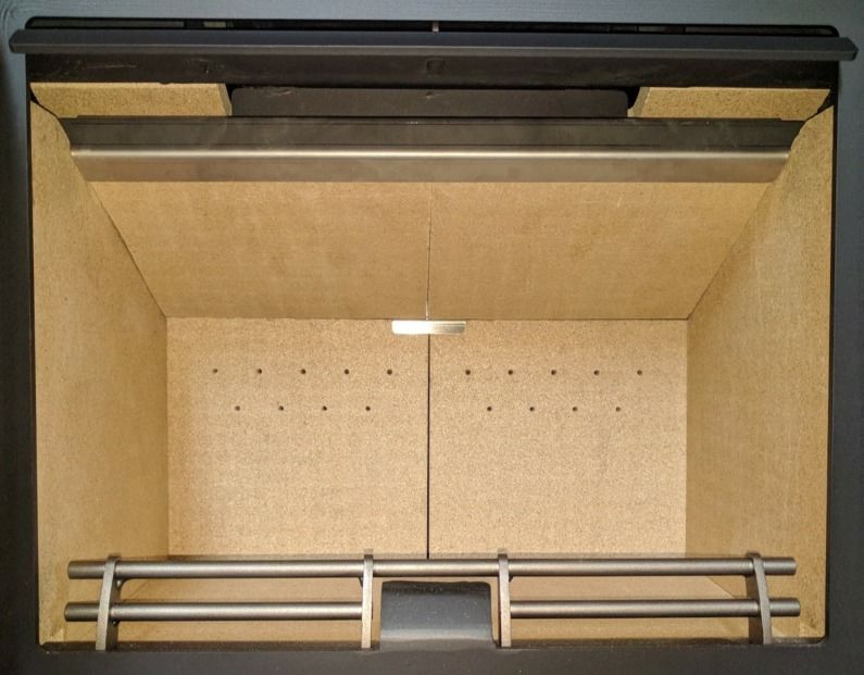
HEALTH AND SAFETY PRECAUTIONS
—----------------------------------------------------------------------------------------------------------------------------------------------------------------
INFORMATION FOR THE USER, INSTALLER AND SERVICE ENGINEER
—----------------------------------------------------------------------------------------------------------------------------------------------------------------
Special care must be taken when installing a stove such that the requirements of the Health & Safety at Work Act are met.

Handling
Adequate facilities must be available for loading, unloading and site handling.

Fire Cement
Some types of fire cement are caustic and should not be allowed to come into contact with the skin. In case of contact wash
immediately with plenty of water.

PREPARATORY WORK AND SAFETY CHECKS

IMPORTANT WARNING
This stove must not be installed into a chimney that serves any other heating appliance. There must not be an extractor fan
fitted in the same room as the stove because this can cause the stove to emit fumes into the room.

Asbestos
This stove contains no asbestos. If there is a possibility of disturbing any asbestos in the course of installation then please
seek specialist guidance and use appropriate protective equipment.

Metal Parts
When installing or servicing this stove care should be taken to avoid the possibility of personal injury.

CO Alarms:-
Building regulations require that whenever a new or replacement fixed solid fuel or wood/biomass appliance is installed in
a dwelling a carbon monoxide alarm must be fitted in the same room as the appliance. Further guidance on the installation
of the carbon monoxide alarm is available in BS EN 50292:2002 and from the alarm manufacturer’s instructions.

Provision of an alarm must not be considered a substitute for either installing the appliance correctly or ensuring regular
servicing and maintenance of the appliance and chimney system.

Stove paint Aerosols
Paint aerosols are flammable and therefore dangerous to use around a lit stove. Be sure to allow aerosols spray paints
to dry and ventilate the room well before lighting the stove. The use of any aerosol around lit stove is dangerous and
care must be taken handling aerosols.

                                                IMPORTANT:
These instructions cover the basic principles to ensure the satisfactory installation of Mendip Stoves
product :- Christon models, although detail may need slight modification to suit particular local site
conditions.
In all cases the installation must comply with current Building Regulations, Local Authority Byelaws and
other specifications or regulations as they affect the installation of the stove. It should be noted that the
Building Regulations requirements may be met by adopting the relevant recommendations given in British
Standards BS 8303, BS EN 15287 as an alternative means to achieve an equivalent level of performance to
that obtained following the guidance given in Approved Document J.

Fireguards

The use a fireguard to BS 8423:2002 in the presence of children, aged and/or infirm persons is essential for
their safety, even when the stove is not in use. The glass on the stove is ceramic glass and able to withstand
very high temperatures however it is not toughened and a hard impact could cause the glass to break.

                                                                                3 of 40
FLUE & CHIMNEY CONNECTION TO STOVE
The outlet from the chimney should be above the roof of the building in accordance with the provisions of Building
Regulations Approved Document J. If installation is into an existing chimney then it must be sound and have no cracks or
other faults which might allow fumes into the house. Older properties, especially, may have chimney faults or the cross
section may be too large .
Mendip Stoves recommend the use of a solid fuel flue lining system for all installation into existing chimneys. All chimney
systems must be used in accordance with Building Regulations Approved Document J.
If an existing chimney is used the chimney must be clear of obstruction and be swept clean immediately before installation
of the stove. The chimney should be tested to confirm the chimney will provide the correct chimney pressure for the stove.
If the stove is fitted in place of an open fire the chimney should be swept one month after installation to clear any soot falls
which may have occurred due to the difference in combustion between the stove and the open fire. If there is no existing
chimney then either a prefabricated block chimney in accordance with Building Regulations Approved Document J or a twin
walled insulated stainless steel flue to BS 1856-1 . These chimneys must be fitted in accordance with the manufacturer’s
instructions and Building Regulations. A single wall metal flue pipe is suitable for connecting the stove to the chimney but
is not suitable for using for the complete chimney. The chimney and connecting flue pipe must have a minimum diameter
of 125 mm and its dimension should be not less than the size of the outlet socket of the stove. Registered smoke exempt
models burning wood only can be installed on flue of 125mm throughout.. Any bend in the chimney or connecting flue
pipe should not exceed 45�. 90� bends should not be used other than within 150 mm of stove rear flue outlet.

 Chimney Connection
 In order for the stove to perform satisfactorily the chimney height must be sufficient to ensure an adequate draught
 to clear the products of combustion and prevent smoke problems into the room.

 Tested Gas flow rates flue                 Flue gas flow rate      Test flue gas temperature
 gas temperatures                                                                                  @ pascals of pressure
                                                        Wood                            wood
 Christon 550                               5.7 g/s                          220 °C                         12 pa.
 Christon 750                               7.6 g/s                          274 °C                         12 pa.

A chimney height of not less than 4.5 metres measured vertically from the outlet of the stove to the top of the chimney
should be satisfactory. Alternatively the calculation procedure given in BS5854:1980 may be used as the basis for deciding
whether a particular chimney design will provide sufficient draught.
If it is found that there is excessive draught in the chimney then either an adjustable flue damper or alternately a draught
stabiliser should be fitted. The adjustable flue damper should not close off the flue entirely but should in its closed position
leave a minimum continuous opening free area of at least 20 % of the total cross sectional area of the flue or flue pipe.
Adequate provision e.g. easily accessible soot door or doors must be provided for sweeping the chimney and connecting flue
pipe.
Your appliance needs to be maintained routinely, the throat plate/baffle should be cleaned regularly (monthly) . The flue
 pipe can be cleaned using a flexible brush. Only Use a dry cloth on external surfaces. Over time the glass may become dirty,
 clean with a damp cloth and polish off with damp cloth. If the stove has not been used for some time the flue should be
 checked for blockages before use. Do not modify the appliance; only use spares authorised by the manufacturer.

  DISTANCE TO COMBUSTIBLE MATERIALS
Combustible materials should not be located where the heat dissipating through the walls of fireplaces or flues could ignite
it. Therefore when installing the stove in the presence of combustible materials due account must be taken of the guidance
on the separation of combustible material given in Building Regulations Approved Document J and also in these stove
instructions. The minimum distances to flammable materials are specified on the EN 13240 plate on the back of the stove.

                             Distance to       Distance to    Distance to combustibles             Suitable for 12mm non-
                          combustibles rear combustbles sides sides Convection models              combustible floor plate
Christon 550                  200 mm            200 mm                  N/A                                   YES
Christon 750                  100 mm            100 mm                  N/A                                   YES

                                                                 4 of 40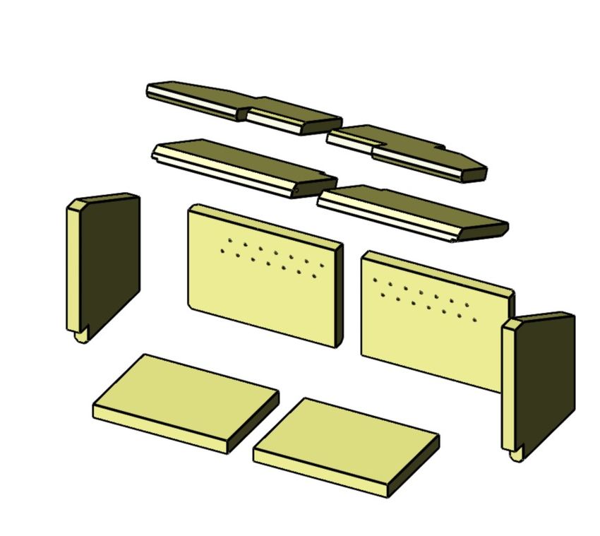
STOVE PERFORMANCE & TESTING
Christon 550 and 750 models are tested in accordance with EN 13240/13229. The Christon 550 & 750 have been
recommended as suitable for use in smoke control areas when burning wood logs and when fitted with a mechanical stop
to prevent closure of the secondary/tertiary air control. Christon 550 0 cm / 0% and Christon 750 2.5 cm or 50% open

                     Nominal        Efficiency     CO @   Dust   DEFRA Smoke Mechanical SE Secondary Air SE
                    Heat Output                   13% O₂ mg/m₀ ³    Exempt      Air Stop    Requirements
CHRISTON 550          4.8 kW          77.8 %        0.09   30    Yes / SE model   NO            N/A
CHRISTON 750           8.7 kW         78.4 %        0.09        32     Yes / SE model        YES          50 % / 2.5 cm

                                                 Log Length                               Wood Reload      Wood Reload
                      Max Length       SE Dimensions L x W x D       Number of Logs         Interval         Weight
CHRISTON 550             40 cm             25 x 11 x 11 cm                   1              45 min            1.0 kg
CHRISTON 750             60 cm             25 x 14 x 11 cm                   2              50 min            1.6kg

  STOVE DIMENSIONS AND CONNECTION MEASUREMENTS
                          D                                                                        E

                                                           A                                                  F

                                                                                                                       H
                          B
                                                                                        C

                                                        DISTANCE FROM
                                                       Collar
                                              Stove Rear    Floor to  Floor to Air Intake
                      HEIGHT WIDTH DEPTH                Size
                                               to Centre Rear Flue Centre Air Diameter
                                              Flue Collar    Stove     Intake
                         A     B     C    D        E           F         H*
CHRISTON 550          550mm 550mm 360mm 125mm 105mm           N/A      50mm     80mm
CHRISTON 550          800mm 550mm 360mm 125mm                        105mm          N/A            300mm        80mm
LOGSTORE
CHRISTON 750          550mm 750mm 360mm 150mm                        105mm          N/A            50mm         80mm
CHRISTON 750          800mm 750mm 360mm 150mm                        105mm          N/A            300mm        80mm
LOGSTORE
      * When the adjustable legs are fully extended, the centre of the air intake (H) is 60mm away from the floor.

                                                           5 of 40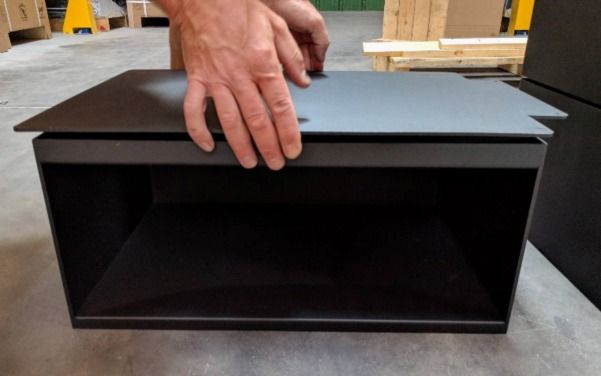
STOVE DIMENSIONS AND CONNECTION MEASUREMENTS
                                                              745
Christon 750                                                                                                                    355
                                                               154

               550

                                                                                     10 -20
                                                               80

                                           372,5
                      105

                                                                      5

                                   112,5
                                                                     12
                                               12
                                                    5

                                                       550                                                    105

Christon 550                                                                                                                         136
                                                   E

                                                                                                                                           26
                                                                                                                16,
                                                                                                                    7

                                                                                                                                       5
                                                                                                                                 22,
                                                                                                                        115°
                                                                                                   550

                                                                                                                               256
                     550

                                                                                                                                     198
                                                                                              80
                            10

                                                                                                                10

                                                                                                         52
                                                   E

                                                        550

                                            275
                                     75                               75
                                                                               105
                             105

                                             105
                                            11025
                                               0

                                                                     6 of 40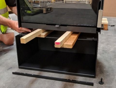
DISTANCE TO NON COMBUSTIBLE MATERIALS

The stove can be recessed in a suitable sized non - combustible fireplace but a permanent free air gap of at least 50mm
must be left around the sides and top and at least 50mm at the back of the stove to obtain reasonable heat output and for
access to the stove for removal and maintenance. A clearance of 100mm will give a better heat output.

All non - combustible walls closer than 100mm to the stove should be at least 75mm thick. For practical reasons the back
wall of the fireplace recess and the hearth should ideally be made of non -combustible material. When installing a your stove
in a non combustible chamber combustible materials should not be located where the heat dissipating through the walls of
fireplaces or flues could ignite it. Therefore when installing the stove in the presence of combustible materials due account
must be taken of the guidance on the separation of combustible material given in Building Regulations Approved Document
J and also in these stove instructions. The minimum distances to flammable materials are specified on the EN 13240 plate
on the back of the stove

  HEARTH

The hearth should be able to accommodate the weight of the stove and its chimney if the chimney is not independently
supported. Christon 550 & 750 stoves have been tested and are suitable to be installed on a 12 mm non combustible plate
such as 12 mm glass plates . Installation of all hearths should comply in size and construction so that it is in accordance with
the provisions of the current Building Regulations Approved Document J.
The clearance distances to combustible material beneath, surrounding or on the hearth and walls adjacent to the hearth
should comply with the guidance on the separation of combustible material given in Building Regulations Approved Document
J and also in these stove instructions.
If the stove is to be installed on a wooden floor, it must be covered with a non-combustible material at least 12 mm thick,
in accordance with Building Regulations Approved Document J, to a distance of 30 cm in front of the stove and 15 cm to
each side measuring from the door of the combustion chamber.

  COMBUSTION AIR
In order for the stove to perform efficiently and safely there should be an adequate air supply into the room in which the
stove is installed to provide combustion air. This is particularly necessary if the room is double-glazed or a flue draught
stabiliser is operating in the same room as the appliance. The provision of air supply to the stove must be in accordance with
current Building Regulations Approved Document J. An opening window is not appropriate for this purpose. Air inlets must
be positioned in such a way that they cannot be blocked. An air inlet may be a vent (the vent must be open and the capacity
for the vent sufficient when the stove is lit) .

There are no European rules regarding the minimum distance to non-flammable walls, Mendip Stoves recommend leaving
a gap of at least 50mm behind and to sides of stove.

Christon 550 & 750 models take all combustion from a single 80mm port under the stove, with the door closed the air port
supplies all combustion air for the appliance. This can be connected to the outside via a 80mm pipe so the appliance does
not draw air from the room. However Mendip stoves still recommends the use of an air brick as laid out in document j for
when the stove is being reloaded.

 COMMISSIONING AND HANDOVER
Ensure loose parts ( brick and grates) are fitted in accordance with the instructions given in the instruction booklet. On
completion of the installation allow a suitable period of time for any fire cement and mortar to dry out, a small fire may be
lit to check that smoke and fumes are taken from the stove up the chimney and emitted safely into the atmosphere. Do not
run at full output for at least 24 hours.
On completion of the installation and commissioning ensure that the operating instructions for the stove are left with the
customer. Ensure to advise the customer on the correct use of the appliance with the fuels likely to be used in the stove and
notify them to use only the recommended fuels for the stove. Advise the user what to do should smoke or fumes be emitted
from the stove.
The customer should be warned to use a fireguard to BS 8423:2002 in the presence of children, aged and/or infirm persons.

                                                              7 of 40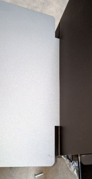
COMBUSTION CHAMBERS

Mendip Stoves are fitted internally with vermiculite heat deflection panels and baffles, these panels are designed to
ensure the maximum efficiency and are an integral part of the clean burn process of the stove. These baffles should not be
removed other than for cleaning the stove. Any defective panels should be replaced, small hairline cracks do not need
immediate replacement, however hairline cracks will develop during long term use and should be monitor regularly. When
refuelling your stove place wood fuel into the chamber, impact from logs can cause the heat deflection panel to crack.

Connection to chimney
Christon models are built with a top flue outlet as standard. Care should be taken to ensure an airtight fit if or when
refitting a collar. This collar allows connection to either a masonry chimney or a prefabricated factory made insulated
metal chimney.

  INSTALLING A CHRISTON INSET

                 Building in Dimensions            Height                Width                 Depth
               CHRISTON 550                       570 mm                570 mm                380 mm
               CHRISTON 750                       570 mm                770 mm                380 mm

             H

                                                                                                  D
                                                   W

                                     DO NOT OBSTRUCT THE AIR INTAKE
  At least 20mm clearance should be left between the outer casing of the rear of the stove and the wall

If you are installing an inset stove without utilising the closed combustion capabilities of the Christon wood
burners, you will need to remove the Direct Air Inlet at the rear of the stove to ensure that there is
sufficient air flow to accommodate the requirements of the appliance.

                                  DO NOT BACKFILL AROUND THIS STOVE
          It could block the air intake of your appliance, preventing it from operating as it should.

N.B. Inset models are supplied with a stainless steel adapter which allows direct connection to a stainless steel
chimney liner. ( See adapter shown on Christon 550 drawing)

                                                             8 of 40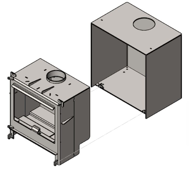
HOW TO OPERATE YOUR STOVE

Suitable fuels
Your stove is tested to burn wood. Wood briquettes can also be burnt but special account should be taken of fuel weight.
For a full list of suitable fuels, check with the official solid fuels approvals body, HETAS or Solid Fuel Association. Do not
overload stove as this can cause excessive heat and damage the stove (see table on page 5).

ALWAYS KEEP FUEL LOAD BELOW TERTIARY PORTS AT REAR OF STOVE. Only use fuels approved for use on heating stoves.
Do not burn liquid fuels, drift wood, finished wood, sawn wood, pallet wood, chipboard/plywood ,varnished wood or
plastic coated wood, wood treated with preservatives, or any house hold waste.

                           DO NOT EXCEED SPECIFIED FUEL WEIGHTS.
                  DO NOT BURN HOUSE COAL. DO NOT BURN HOUSEHOLD WASTE.
                           THIS APPLIANCE IS NOT AN INCINERATOR.

MENDIP STOVES RECOMMEND THE USE OF A FLUE THERMOSTAT TO CHECK YOUR STOVE IS NOT
OVERHEATING. PLACE FLUE THERMOSTAT DIRECTLY ABOVE COLLAR OF STOVE AND REFER TO
TEMPERATURE GAUGE ON PAGE 4.

    LIGHTING YOUR STOVE FOR THE FIRST TIME
Before lighting your stove for first time make sure you have read this manual fully and acquainted yourself with the
controls of this appliance. (see page 9)

The heat-resistant paint on your stove will cure and harden the first time you light your appliance.

The curing process produces a good deal of smoke and odour, it is therefore important that the first time you light your
stove the room should be well ventilated.

During the process it is important to open and close the stove door periodically (every 30mins) during the first couple of
firings therefore preventing the door seal cord around the door from sticking and coming away from the door. Once the
heat-resistant paint has hardened the smell will disappear.

Your stove is NOT designed to be used with the door open, the stove door must be kept closed except when lighting the
stove, adding firewood or removing ash in order to prevent flue gases from escaping.

Use of Fire lighters
Quality Firelighters should be used when lighting your stove. (Never use mentholated spirit, petrol or other flammable
liquids). Lighting your stove with firelighters will be more reliable and easier than using paper. Lighting your fire with
paper results in excess smoke, more ash and possible blackening of glass.

    OPERATING THE AIR CONTROL LEVER
The Universal Air Control Lever (UAC) determines how much air is admitted into your stove, as well as where it is
directed into the combustion chamber:

Sliding the control lever in and out respectively reduces and increases the total amount of air available to the stove.

      Minimum Air Input                                                                         Maximum Air Input
Moving the control lever from left to right determines where the external air is directed into the combustion chamber:
By moving the control lever to the left increases the primary air mix, moving the UAC to the right increases the
secondary air.

                      Maximum Primary Air Mix                     Exclusively Secondary Air
  Whatever position the control is set at, the lever can have either minimum combustion air or maximum combustion air.

                                                     9 of 40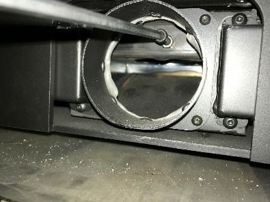
HOW TO LIGHT YOUR WOOD BURNING STOVE

Note: If the chimney is externally fitted or the stove has been installed
on a larger diameter clay chimney liner then on cold days it maybe
necessary to warm the flue using firelighters prior to lighting with wood.

1. Place a few smaller pieces of dry wood (kindling) in the stove on top of
the non toxic firelighters, place one or two small dry split logs (¼ split) on
top. Kindling stacked as in diagram allows combustion air flow freely and
will aid ignition.

2. Fully slide open (pull out ) the Universal air control (UAC) air slider below
the stove door. Slide out fully to the left position. The stove now has
a mix of primary air secondary air for start up.

3. Light the firelighters and push door to closed position, latch in 1st
position so the door is open 2 mm. (see picture) This provides additional
combustion air for start up and reduces condensation on the door glass.

                                 Maximum Primary Air Mix
4. Once the flames from the logs are fully established , this can take up to 10 min's . The door can now be
closed. Leave the UAC control in the left position (if the slider is in the left position the air controller is providing
a mix of primary and secondary air).If the stove flames begin to falter and generate smoke in chamber unlatch the
door again until the fire is established.

5. Once the fire bed is established slide UAC control
to the secondary position (right side) and push in
slider as desired, for the stove to burn cleanly plenty
of secondary air is needed, do not be tempted to shut
the fire down too early as this may cause smoke. At
nominal heat output, expect to refuel your stove
approximately once an hour. Check load weights for
your model on the table on page 5. And use the glove
when reloading, as well as when operating air
controls and door.

             The stove will get very hot during use and due care must therefore be exercised.
                   Please use the glove when operating air controls , door and ashpan.

WOOD FUEL
Good quality wood is the most important factor in your stove working efficiently and cleanly. Always use dry split
hardwood firewood (moisture content of 20% or less). The dryness of the firewood plays an important role since the use
of wet wood results in poor fuel economy and may cause a tarry sooty film on the internals of the stove.
                Newly cut wood contains 60–70% water, making it totally unsuitable for use as firewood.
        Newly cut wood should be stacked and air dried under cover for two years before being used as firewood.
   Do not burn liquid fuels, drift wood, finished, sawn wood, pallet wood, chipboard/plywood, varnished wood or
                     plastic coated wood, wood treated with preservatives, or house hold waste.

                                                             10 of 40
RE-FUELLING WHEN BURNING WOOD
To re-fuel your stove in the cleanest way only refuel your stove when flames have died down and you have glowing embers.
Before refuelling, open UAC fully and slide to the left position . Unlatch door to equalise pressure with the room. Open
door gently, add one piece of wood (4.8kW model) add two pieces of wood (8.7kW models) (please check weight table
page 5) and close the door. Once the flames from the logs are fully established slide UAC control to right position and
push air control as desired. The stove is only suitable for intermittent use only: do not run overnight or for long periods
unattended.
Experience will determine the settings that produce best results. Use a flue thermostat to check the stove is not overheating.
Flue thermostats should be placed directly above collar of the stove on a non insulated section of pipe. (efficient operating
temperature range is between 200c and 400c)
Log Length Time Intervals
Between
Maximum SE Dimensions Number of Logs Reloading Wood Reload
Length L x W x D cm Weight
CHRISTON 550 40cm 25 x 14 x 11 1 ~45min (0.72hr) 1.4kg
CHRISTON 750 60cm 25 x 14 x 14 2 ~50min (0.81hr) 1.84 kg
BURNING WOOD IN A SMOKE CONTROL AREA
You must purchase a smoke control version of the Mendip stove which is modified slightly to comply with regulations. Any
change to this modification will invalidate the stoves compliance for smoke control areas.
The Clean Air Act 1993 and Smoke Control Areas
Under the Clean Air Act local authorities may declare the whole or part of the district of the authority to be a smoke control
area. It is an offence to emit smoke from a chimney of a building, from a furnace or from any fixed boiler if located in a
designated smoke control area. It is also an offence to acquire an "unauthorised fuel" for use within a smoke control area
unless it is used in an "exempt" appliance ("exempted" from the controls which generally apply in the smoke control area).
In England appliances are exempted by publication on a list by the Secretary of State in accordance with changes made to
sections 20 and 21 of the Clean Air Act 1993 by section 15 of the Deregulation Act 2015. In Scotland appliances are exempted
by publication on a list by Scottish Ministers under section 50 of the Regulatory Reform (Scotland) Act 2014. Similarly, In
Northern Ireland appliances are exempted by publication on a list by the Department of Agriculture, Environment and Rural
Affairs under Section 16 of the Environmental Better regulation Act (Northern Ireland) 2016. In Wales appliances are
exempted by regulations made by Welsh Ministers.
Further information on the requirements of the Clean Air Act can be found here: https://www.gov.uk/smoke-control-area-rules
Your local authority is responsible for implementing the Clean Air Act 1993 including designation and supervision of smoke
control areas and you can contact them for details of Clean Air Act requirements.
The Christon 550 & 750 SE stoves have been recommended as suitable for use in smoke control areas when burning wood
logs. The appliances have been fitted with a modification to fix the air controls at 0% open for 550 & 50% open for the 750
model in its minimum position.
Only specific SE cleanheat models are suitable for smoke control areas (page 5), alterations should not be attempted.
Mendip smoke control stoves should not be burnt with the door left open.
The refuelling procedure : - allow the newly charged fuel to burn with the secondary air control set at maximum for up 3 to
4 minutes. After this period, with flames from the logs fully established, close the secondary air supply to the low output
setting. When operating at high output (secondary air set fully open) the new refuel charge does not require any boost air
to establish combustion.
11 of 40BURNING WOOD IN A SMOKE CONTROL AREA - continued
Refuelling on to a low fire bed
If there is insufficient burning material in the firebed to light a new fuel charge, excessive smoke emission can occur. Refuelling
must be carried out onto a sufficient quantity of glowing embers and ash that the new fuel charge will ignite in a reasonable
period. If there are too few embers in the fire bed, add suitable kindling to prevent excessive smoke
Operation with door left open
Operation with the door open can cause excess smoke. The appliance must not be operated with the appliance door left
open except as directed in the instructions.
Dampers left open
Operation with the air controls or appliance dampers open can cause excess smoke. The appliance must not be operated
with air controls, appliance dampers or door left open except as directed in the instructions.
Fuel Overloading
The maximum amount of fuel specified in this manual should not be exceeded, overloading can cause excess smoke
SE Cleanheat - SMOKE EXEMPTION MODIFICATION
Smoke exempt models are factory fitted with a air stop
on the air control slider: The adjust control to smoke
control settings place Allen key on bolt in the air
intake ( at the rear of the stove ensuring that the air
control is limited to
● No limit is needed for Christon 550
● Reduce travel to 2.5 cm/50% for Christon 750
SOLID FUEL - COAL - SMOKELESS COAL
SMOKELESS COAL, HOUSE COAL AND PETROLEUM COKE ARE NOT
SUITABLE FOR USE ON THIS STOVE; ITS USE WILL INVALIDATE THE
GUARANTEE.
SOLID SMOKELESS FUELS - Christon 550/750 models are NOT suitable for use with smokeless fuels and have not been
tested to the relevant European standard. Only use wood for these stoves.
12 of 40INCOMPLETE COMBUSTION
If the air controls on your stove are closed too much incomplete combustion may lead to a build-up of hard, shiny soot on
the inside of your stove and glass. To prevent sooting of the chamber and glass introduce:-
1) more secondary air,
2) check that your fuel is suitable and dry.
3) that you have sufficient draw in your chimney.
It is important to check the draft conditions before lighting your stove. This may be done, for instance, by crumpling a piece
of newspaper, placing it in the combustion chamber and lighting it. The draft conditions are good if the smoke is drawn away
through the chimney.
OVERNIGHT BURNING
Mendip Christon stoves are designed to burn wood . Wood burns more efficiently and cleanly if it is burnt hotter. Mendip
stoves do not recommend that their stoves are burnt overnight for this reason. As a night time regime we recommend that
the fire is loaded when hot and burnt for five minutes with the secondary air control fully open until the new wood has taken
and is burning, then close the secondary air valve to its operational position. On returning to the stove in the morning the
fire will have burn out, reload with some paper or firelighter and some kindling and open both air sliders fully to relight
quickly. Beware as the ash bed will have hot embers.
PERMANENT AIR VENT
The stove requires a permanent air vent to the room . This is to provide adequate air supply in order for the stove to operate
safely and efficiently. In accordance with current Building Regulations the installer may have fitted a permanent air supply
vent into the room in which the stove is installed to provide combustion air. This air vent should not under any circumstances
be shut off or sealed.
13 of 40WARNING NOTE
Properly installed, operated and maintained this stove will not emit fumes into the dwelling. Occasional fumes from
de-ashing and re-fuelling may occur. However, persistent fume emission is potentially dangerous and must not be
tolerated. If fume emission does persist, then the following immediate action should be taken:-
(a) Open doors and windows to ventilate the room and then leave the premises.
(b) Let the fire go out.
(c) Check for flue or chimney blockage and clean if required
(d) Do not attempt to relight the fire until the cause of the fume emission has been identified and corrected. If necessary
seek expert advice.
The most common cause of fume emission is flue way or chimney blockage. For your own safety these must be kept clean
at all times.
CO Alarm
Your installer should have fitted a CO alarm in the same room as the appliance. If the alarm sounds unexpectedly, follow
the instructions given under “Warning Note” above.
Aerosols
Aerosols are flammable and therefore dangerous to use around a lit stove. Do not use aerosols sprays near your lit stove.
The use of any aerosol is dangerous and care must be taken handling aerosols.
TROUBLE SHOOTING
1. Fire Will Not Burn - check 3) Soot forms on the window
a) the air inlet is not obstructed in any way, a) The firewood may be too wet
b) that chimney and flue ways are clear, b) the intake of secondary air may be insufficient
c) that a suitable fuel is being used, c) fire not hot enough
d) that there is an adequate air supply into the room,
e) that an extractor fan is not fitted in the same room as 4) The stove fails to heat fully
the fire. a) The firewood may be too wet
b) the intake of secondary air may be insufficient
2. Fire Blazing Out Of Control - check
a) the doors are tightly closed, 5) Smoke or odour
b) the air controls are turned down to the minimum a) weak chimney draft
setting, b) check for blockages in the flue pipe/chimney
c) the flue damper is closed ( if fitted), c) check the height of the chimney relative to the
d) a suitable fuel is being used, surroundings
e) the door seals are in good condition.
F) the chimney draft may be too strong 6) Soot in the chimney
G) check ash pan seal and a) The firewood may be too wet
H) check for ash below ash pan causing pan to seat b) intake of secondary air may be insufficient
incorrectly and clean out.
14 of 40MAINTENANCE
Mendip stoves recommends that your model needs to have the ash removed from the Christon stove at regular intervals
(every 2-3 days if used daily). Overflowing ash will impede the function of the stove and can cause possible damage to the
stove linings. To remove ash pan use a ash shovel, always wear a heat resistant glove. Make sure the stove is completely
cold before cleaning out ash (embers can remain hot for over 24 hours).
Ash must be stored in a non-combustible container and must not be mixed with other combustible waste.
Annual service
The inside of the stove should be serviced /cleaned once a year. To clean the inside, remove all ash, soot and tar residue
from the combustion chamber. Remove insulated chamber panels and baffle, dirt and soot will collect behind it and this
must be cleaned out. Check the quality of all insulated panels and replace any which are damaged or cracked, replace stove
door rope cord in the door. Check glass is correctly positioned. The stove, the flue pipe connection and the chimney should
be checked regularly by a qualified engineer. The chimney should also be checked for blockages before relighting the stove
if it has not been used for an extended period of time. The paint/ lacquer can wear thin in exposed places due to overheating.
This, and other lacquer damage, may be repaired using Senotherm paint/lacquer spray available from your Mendip dealer.
To clean the outside of the stove use a dry cloth.
Prolonged non use (summer)
If the stove is to be left unused for a prolonged period of time (e.g. over the summer) then it should be given a thorough
clean to remove ash and unburned fuel residues. To enable a good flow of air through the appliance to reduce condensation
and subsequent damage, leave the air controls fully open.
It is important that the flue connection, any appliance baffles or throat plates and the chimney are swept prior to lighting up
after a prolonged shutdown period.
Spare parts & unauthorised alterations
Only the manufacturer's own components, or replacement parts recommended and approved by Mendip stoves, shall be
used for appliance servicing and repair. Any unauthorised alterations will invalidate the stove warranty and compliance with
EN13240.
SWEEPING YOUR CHIMNEY & CHIMNEY FIRES
Ensure that your appliance, flue ways and chimney are swept regularly. This can be incorporated in the service regime of
your appliance. Regular sweeping is essential and means at least once a year for smokeless fuels and a minimum of twice
a year for wood . If a throat/baffle plate is incorporated, it is essential that the throat/ baffle plate is removed and cleaned
above, all ash and debris should be removed. Ensure adequate access to cleaning doors where it is not possible to sweep
the chimney through the appliance.
Where a chimney has served an open fire installation previously it is possible that the higher flue gas temperature from a
closed appliance may loosen deposits that were previously firmly adhered, with the consequent risk of flue blockage. It
is therefore recommended that the chimney be swept a second time within a month of regular use after installation of the
stove.
Chimney Fires
If the chimney is thoroughly and regularly swept, chimney fires should not occur. However, if a chimney fire does occur turn
the air control setting to the minimum, and tightly close the doors of the stove. This should cause the chimney fire to go
out in which case the control should be kept at the minimum setting until the fire in the stove has gone out. The chimney
and flue ways should then be cleaned. If the chimney fire does not go out when the above action is taken then the fire
brigade should be called immediately.
After a chimney fire the chimney should be carefully examined for any damage. Expert advice should be sought if
necessary
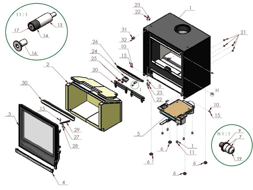
15 of 40STOVE PARTS, COMBUSTION CHAMBER, ASSEMBLY
PIÈCES DÉTACHÉES, VUE ÉCLATÉES
This section shows the parts contained in your stove, each stove has over 80 spare-parts and, each part is detailed. When
new parts are required the section will allow spares to be recognised and ordered. As a further source of reference please
visit www.eurostove.co.uk for latest spare-part information.
Cette section montre les pièces contenues dans votre poêle, chaque poêle a plus de 80 pièces de rechange et, chaque élément
est détaillée. Lorsque de nouvelles pièces doivent la section permettra aux pièces de rechange d'être reconnus et commandé.
Comme autre source de refernece nous avons aussi un liste de prix avec vues eclates avex les information sur pièces de
rechange.
LOOSE PARTS / PIÈCES DÉTACHÉES
Always use the operating tools provided when
handling parts likely to be hot when the stove is in
use. Your stove has the following parts in the stove.
1. Foot Adjustment Tool
2. Stove Glove
3. Instruction Manual & Warranty Card
4. Vermiculite Fire Bricks ( these are integral to
the stoves performance - Do NOT throw away)
5. Moisture absorbency bag
Toujours utiliser les outils prévus pour manipuler 1. Outil de réglage du pied
les pièces susceptibles d'être chaudes lorsque le 2. Gant
poêle est en cours d'utilisation. Votre poêle 3. Guide d’utilisation et bon de garantie
comprend les éléments suivants dans le poêle. 4. Briques réfractaires, elles font partie intégrante du poêle, ne
pas jeter.
5. Sac absorbant d’humidité
16 of 40CHRISTON 550 / 750 COMBUSTION CHAMBER SPARE PART CODES
CHAMBRE DE COMBUSTION INTÉRIEUR DU CHRISTON 550 / 750
5L
8 5R
7 4 EST_2
5 EST_2
6 EST_2
7 EST_2
8 EST_2
4L
5 4R
3 3
2L 2R
6
1 1
1
1
17 of 40CHRISTON 550 / 750 BRICK SET REFERENCE KEY AND PRODUCT CODES
RÉFÉRENCES POUR LA BRIQUES ET CODES DE PRODUITS DU CHRISTON 550 / 750
Figure # Part Description Christon 550 - Part Code Christon 750 - Part Code
1 Base Brick Pair M10550-02-22-99-00 M10750-02-22-99-00
2 Rear Brick Pair M10550-02-23-99-00 M10750-02-23-99-00
3 Side Brick Pair M10550-02-24-99-00 M10750-02-24-99-00
4 Baffle Brick Pair M10550-02-26-99-00 M10750-02-26-99-00
5 Upper Baffle Brick Pair M10550-02-58-99-00 M10750-02-58-99-00
CHRISTON 550 / 750 COMBUSTION CHAMBER
CHAMBRE DE COMBUSTION INTÉRIEUR DU CHRISTON 550 / 750
Secondary air
/air wash
Baffle support Aire secondaire
bar
Barre de support
de déflecteur Tertiary Air jets
Alimentation de
L’air tertiaire
Vermiculite
brick set
Jeu de plaques
vermiculites
Rear firebrick
support bracket Log retainer
Patte de support Arrêt de bûches
pour déflecteur
Primary air box
Aire primaire
18 of 40HOW TO REMOVE A VERMICULITE BRICK SET
MONTAGE ET DÉMONTAGE DE L’INTÉRIEUR
Remove log retainer by lifting out.
1 Enlever l’arrêt de bûches. 2
Remove the baffle support bar.
Retirez la barre de support du déflecteur.
Lift the right hand baffle brick and position
it to the right allowing more room to remove
the left hand baffle.
Soulevez la brique de déflecteur droite et
placez-la vers la droite, ce qui laisse plus
d'espace pour retirer le déflecteur gauche
3 Tilt the left hand baffle brick forwards and 4
towards the centre to remove. Repeat this
for the right hand baffle.
Inclinez la brique de déflecteur gauche vers
l'avant et vers le centre pour la retirer.
Répétez cette opération pour le déflecteur
de droite.
Unscrew and remove the rear brick support
bracket.
Dévisser et retirer le support de brique
arrière.
5 Remove the upper baffle support bracket.
6
Retirez le support du déflecteur supérieur.
Tilt an upper baffle brick forward and to the
centre in order to remove.
Inclinez une brique de déflecteur supérieure
vers l'avant et vers le centre pour la retirer.
Your flue system can now be accessed
through the stove, but for added protection
when sweeping, it is advised that all the
bricks be removed.
7 Vous pouvez maintenant accéder à votre
système d'évacuation par le poêle, mais pour
8
plus de protection lors du balayage, il est
conseillé de retirer toutes les briques.
As the baffle bricks are no longer present,
the side bricks can be removed from the
combustion chamber.
Les briques de déflecteur n'étant plus
présentes, les briques latérales peuvent être
retirées de la chambre de combustion.
The absence of the side bricks means that
9 the base bricks can be lifted out.
Sans les briques latérales, il est possible de
10
soulever les briques de base.
The rear bricks are now unsupported and
can be freely removed.
Les briques arrière ne sont plus supportées
et peuvent être enlevées librement.
To reinstall the brick set follow these instructions in reverse
Pour réinstaller ce jeu de briques, appliquez ces instructions à l'envers.
19 of 40CHRISTON 550 /750 COMBUSTION CHAMBER CAN BE REMOVED FROM OUTER FRAME
CHAMBRE DE COMBUSTION INTÉRIEUR DU CHRISTON 550 / 750
Christon 550 Freestanding / Inset
Christon 750 Freestanding / Inset
20 of 40CHRISTON 550 SPARE PART DIAGRAM
CHAMBRE DE COMBUSTION INTÉRIEUR DU CHRISTON 550 / 750
Christon 550 Freestanding
Christon 750 Freestanding Christon 750 Inset Christon 550 Inset
To purchase or get more information on spare parts for the Christon Models, please visit:
www.mendipstoves.co.uk/mp-spares-christon-category
21 of 40CHRISTON 550 /750 DOOR & HANDLE CONSTRUCTION
CHAMBRE DE COMBUSTION INTÉRIEUR DU CHRISTON 550 / 750
Number Description Christon 550 Product Code Christon 750 Product Code
Complete Door M10550-06-00-00-00 M10750-06-00-00-00
1 Door Handle M10750-06-05-99-00 M10750-06-05-99-00
2 Glass M10550-01-27-99-00 M10750-01-27-99-00
3 Door Rope Seal M10550-06-02-00-00 M10750-06-02-00-00
4 Glass Rope Seal M10550-01-02-01-00 M10750-01-02-01-00
5 Door Frame M10550-06-01-00-00 M10750-06-01-00-00
6 Retention Nut
7 Glass Trim M10550-01-03-00-00 M10750-01-03-00-00
22 of 40LOGSTORE INSTALLATION
1. When attaching a logstore to the Christon 550 or 750,
the first thing to do is to prepare the base by ensuring all
1 the bolts, as well as the front bar, have been separated
from the stand.
2. Then place wooden batons on top of the base; this
enable the Christon stove to be placed onto the logstore
without trapping your fingers. Please observe safe lifting
practices and do not attempt to lift this stove alone.
These batons should be 50mm (2 inches) thick to provide
enough space to access and remove the levelling feet.
The tool provided for adjusting the height of the feet can
also be used to remove the feet.
2 3. Once the feet have been removed, roughly position
the stove inline with the base. Then carefully lift one side
of the stove and remove the wooden batons, allowing
the stove to come to rest upon the logstore.
4. It is unlikely that the stove body and logstore base are
perfectly aligned. The other end of the foot adjustment
tool can then be used to lever the two components on a
horizontal plane with the help of the purpose-built
alignment groves either side of the closed combustion
inlet.
5. Now the two are inline, the logstore can be secured
using the bolts provided. The front two bolts need to be
3 attached with the front cover strip (as shown in the
photo). These bolts should be fastened using an Alan key
to ensure that the stove is well secured to the base.
You have now successfully attached the logstore.
5
4
6
23 of 40SIDE TABLE INSTALLATION
Firstly, to assemble you side table:
Place the top plate onto the body of the side
table and use M5 nuts and a spanner/socket
wrench to secure the top plate in the correct
1 position.
3
2 4
Once you have your side table, simply slide the top plate protrusion between
the stove body and the log base (�). If this has been positioned correctly
the threaded holes of the top plate will be accessible through the logstore
base of the Christon.
Then secure the Side Table to the Logstore using M5 countersunk screws -
To avoid damaging the thread, tighten the screws with your fingers to start
with and then fully secure them with an Alan key/socket wrench as shown
in the photo.
It’s that simple!
5 6 7
24 of 40FRANÇAISE
Guide d’utilisation et Mode d'Emploi
CHRSTON 550 CHRISTON 550 INSERT
CHRISTON 750 CHRISTON 750 INSERT
Ce manuel se réfère aux poêles énumérés ci-dessus. Ils ont été testés conformément à la norme EN 13240 et 13229.
Nous vous remercions d'avoir choisi un nouveau poêle de Mendip Stoves et nous sommes certains que vous en serez
enchantés.
Lisez ces instructions, elles relatent les principes de base pour assurer l'installation satisfaisante de votre poêle, même si
pour répondre à des conditions particulières locales, de légères modifications peuvent intervenir
Poêle a bois Hauteur mm Largueur mm Profondeur mm Poids kg
Christon 550 550 550 360 81
Christon 550 Insert 550 550 360 91
Christon 750 550 750 360 110
Christon 750 Insert 550 750 360 120
25 of 40CONSIGNES GENERALES DE SANTE ET DE SECURITE
--------------------------------------------------------------------------------------------------------------------------------------------------------------------
INFORMATIONS DESTINEES A L'UTILISATEUR, A L'INSTALLATEUR ET A L'INGENIEUR DE SERVICE
--------------------------------------------------------------------------------------------------------------------------------------------------------------------
Lors de l'installation du poêle, vous devez vous assurer de la conformité aux lois sur la santé et la sécurité au travail.
Manutention
Des installations et équipements adéquats doivent être disponibles pour les chargements, déchargements et manœuvres
sur le site.
TRAVAIL PREPARATOIRE ET CONTROLES DE SECURITE
Pièces en métal
Prenez toutes les précautions nécessaires lors de l'installation ou de l'entretien de ce poêle pour éviter les blessures.
AVERTISSEMENT IMPORTANT
Ce poêle ne doit pas être installé dans une cheminée servant à d'autres appareils de chauffage. La pièce où est placé le poêle
ne doit pas être équipée d'un dispositif d'extraction (VMC par exemple) car ceci pourrait provoquer des fumées en provenance
du poêle.
Poêle peinture aérosols
Le peintures aérosols sont inflammables et donc dangereux lors de l’utilisation autour d'un poêle en fonctionnement. Il faut
permettre au peinture de sécher et aéré la pièce avant l’allumage de l’appareil
Ciment réfractaire
Certains types de ciments réfractaires sont caustiques et ne doivent pas entrer en contact avec la peau. Après tout contact
avec les yeux, laver immédiatement et abondamment à l'eau.
Amiante
Ce poêle ne contient pas d'amiante. Si l'installation exige une manipulation d'amiante, contactez un spécialiste et utilisez
l'équipement de protection adapté.
Ces instructions concernent les principes fondamentaux de bonne installation des poêles multi
combustibles Mendip Stove.
Toutefois, l'installation doit répondre à la législation en vigueur et aux autres spécifications ou
règlementations affectant l'installation du poêle.
26 of 40CHEMINÉE ET RACCORDEMENT AU POÊLE À BOIS
La sortie de la cheminée doit être au-dessus du toit de l'habitation en conformité avec les dispositions du Règlement locale
en France. Si l'installation est dans une cheminée existante, alors le conduit existant doit être solide et ne pas avoir de fissure
ou autres défaut qui pourraient faciliter la diffusion des fumées dans l’habitat. Les habitations très anciennes peuvent
présenter des défauts de conduit ou des sections transversales trop importantes, c’est à-dire, plus de 160 mm x 160 mm.
La société Mendip Stoves conseille l'utilisation d'un système de conduit de fumée de combustibles solides pour l'installation
dans des cheminées existantes. Tous les systèmes de cheminée doivent être utilisés conformément au Règlement de
construction approuvé. Si une cheminée existante est utilisée, la cheminée doit être exempte de toute obstruction et doit
être nettoyée immédiatement avant l'installation du poêle. La cheminée doit être testée pour vérifier la dépression nécessaire
au bon fonctionnement du poêle. Si le poêle est installé à la place d'un feu ouvert, la cheminée doit être ramonée un mois
après l'installation afin d’éliminer toute suie existante lié à une combustion différente poêle -cheminée.
S’il n'y a pas de cheminée existante, soit une cheminée de blocs préfabriqués en conformité avec des règles de construction
ou un jumeau murée isolée conduit inox BS 1856-1 alors ces cheminées doivent être installées conformément aux instructions
du fabricant et des règles de construction. Un tubage de cheminée métallique à paroi simple est adapté pour le raccordement
du poêle à la cheminée mais ne convient pas pour l'utilisation de la cheminée complète. La cheminée et le conduit de fumée
de liaison doivent avoir un diamètre minimal de 150 mm et sa dimension ne doit pas être inférieure à la taille de la buse de
sortie du poêle à bois. Tout coude dans la cheminée ou le tuyau de raccordement du conduit de fumée ne doit pas dépasser
45°.
Les coudes de 90° ne doivent pas être utilisés autrement que dans les 150 mm de sortie de la cheminée de l'arrière du poêle.
Cheminée & Tirage
Pour faire fonctionner le poele de façon satisfaisante la hauteur de la cheminée doit être suffisante pour assurer
un tirage adéquat pour effacer les produits de combustion et de prévenir les problèmes de fumée dans la pièce.
Les résultats des tests pour
Combustion taux – Température de fumée
des débits et des bois/charbon @ Aspirartion Pa
températures d'émission bois/charbon
Christon 550 5.7g/s 220°C 12 pa.
Christon 750 7.6g/s 274°C 12 pa.
Une cheminée de 4 m 50, mesurée verticalement à partir de la sortie de la buse du poêle à la partie supérieure de la cheminée
doit être satisfaisante. Sinon la procédure de calcul donnée dans la norme BS 5854: 1980 peut être utilisée comme base
pour décider si la conception de cheminée fournira suffisamment de tirage.
Si l'on constate qu'il y a un tirage excessif dans la cheminée alors on peut effectuer un réglage de fumée manuel ou installer
un stabilisateur de tirage. Le réglage de la cheminée ajustable ne doit pas fermer la fumée entièrement mais devrait dans
sa position fermée quitter une zone continue minimale d'ouverture libre d'au moins 20% de la superficie totale de la section
transversale du conduit de cheminée ou ventouse. Une trappe de ramonage doit être prévue et accessible pour faciliter le
ramonage de la cheminée et du conduit de raccordement. Votre appareil doit être entretenu régulièrement, le déflecteur
doit être nettoyé régulièrement (tous les mois). Le conduit de fumée peut être nettoyé avec une brosse souple. Utilisez
uniquement un chiffon sec sur les surfaces externes. Au fil du temps le verre peut devenir sale, nettoyez avec un chiffon
humide et polir avec un chiffon humide. Si le poêle n'a pas été utilisé pendant un certain temps le conduit de fumée doit
être vérifié pour éviter tout blocage avant utilisation. Ne pas modifiez l’appareil ; utilisez uniquement des pièces de rechange
autorisées par le fabricant.
27 of 40INDICES DE PERFORMANCE ET RÉSULTAT DES TESTS
Christon Poêles à bois et inserts sont conforme au standard EN 13240 et 13229 et Eco Design 2022
Puissance Rendement CO@13% O₂ Particle Indice performance
bois mg/NM³
Christon 550 4.8 kW 77.8% 0.09 30 0.5
Christon 750 8.7 kW 78.4% 0.09 32 0.6
Max longueur de bûche, Quantité et la fréquence de recharge.
Buches specification
Longeur Dimension Qte Temps de Poids de recharge
LxHxP Recharge Hr
Christon 550 40cm 25 x 14 x 11 1 0.79hr 1.0kg
Christon 750 60cm 25 x 14 x 11 2 0.81hr 1.6kg
ECO DESIGN READY - ADAPTE AU BESOIN DE MARCHÉ FRANCOIS
Les modelés de Christon sont livre avec un control sur la fermeture des aires secondaire pour arrive au besoin des normes
Eco Design et arrive au niveau de performance pour l’éligibilité au crédit impôt entre autre standard en France.
Par contre nous avons adapté les poêles telle qu’il est possible de diminuer cette control sur les aires. Pour permettre les
poêles de fermer les aires plus et augmenter le durée de fonctionnement entre les rechargements de bois. Vous pouvez
augmenter le mouvement du UAC (Control des aires).
Viser le vis allen trouvée dans l’entre d’aire directe derrière le poêle dans
le sens antihoraire pour augmenter votre control des aires. Viser dans le
sens de l’horaire jusque a maximum 50% pour réduire votre control des
aires.
- Besoin sur Christon 550 – faible influence
- Besoin sur Christon 750 jusqu’ a 2.5 cm/50% influence notable
Astuce de l’aire secondaire.
Viser le vis allen dans entre d’aire directe derrière le poêle dans le sens
antihoraire pour augmenter votre control des aires. Viser dans le sens de
l’horaire jusque a maximum 50% pour réduire votre control des aires.
DISTANCE
Distance AUX MATÉRIAUX
aux matériaux inflammables INFLAMMABLES
Les matériaux combustibles ne doivent pas être situés à proximité de la diffusion de la chaleur à travers les parois des poêles
ou cheminées; ils pourraient s’enflammer. Par conséquent lors de l'installation du poêle, il faut respecter les distances de
sécurité données dans le Règlement de construction local mais aussi dans les instructions du poêle établies à la suite de
tests. Les distances minimum des matériaux inflammables sont indiquées sur la plaque EN 13240 au dos du poêle à bois.
Convenable plaque plancher
Distance de sécurité arrière Distance de sécurité latérale
(12mm)
Christon 550 200mm 200mm OUI
Christon 750 100mm 100mm OUI
28 of 40DIMENSIONS DES POÊLES ET DE TAILLES DE RACCORDEMENT
D E
A
H
B
C
Dimensions Poele Distance au
Hauteur Largeur Profond Buse Dos/Axe Sol/axe Raccordement
mm mm eur mm raccordement raccordement raccordmenet aire aire mm
mm fumee mm mm
A B C D E H
Christon 550 550 550 360 125 105 50-60 80
Christon 750 550 750 360 150 105 50-60 80
H) “La variance de hauteur d'entrée sur l'entrée d'air direct dépend du réglage des pieds »
29 of 40FOYER
Le foyer doit être capable de supporter le poids du poêle et de sa cheminée. Modèles Christon 550 / 800 sont testés et
adaptés pour être installés sur une plaque non- combustible de 12 mm comme une plaque de sol verre de 12 mm ou une
plaque d'ardoise de 20mm. L’Installation de tous les foyers doit se conformer à la taille et la construction de sorte qu'il est
en conformité avec les dispositions de Règlement locale.
Les distances de sécurité aux matériaux inflammables autour, à l’arrière du foyer doivent se conformer aux normes fixées
dans le Règlement de construction locales et aussi dans ce guide d’utilisation. Si le poêle doit être installé sur un plancher
en bois, il doit être recouvert d'un matériau non-combustible et conformément aux règles de construction locales à une
distance de 30 cm devant le poêle et 15 cm du côté latérale du poêles.
AIR DIRECT ET POELE ETANCHE
Il est nécessaire de prévoir avec le poêle des entrées d'air suffisantes pour un fonctionnement efficace, pour assurer la
sécurité des habitants et parer à toute éventualité. Cela est particulièrement nécessaire si la pièce disposes un double vitrage,
si un stabilisateur de tirage de fumée est monté sur l'appareil, ou encore si des systèmes d'échangeur de chaleur de l'air à
pression négative sont utilisés. La fourniture de l'alimentation en air du poêle doit être conforme aux règles de construction
locales actuelles. Une fenêtre ouverture ne convient pas à cet effet. Les entrées d'air doivent être positionnées de telle sorte
qu'elles ne peuvent pas être bloquées. Une entrée d'air peut être une ouverture (cette sortie doit être ouverte et assurer
sa fonctionnalité lorsque le poêle est allumé).
Il n'y a pas de règles européennes concernant la distance minimale des murs non-inflammables, Mendip Poêles recommande
de laisser une distance d'au moins 100 mm à l’arrière et sur les côtés du poêle. Les Modèles Christon 550 / 800 prennent
l'air de combustion à partir d'une seule ouverture de 80mm sous le poêle, une fois la porte fermée l’amenée d'air fournit
tout l'air de combustion de l'appareil. Celui-ci peut être relié à l'extérieur par un tuyau de 80 mm de sorte que le dispositif
ne prenne pas d'air de la pièce. Cependant, Mendip Poêles recommande toujours l'utilisation d'une arrivée d’air dans la
pièce suffisante pour permettre la reconstitution rapide de l'air ambiant pour les habitants en cas de problème.
CHAMBRES DE COMBUSTION
La chambre de combustion Mendip, les panneaux de vermiculite sont conçus pour assurer le maximum d'efficacité et sont
une partie intégrante du processus de combustion propre au poêle. La vermiculite ne doit pas être enlevée autrement que
pour nettoyer le poêle. Tous les panneaux brisés défectueux doivent être remplacés, mais la présence de petites fissures ne
nécessite pas de remplacement immédiat. Pour éviter les dommages accidentels potentiels de briques, placez le bois dans
le foyer tout en portant un gant lors du ravitaillement, éviter de jetez les bûches; l’impact à partir des bûches peut causer
des fissures prématurées au niveau des panneaux de vermiculite.
Raccordement pour cheminée
Les poeles Mendip Christon sont construits avec une sortie par le haut en standard. Des précautions doivent être prises pour
assurer un ajustement étanche à l'air lors du montage du collier et de la plaque. Une plaque de couvercle décorative est
inclue dans chaque poêle pour couvrir le trou dans la plaque supérieure de convection. Ce collier permet la connexion soit
à une cheminée de maçonnerie, à une pièce d’usine préfabriquée isolée, ou à une cheminée en métal. Il faut s’assurer que
les pièces détachées (en briques et grilles) soient montés conformément aux instructions données dans le guide d'utilisation.
À l'issue de l'installation, prévoir une période de temps convenable pour que tous les mastics d'incendie sèchent, un petit
feu peut être allumé pour vérifier que la fumée et les vapeurs sont prises du poêle vers la cheminée et émises en toute
sécurité dans l'atmosphère. Ne pas faire fonctionner l’appareil à pleine puissance pendant au moins 24 heures.
MIS EN SERVICE
Au terme de l'installation, les instructions d'utilisation sont laissées au client. Assurez-vous de conseiller le client sur
l'utilisation correcte de l'appareil avec les combustibles susceptibles d'être utilisés dans le poêle et notifier leurs
l’utilisation de combustibles recommandés pour le poêle. Transmettez les recommandations nécessaires à l'utilisateur en
cas d’émanations de fumées par le poêle. Le client doit être averti de l’utilisation d’un pare-feu à la norme BS 8423: 2002,
en présence des enfants, ou de personnes âgés ou infirmes.
30 of 40You can also read