Conformable Actuation and Sensing with Robotic Fabric
←
→
Page content transcription
If your browser does not render page correctly, please read the page content below
2013 IEEE/RSJ International Conference on
Intelligent Robots and Systems (IROS)
September 14-18, 2014. Chicago, IL, USA,
Conformable Actuation and Sensing with Robotic Fabric
Michelle Yuen1 , Arun Cherian1 , Jennifer C. Case1 , Justin Seipel1 , Rebecca K. Kramer1∗
Abstract— Future generations of wearable robots will include
systems constructed from conformable materials that do not
constrain the natural motions of the wearer. Fabrics represent
a class of highly conformable materials that have the potential
for embedded function and are highly integrated into our daily
lives. In this work, we present a robotic fabric with embedded
actuation and sensing. Attaching the same robotic fabric to
a soft body in different ways leads to unique motions and
sensor modalities with many different applications for robotics.
In one mode, the robotic fabric acts around the circumference
of the body, and compression of the body is achieved. Attaching
the robotic fabric in another way, along one surface of a
body for example, bending is achieved. We use thread-like
actuators and sensors to functionalize fabric via a standard
textile manufacturing process (sewing). The actuated fabric
presented herein yields a contractile force of 9.6N and changes
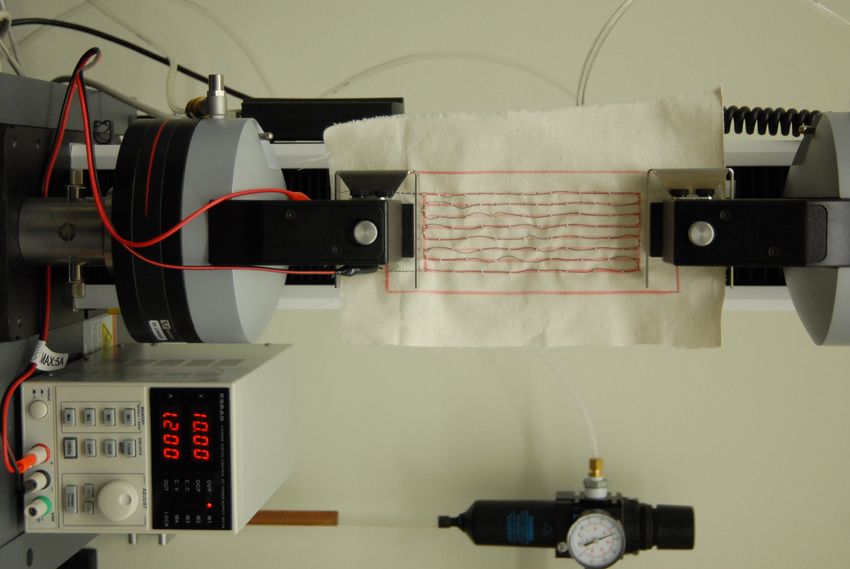
in length by approximately 60% when unconstrained. The Fig. 1: Application of the same robotic fabric towards different
integrated strain sensor is evaluated and found to have an modes of motion: (a) flexing of a hinge joint and (b) compressing
RMS error of 14.6%, and qualitatively differentiates between a soft body.
the compressive and bending motions demonstrated.
I. I NTRODUCTION In this work, we present a functionalized fabric embedded
Robots have the incredible power to amplify human pro- with actuators and sensors. Because the actuators and sensors
ductivity and enhance our capabilities, and by doing so shape integrated in the fabric base are also thread-like in terms of
the world we live in. The use of the word robotic implies shape, size and flexibility, the functionalized fabric retains
a rigid, bulky, and complex device; however, the emerging the conformable nature of its fabric base. To illustrate the
fields of soft robotics and wearable robotics counter this versatility of robotic fabrics, we present two modes of
implication by exploring the use of conformable materials as actuation using the same robotic fabric on a soft foam block:
actuators and sensors. In particular, we believe that fabrics (1) bending, employing linear contraction along the length
will play a large role in the future of soft and wearable robots, of the foam, and (2) compression, employing radial pressure
and could be employed in applications such as active cloth- by wrapping the fabric around the foam midsection. For both
ing, active joint braces, or wearable interfaces. By treating modes of actuation, we test and report on the behavior of the
clothing as a field of engineering, it can be transformed from robotic fabric.
passive apparel to active equipment, assisting its wearer by We use shape-memory alloy (SMA) wire as the actuation
enhancing strength, improving stamina, or preventing injury. mechanism. The SMA is programmed to remember a helical
As fabrics are already heavily integrated into our daily lives, coil when heated, which was previously shown to increase
robotic fabrics will be natural for people to wear and interact the actuator change in length from between 4-10% to as
with, both minimizing discomfort and maximizing efficiency. much as 50% [1]. The sensors used in this study are custom-
Robotic fabrics can also be customizable across differ- made by filling soft silicone tubing with liquid-metal. When
ent hosts and utilized differently depending on the host. the tubing is strained or compressed, the cross-sectional
For example, a fabric sleeve with intermittent compression area of the encased liquid-metal is deformed, resulting in a
actuators may be worn by a human to create peristaltic- change in electrical resistance. Both the actuator and sensor
like flow of fluids within the muscle to aid in post-exertion components were chosen to mimic the compliance, strength,
recovery, and this same fabric could be placed on a cylin- and usability of threads in fabric. As such, they can be
drical deformable body to create peristaltic-like locomotion. integrated with fabrics using standard textile manufacturing
Similarly, a linearly actuating fabric might be applied to approaches, such as sewing.
produce contraction, bending or compression of different Robotic fabrics could be incorporated into wearable inter-
hosts. faces and electronics such as communication devices, wire
harnesses and conformable antennas, as well as assistive
∗ Author to whom correspondence should be addressed fabrics for motion aid, prolonged endurance, and health-
rebeccakramer@purdue.edu
1 Schoolof Mechanical Engineering, Purdue University, West Lafayette, monitoring. Furthermore, robotic fabrics have applications
IN 47907, USA in on-the-fly robot design in cases where function may need
978-1-4799-6933-3/14/$31.00 ©2014 IEEE 580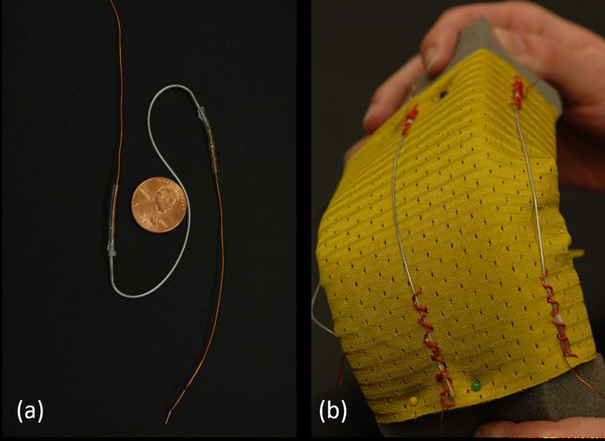
to be adjusted on-demand, such as with exploratory robots
or first-responder robots.
                    II. P REVIOUS W ORK
   Smart fabrics [2], [3], [4], [5] are generally fabrics that
incorporate some electronic component(s) for medical mon-
itoring or wearable computing [6], [7]. Components and
connections are meant to be intrinsic to the fabric and
therefore less intrusive in daily tasks than other potential
forms of wearable computing. Some examples include the
integration of fiber optic sensors into fabrics [8], [9], textile
piezoresistive sensors [10], transistors in/on fibers [11], [12],
and conductive threads [13], [14], [15], [16]. Furthermore,
smart textiles may utilize mainstream textile manufacturing
techniques, such as weaving [17], [18], [19] and knitting
[20], which holds promise for fast integration times and                  Fig. 2: (a) SMA wire stitched to fabric base. Dimensions of the
process scalability.                                                      wire area: 2.265” x 6”. Wire spacing: 0.375”. Stitch length: 0.785”.
   While existing electronic fabrics have established exciting            (b) A closer look at the stitching of the SMA wire onto muslin.
possibilities for sensing in a conformable, soft, wearable
context, these do not yet have the capability of integrating
both sensing and actuation. Some recent demonstrations of
actuating systems that are comparable to fabrics include an
active soft orthotic device [21] and a soft exosuit made from
pneumatic actuators and inextensible webbing [22]. These
soft exoskeleton architectures are designed to reduce impact
on the wearer’s normal kinematics by completely removing
rigid elements. Another related example is that demonstrated
by Seok, et al., where peristaltic locomotion was achieved
with a flexible braided mesh-tube structure with integrated
NiTi coil actuators [23]. In these cases, the actuating systems
have been designed for a very particular function, such as
assisted joint motion on a human wearer or locomotion via
compression of a deformable body. We counter this mindset
by exploring the use a single actuating fabric that may be                Fig. 3: (a) A sensor thread composed of eGaIn-filled hyperelastic
transferred between hosts with the purpose of achieving                   silicone tubing. (b) Sensor threads attached to fabric via couching
variable modes of actuation. By simply changing either the                and wrapped around a foam block.
host or orientation of the fabric, a different function may be
enabled.
   In this paper, we demonstrate the following two innova-                shaft collar for 0.25” dia. shaft) to maintain tension in the
tions: (1) integrated actuation and sensing in a functional               wire. The shaft and wire are then heated at 500◦ C for 15
and conformable fabric, and (2) versatility in actuation mode             minutes in a furnace (Thermo Scientific Lindberg Blue M)
from the same robotic fabric, which may be controlled by                  and quenched in cold water, over 5 intervals. The SMA wire
the position of the fabric and the deformable body it is on.              is then unwound and sewn onto the fabric base in a serpentine
                                                                          pattern as seen in Figure 2. By using a serpentine pattern,
                      III. FABRICATION                                    the contractile force of a single SMA wire is extended across
   The robotic fabric begins with a base fabric of muslin, an             an area. The wire is laid upon the fabric in the desired
inelastic woven cotton textile. Because the fabric is flexible            pattern and then cross-stitched in place by hand with an
and non-extensible, the deformation of the SMA wire is                    inelastic cotton thread. Alternatively, the SMA wire can be
transferred more fully to the overall end-to-end displacement             fed through the lower bobbin in a sewing machine and lock-
of the entire swatch of fabric. A stiffer fabric would resist             stitched into place. In order to maximize the end-to-end
the deformation; a more elastic fabric will have reduced end-             displacement of the fabric, the stitch length (i.e. the spacing
to-end force production due to in-fabric stretching.                      between anchoring points) is equal to the circumference of
   The actuator consists of nickel titanium (NiTi) shape                  the programmed helical coil. With this spacing, an entire loop
memory alloy (SMA) wire. The SMA wire (Dynalloy 70◦ C,                    is allowed to form when the SMA is heated. In contrast, if the
0.015” dia.) is programmed by first coiling it tightly along a            stitches were spaced closer together, the SMA would be more
shaft (McMaster Carr, 0.25” dia. steel shaft) and fixing the              restrained to the fabric and fail to regain the programmed coil
ends using shaft collars (McMaster Carr, two-piece clamp-on               as readily.

                                                                    581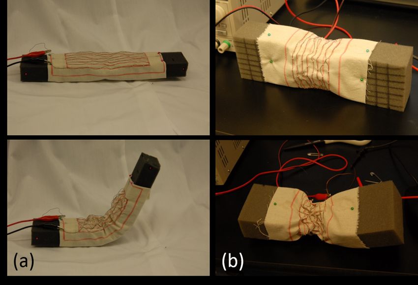
The sensors, hereby referred to as sensor threads, consist
of hyperelastic tubing (High Purity White Silicone Tubing,
McMaster-Carr, outer diameter 0.037”) filled with eutectic
gallium indium (eGaIn), a non-toxic conductive liquid alter-
native to mercury (Figure 3a). A length of silicone tubing is
first filled with eGaIn by injecting it through the tubing with
a syringe. Copper wire is inserted into the ends of the sensors
to serve as lead wires. The sensors are sealed by encasing
silicone caulk at the wire-tubing interface with heat shrink
tubing. After allowing the caulk to cure, heat is applied to
the heat-shrink tubing to complete the sealing process.
   The sensor thread is secured onto the fabric base by
couching the heat shrink tubing onto the fabric as shown
in Figure 3b. Couching is a method of securing a yarn
onto a fabric by stitching another thread around the yarn,
harnessing the yarn to the fabric. Only the ends of the sensor
threads covered with heat shrink tubing are couched onto the
fabric to prevent the thread from compressing the silicone               Fig. 4: Characterization of linear force generation by a single
tubing and provoking a false report of strain. The sensors               actuator unit using a materials testing machine.
and SMA are attached on opposite sides of the fabric to
reduce the possibility of damaging the tubing through heating                         10
or pinching when the SMA is activated. The sensors are
pretensioned with approximately 60% strain when attaching                              8
them to the fabric base such that the sensor experiences zero
                                                                                       6
strain when the robotic fabric is fully contracted. As a result,
                                                                           Load (N)

when the fabric is flat, the sensor undergoes a positive 60%                           4
strain.
   Considerations of the robotic fabrics intended geometry                             2
are used to determine the placement, length and orientation
of the sensor threads. For example, to measure the amount of                           0
bending in a body, sensors are laid parallel to the anticipated
direction of bending as shown in Figure 3b. By reading the                            −2
                                                                                        0   200   400   600   800   1000   1200
resistance output of multiple sensors arranged on a body, the                                            Time (s)
deformation and curvature of the body can be obtained.
                                                                         Fig. 5: Plot of the force produced by a single actuator unit
                  IV. C HARACTERIZATION                                  in isometric contraction over 15 cycles. The fabric swatch had
                                                                         dimensions 2.625” x 6” and contained 8 returns of programmed
A. Actuator Characterization                                             SMA spaced 0.375” apart. SMA was powered at 10V and 1.2A.
   In order to characterize the performance of SMA inte-
grated in the fabric for linear isometric force generation, we
fabricated a rectangular swatch with dimensions 2.625” x 6”              generated by the actuation unit, for which the total length of
containing 8 returns of SMA spaced 0.375” apart. The length              SMA was 50.625”, was approximately 9.6N. When allowed
of the swatch was maintained constant between the jaws of a              to freely contract, the fabric contracted approximately 60% in
materials testing machine (Instron 3345) (Figure 4). The unit            length. This linear force and displacement may be translated
was actuated by a power supply outputting a constant 10V                 to bulk radial pressure when the fabric is wrapped around a
and a maximum of 1.2A, prompting the SMA to recall its                   host. While a rough estimate may be obtained by assuming
programmed shape, a helical coil of diameter 0.25”. Because              that the stress in the actuator is linearly proportional to the
the length of the unit was maintained constant, an increase              hoop stress (as given by pressure vessel analysis), actual
in force was measured.                                                   distributed pressure will depend largely on properties of the
   The force was recorded over 15 cycles of powering the                 host such as size, shape, elasticity, and compressibility.
SMA on and off at 10V and 1.2A over 30s and 60s time
intervals, respectively (Figure 5). The actuator unit was found          B. Sensor Characterization
to degrade in performance in terms of force production                      To determine the sensor threads resistive response to
by 9.8% after 5 cycles and 17.4% after 15 cycles due to                  strain, an Instron materials testing machine was used to
degradation of the shape memory effect of the SMA, as well               apply strain to the device at a rate of 50mm/min from
as stretching of the base fabric and stitching thread. It is             0 to 100%. Simultaneously, a BK Precision 5492B digital
assumed that the degradation will continue due to weak-                  multimeter recorded the resistance at a rate of 2Hz. As
ening of the fabric and stitch threads. The maximum force                the sensors are stretched, the cross-section decreases and

                                                                   582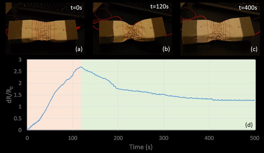
the overall length increases. This results in an increase in                This is demonstrated in the plot of dR/R0 in Figure 7, where
                      L
resistance as R = ρ A   , where ρ is the resistivity of eGaIn,              the output resistance decreases as the joint angle decreases.
L and A are the length and cross-sectional area of the                      Characterization of the sensor threads focused solely on the
sensor, respectively. The experimental data relating strain to              response due to linear strain (Figure 6). To translate linear
the normalized change in resistance of the sensor (dR/R0 )                  strain to proprioceptive capability in a bending application,
was plotted to determine the characteristic behavior of each                the joint angle can be calculated via the law of cosines as θ =
                                                                                      2  2
                                                                                           −L2
sensor (Figure 6).                                                          arccos( a +b2ab    ), where a and b are the distances between
                                                                            the ends of the sensor and the axis of rotation and L is the
        2.5                                                                 length of the sensor. Length L is calculated by applying the
              Sensor 1
              Sensor 2                                                      empirically found linear model to the normalized resistance
         2    Sensor 3                                                      output of the sensor due to applied strain.
              Sensor 4
              Sensor 5                                                         To empirically verify proprioceptive capability, the output
        1.5
              Sensor 6                                                      of a sensor thread was recorded at various joint angles from
dR/R0

         1                                                                  approximately 90◦ to 180◦ . The sensor was attached to the
                                                                            arms of the joint while the joint angle was 180◦ with a pre-
        0.5                                                                 strain of 60%; at 90◦ , the distance between the attachment
                                                                            points was slightly less than the initial length of the sensor.
         0                                                                  The actual joint angle was determined by measuring the
          0          20     40           60       80         100            angle in photos taken directly from the side during the test.
                                 Strain (%)                                 The empirical calibration demonstrated a linear relationship
Fig. 6: Resistive response of 6 sensor threads of the same geometry         between the joint angle and the normalized resistance, which
to applied strain at a rate of 50mm/min. Data has been smoothed             is consistent with the linear characterization reported in
by a running average over 10 data points.                                   Figure 6. Analysis of the calibration data yielded the re-
                                                                            gression equation: θ = 108.46 dRR0 + 103.61, which was used
   Figure 6 plots the response of 6 individual threads of the               to calculate the expected joint angle given a normalized
same dimensions (outer dia. 0.037”, length 5”). While the                   resistance value. A comparison of the actual and expected
strain characterization data appears to follow a 2nd-order                  joint angle given a normalized resistance output is plotted in
polynomial model, within the range of 0 to 100% strain, the                 Figure 8. The RMS error between the actual and expected
data can also be approximated by a linear model. Although                   joint angle was found to be 14.6%. At low bend angles, the
plotted outputs are normalized by the initial resistance of                 accuracy of the sensor degrades because the sensor was slack
each sensor by dR/R0 , the responses are clearly inconsistent               and had a near-zero normalized resistance output. Once out
across different specimens of the same design specifications.               of this range (approximately 115-120◦ ), the accuracy of the
This implies imperfections in the manufacturing process (e.g.               sensor improved due to sufficient tension across the sensor.
sealing, wire-eGaIn interface) that must be addressed for                   To increase the range of angles that can be measured, more
consistent product yield and the need for individual empirical              sensors can be placed around the joint and different methods
characterization of each sensor.                                            of sensing can be used.
                          V. R ESULTS
A. Bending                                                                  B. Compression
   Robotic fabric was pinned across a hinge joint in a foam                    The same swatch of robotic fabric was wrapped around
block such that during activation, the fabric would remain                  and then pinned to a foam block with the sensor thread be-
secured to the surface of the foam block, thus causing the                  tween the fabric and the foam (Figure 9). The SMA was acti-
arms to bend together (Figure 7). The SMA was powered at                    vated with 10V and 1.2A for 2 minutes then deactivated; the
a constant voltage of 10V and a maximum current of 1.2A                     resistance output of the sensor was continuously recorded.
for 50s, which ensured that the SMA would reach maximal                     In contrast to the bending application, the resistance of the
force production as seen in Figure 5. The force produced was                sensor increased as the SMA was activated. As the fabric
sufficient to decrease the joint angle by approximately 80◦ .               squeezed the foam, it also applied pressure to the sensor.
After the power to the actuation unit was turned off, the foam              Because the resistance of the sensor thread is R = ρL   A , the
body and the fabric were allowed to relax to a final state.                 decrease in cross-sectional area, A, results in an increase
Because the foam block did not provide sufficient rebounding                in resistance, R. The effect of pressure on this device has
force, the SMA remained in a semi-contracted state and the                  not yet been conclusively characterized; however, previously
joint remained slightly bent.                                               developed elastomer-based pressure sensors operate on this
   The joint angle can be approximated from the sensory                     basic principle [24], [25]. The resistance increased somewhat
data. Because the sensor is pretensioned when attaching it to               linearly up to the maximum compression, at which point the
the fabric, it experiences maximal strain when the joint angle              SMA was deactivated. As the SMA cooled, it maintained a
is 180◦ , i.e. when the fabric is flat. As the joint is flexed due          semi-contracted state due to an insufficient restoring force to
to contraction of the SMA, the sensor experiences less strain.              decompress the foam and re-extend the SMA wire.

                                                                      583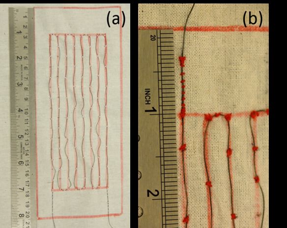
Fig. 7: (a)-(c) Photos of a bending application showing the initial state, the maximum bending position, and the final relaxed state. (d)
Sensor output during flexure of a joint. The red and green shading indicate powered and unpowered SMA, respectively. Data has been
smoothed by averaging over 10 data points.

                      200                                                    that are typically associated with bending of a spine or the
                                                                             bending of an articulated limb, and many traditional robotics
                      180                                                    applications have been developed [26], [27], [28]. Robotic
 Actual Joint Angle

                                                                             fabric may have applications in traditional robotic settings,
                      160                                                    as there is a need for softer and safer robots in industry and
                                                                             in human environments. Soft and partially articulated bodies
                      140
                                                                             could bend and function effectively like an articulated limb as
                      120                                                    the robotic fabric matrix acts effectively like the antagonist
                                                                             pairs of muscles that occur across joints. To assist motion
                      100                                                    of a human wearer, fabric that spans articulated joints could
                                                                             generate additional bending moments beyond what a human
                       80                                                    achieves with his or her own muscles. Such robotic fabric
                        100   120      140       160       180   200
                                    Expected Joint Angle                     spanning across a human joint would act like an additional
Fig. 8: Comparison of actual and expected joint angles. The                  thin layer of muscle on top of the musculoskeletal complex
                                                      dR                     of the joint.
expected joint angle was calculated from θ = 108.46 R  0
                                                         + 103.61
as determined during prior empirical sensor calibration.                        When the robotic fabric is attached to a foam block
                                                                             such that the active threads act around the circumference,
                                                                             it produces a net pressure on the surface of the body that
                                    VI. D ISCUSSION                          causes a compressive deformation. The compression of a
   When the robotic fabric is attached to a face of the body                 circumferential robotic fabric has immediate relevance for
such that the active threads act more on one side of the                     robotics applications ranging from wearable compression
body than another, bending occurs. Even if robotic fabric is                 suits to soft-bodied locomotion like peristalsis (e.g. earth-
attached on all sides or faces of a body and co-activation                   worm locomotion) [21], [22], [23]. To achieve a wearable
occurs, if there is net actuation to one side of the body,                   and active compression garment, active threads would be
then bending occurs to that side. The bending motion of                      oriented around the circumference of limbs and the trunk
a soft body can also be approximated by bending beam                         of the human body. This would enable the control of static
theory, lending itself to fundamental analysis and predictive                pressure and cyclic pressure over desired portions of limbs
modeling.                                                                    and the trunk.
   Bending is a fundamental mode of motion with many ap-                       Although the current sensing capabilities of robotic fabric
plications for robotics. Bending is representative of motions                cannot be relied upon for their quantitative accuracy, their

                                                                       584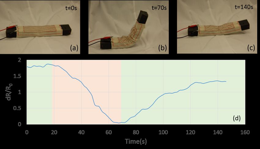
Fig. 9: (a)-(c) Photos of a compression application showing the initial uncompressed state, the maximum compression achieved, and the
final semi-decompressed state. (d) Sensor output during compression of a foam block. The red and green shading indicate powered and
unpowered SMA, respectively.

responses provide qualitative proprioceptive feedback. In the             Introducing multiple sensor threads into a robotic fabric
bending application, the robotic fabric was placed on the              would yield richer sensory information. Not only would
inside of the joint to cause flexion. As a result, the sensor          the resolution of the sensory output increase, values such
decreased in resistance as the joint was flexed because the            as the curvature of the host body could be determined.
sensor was less strained (Figure 7). A set of two sensors can          By combining knowledge of the host body and differential
thus be used, at a minimum, to qualitatively differentiate             curvature sensing techniques, the overall curvature of the
between directions of flexion of a joint. Conversely, in the           body can be found. Furthermore, the manufacturing methods
compression application, the robotic fabric was wrapped                currently used can be improved towards goals of increased
around a foam block and the sensor increased in resistance             repeatability and robustness. More specifically, more robust
as the foam was compressed (Figure 9). In both applications,           sealing methods and elimination of air bubbles in the elas-
the robotic fabric contracted, whereas the sensor responses            tomer tubing used for the sensors should be pursued.
were opposite. Bending and compression can be clearly                     In terms of wearability of the robotic fabric, safety
differentiated and qualitatively correlated with the sensor            concerns will have to be studied. Because the transition
output.                                                                temperature of the SMA wire used here is 70◦ C, continuous
                                                                       powering of SMA may generate enough thermal energy to
                    VII. F UTURE W ORK                                 burn the skin during sustained direct contact, depending on
   The active and sensing thread components of the robotic             the duration of contact and the temperature of the contacting
fabric can be readily integrated using existing textiles tech-         object. The threshold temperature for causing minor acute
nology and methods. In this work, both SMA wire actuators              skin burns after 30s exposure is 48.4◦ C [29]; currently,
and elastomeric sensors were sewn into the fabric by either            the maximal temperature on back of the robotic fabric will
hand-sewing or use of a sewing machine. In the future, these           reach 50◦ C as measured by a thermocouple (Fluke 87V
components may also be woven into a fabric.                            temperature probe) after a 30s actuation period at 10V
   Investigating the interaction between the SMA wire and              and 1.2A. Implementing conservative powering sequences,
the fabric, as well as the choice of textile and thread could          adding layers of thermal insulation and introducing other
improve the performance of the actuation unit as a whole.              thermal management mechanisms will minimize the skin
Also, the programming of the SMA can be optimized to im-               contact temperature.
prove shape fixity. Control and powering of the SMA can be
more precisely regulated to reduce damage to the crystalline                               VIII. C ONCLUSION
structure of the austenite phase and reduce degradation of               In this paper, we have demonstrated how a single sheet
the shape memory effect.                                               of robotic fabric can be used to generate multiple motion

                                                                 585
and sensing functions depending on how it is applied to a [9] A. Grillet, D. Kinet, J. Witt, M. Schukar, K. Krebber, F. Pirotte, and
host body. In particular, we demonstrated that compression A. Depré, “Optical fiber sensors embedded into medical textiles for
healthcare monitoring,” Sensors Journal, IEEE, vol. 8, no. 7, pp. 1215–
and bending motion can be achieved. These two modes of 1222, 2008.
motion are representative of basic motions for a range of [10] M. Pacelli, L. Caldani, and R. Paradiso, “Textile piezoresistive sensors
robotic applications ranging from wearable robots to new for biomechanical variables monitoring,” in Engineering in Medicine
and Biology Society, 2006. EMBS’06. 28th Annual International
soft industrial robots to autonomous soft robots. Conference of the IEEE. IEEE, 2006, pp. 5358–5361.
We discussed the fabrication methods and characterization [11] M. Hamedi, L. Herlogsson, X. Crispin, R. Marcilla, M. Berggren, and
of the actuation and sensing components of robotic fabric. O. Inganäs, “Fiber-embedded electrolyte-gated field-effect transistors
for e-textiles,” Advanced Materials, vol. 21, no. 5, pp. 573–577, 2009.
The SMA wire actuator was programmed into a helical coil, [12] J. B. Lee and V. Subramanian, “Organic transistors on fiber: a first
then unwound and sewn onto a muslin base fabric in a step towards electronic textiles,” in Electron Devices Meeting, 2003.
serpentine pattern. Although increasing the number of returns IEDM’03 Technical Digest. IEEE International. IEEE, 2003, pp. 8–3.
[13] R. Liu, S. Wang, and T. T. Lao, “A novel solution of monitoring
of SMA on the fabric could increase the contractile force, incontinence status by conductive yarn and advanced seamless knitting
interactions between the base fabric, stitch thread, and SMA techniques.” Journal of Engineered Fabrics & Fibers (JEFF), vol. 7,
will also play a role in the resulting force production. no. 4, 2012.
[14] A. Drimus, G. Kootstra, A. Bilberg, and D. Kragic, “Classification of
The sensor threads are composed of eGaIn-filled silicone rigid and deformable objects using a novel tactile sensor,” in Advanced
tubing. Due to inconsistencies in manufacturing, the response Robotics (ICAR), 2011 15th International Conference on. IEEE, 2011,
of the sensors are currently non-uniform across different pp. 427–434.
[15] T. Kannaian, R. Neelaveni, and G. Thilagavathi, “Development and
samples. As a result, each thread is currently characterized characterisation of elastomeric tape sensor fabrics for elbow angle
individually. However, the sensors can reliably qualitatively measurement,” Indian Journal of Fibre and Textile Research, vol. 36,
differentiate between the compressive and bending motions no. 4, p. 436, 2011.
[16] T. Kaufmann and C. Fumeaux, “Wearable textile half-mode substrate-
demonstrated by yielding increased and decreased dR/R0 , integrated cavity antenna using embroidered vias,” Antennas and
respectively. Wireless Propagation Letters, IEEE, vol. 12, pp. 805–808, 2013.
The integration of actuator threads and sensor threads into [17] J. B. Lee and V. Subramanian, “Weave patterned organic transistors on
fiber for e-textiles,” Electron Devices, IEEE Transactions on, vol. 52,
a robotic fabric was also demonstrated, and future integration no. 2, pp. 269–275, 2005.
could include higher numbers of each thread. Having a [18] E. Bonderover and S. Wagner, “A woven inverter circuit for e-textile
single robotic fabric with actuators and sensors integrated applications,” Electron Device Letters, IEEE, vol. 25, no. 5, pp. 295–
297, 2004.
throughout would provide general purpose functionality, and [19] S.-I. Vasile, K. E. Grabowska, I. L. Ciesielska-Wrobel, and J. Ghitaiga,
enable new programmable fabrics. “Analysis of hybrid woven fabrics with shape memory alloys wires
embedded,” FIBRES & TEXTILES IN EASTERN EUROPE, 2010.
Overall, the introduction of robotic fabrics is expected [20] R. Paradiso, A. Gemignani, E. Scilingo, and D. De Rossi, “Knit-
to contribute towards new exciting possibilities for highly ted bioclothes for cardiopulmonary monitoring,” in Engineering in
wearable and conformable robots, as well as general soft Medicine and Biology Society, 2003. Proceedings of the 25th Annual
International Conference of the IEEE, vol. 4. IEEE, 2003, pp. 3720–
robots. 3723.
[21] Y.-L. Park, B.-r. Chen, D. Young, L. Stirling, R. J. Wood, E. Goldfield,
R EFERENCES and R. Nagpal, “Bio-inspired active soft orthotic device for ankle
foot pathologies,” in Intelligent Robots and Systems (IROS), 2011
[1] S. Kim, E. Hawkes, K. Choy, M. Joldaz, J. Foleyz, and R. Wood,
IEEE/RSJ International Conference on. IEEE, 2011, pp. 4488–4495.
“Micro artificial muscle fiber using niti spring for soft robotics,” in
[22] M. Wehner, B. Quinlivan, P. M. Aubin, E. Martinez-Villalpando,
Intelligent Robots and Systems, 2009. IROS 2009. IEEE/RSJ Interna-
M. Bauman, L. Stirling, K. Holt, R. Wood, and C. Walsh, “Design and
tional Conference on. IEEE, 2009, pp. 2228–2234.
evaluation of a lightweight soft exosuit for gait assistance,” in 2013
[2] E. R. Post and M. Orth, “Smart fabric, or,” in Wearable Computers,
IEEE International Conference on Robotics and Automation (ICRA),
1997. Digest of Papers., First International Symposium on. IEEE,
2013, pp. 6–10.
1997, pp. 167–168.
[23] S. Seok, C. D. Onal, R. Wood, D. Rus, and S. Kim, “Peristaltic
[3] J. Farringdon, A. J. Moore, N. Tilbury, J. Church, and P. D. Biemond, locomotion with antagonistic actuators in soft robotics,” in Robotics
“Wearable sensor badge and sensor jacket for context awareness,” in and Automation (ICRA), 2010 IEEE International Conference on.
Wearable Computers, 1999. Digest of Papers. The Third International IEEE, 2010, pp. 1228–1233.
Symposium on. IEEE, 1999, pp. 107–113. [24] Y. Park, C. Majidi, R. Kramer, P. Bérard, and R. Wood, “Hypere-
[4] D. Bowman and B. Mattes, “Conductive fibre prepared from ultra-high lastic pressure sensing with a liquid-embedded elastomer,” Journal of
molecular weight polyaniline for smart fabric and interactive textile Micromechanics and Microengineering, vol. 20, p. 125029, 2010.
applications,” Synthetic metals, vol. 154, no. 1-3, pp. 29–32, 2005. [25] R. Kramer, C. Majidi, and R. Wood, “Wearable tactile keypad with
[5] A. Lymberis and R. Paradiso, “Smart fabrics and interactive textile stretchable artificial skin,” in Robotics and Automation (ICRA), 2011
enabling wearable personal applications: R&d state of the art and IEEE International Conference on. IEEE, 2011, pp. 1103–1107.
future challenges,” in Engineering in Medicine and Biology Society, [26] G. Mennitto and M. Buehler, “CARL: a compliant articulated robot
2008. EMBS 2008. 30th Annual International Conference of the IEEE. leg for dynamic locomotion,” Robotics and autonomous systems, 1996.
IEEE, 2008, pp. 5270–5273. [27] L. Roos, F. Guenter, A. Guignard, and A. G. Billard, “Design of
[6] M. Pacelli, G. Loriga, N. Taccini, and R. Paradiso, “Sensing fabrics a biomimetic spine for the humanoid robot robota,” in Biomedical
for monitoring physiological and biomechanical variables: E-textile Robotics and Biomechatronics, 2006. IEEE, 2006, p. 329334.
solutions,” in Medical Devices and Biosensors, 2006. 3rd IEEE/EMBS [28] I. Mizuuchi, R. Tajima, T. Yoshikai, D. Sato, K. Nagashima, M. Inaba,
International Summer School on. IEEE, 2006, pp. 1–4. Y. Kuniyoshi, and H. Inoue, “The design and control of the flexible
[7] D. Marculescu, R. Marculescu, N. H. Zamora, P. Stanley-Marbell, P. K. spine of a fully tendon-driven humanoid,” in Intelligent Robots and
Khosla, S. Park, S. Jayaraman, S. Jung, C. Lauterbach, W. Weber et al., Systems, 2002. IEEE/RSJ, vol. 3. IEEE, 2002, p. 25272532.
“Electronic textiles: A platform for pervasive computing,” Proceedings [29] P. S. Yarmolenko, E. J. Moon, C. Landon, A. Manzoor, D. W.
of the IEEE, vol. 91, no. 12, pp. 1995–2018, 2003. Hochman, B. L. Viglianti, and M. W. Dewhirst, “Thresholds for
[8] M. A. El-Sherif, J. Yuan, and A. Macdiarmid, “Fiber optic sensors and thermal damage to normal tissues: An update,” Int J Hyperthermia,
smart fabrics,” Journal of intelligent material systems and structures, vol. 27, no. 4, pp. 320–343, 2011.
vol. 11, no. 5, pp. 407–414, 2000.
586You can also read