3D Transparent Object Detection and Reconstruction Based on Passive Mode Single-Pixel Imaging - MDPI
←
→
Page content transcription
If your browser does not render page correctly, please read the page content below
sensors
Article
3D Transparent Object Detection and Reconstruction
Based on Passive Mode Single-Pixel Imaging
Anumol Mathai 1 , Ningqun Guo 1 , Dong Liu 2 and Xin Wang 1, *
 1    School of Engineering, Monash University Malaysia, Jalan Lagoon Selatan, Bandar Sunway,
      Selangor 47500, Malaysia; anumol.mathai@monash.edu (A.M.); anthony.guo@monash.edu (N.G.)
 2    State Key Laboratory of Modern Optical Instrumentation, College of Optical Science and Engineering,
      Zhejiang University, 38 Zheda Road, Hangzhou 310027, China; liudongopt@zju.edu.cn
 *    Correspondence: wang.xin@monash.edu

 Received: 30 May 2020; Accepted: 24 July 2020; Published: 29 July 2020

 Abstract: Transparent object detection and reconstruction are significant, due to their practical
 applications. The appearance and characteristics of light in these objects make reconstruction methods
 tailored for Lambertian surfaces fail disgracefully. In this paper, we introduce a fixed multi-viewpoint
 approach to ascertain the shape of transparent objects, thereby avoiding the rotation or movement of
 the object during imaging. In addition, a simple and cost-effective experimental setup is presented,
 which employs two single-pixel detectors and a digital micromirror device, for imaging transparent
 objects by projecting binary patterns. In the system setup, a dark framework is implemented around
 the object, to create shades at the boundaries of the object. By triangulating the light path from the
 object, the surface shape is recovered, neither considering the reflections nor the number of refractions.
 It can, therefore, handle transparent objects with a relatively complex shape with the unknown
 refractive index. The implementation of compressive sensing in this technique further simplifies
 the acquisition process, by reducing the number of measurements. The experimental results show
 that 2D images obtained from the single-pixel detectors are better in quality with a resolution of
 32 × 32. Additionally, the obtained disparity and error map indicate the feasibility and accuracy of
 the proposed method. This work provides a new insight into 3D transparent object detection and
 reconstruction, based on single-pixel imaging at an affordable cost, with the implementation of a few
 numbers of detectors.

 Keywords: transparent object detection; single-pixel imaging; compressive sensing; disparity
 map acquisition

1. Introduction
     Many practical activities in industry, such as automatic inspection, oceanology, fluid mechanism,
and computer graphics, often require imaging of three-dimensional shapes of invisibles. Though
various techniques have been developed for deducing 3D images of transparent objects, this class
of objects poses difficulties due to many reasons. Firstly, these objects are colorless, and they gain a
form from neighboring background objects. Secondly, the complexity of light interactions within the
transparent objects makes its detection impossible. Finally, knowledge about the refractive index of
the material is needed for reconstruction.
     The existing techniques for transparent object inspection required application of known or unknown
background (checkboard/striped) patterns in calibration with a camera, which is computationally a
long process and costly. The first implementation of an unknown background pattern at the bottom
of the water tank was performed to approximate the distorted water surface. Thereafter, structured
light patterns were introduced to extract the surface properties of the glass objects [1]. Subsequently,

Sensors 2020, 20, 4211; doi:10.3390/s20154211                                    www.mdpi.com/journal/sensors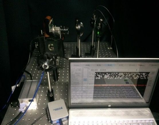
Sensors 2020, 20, 4211                                                                               2 of 13

direct rays were collected from the refractive objects by placing multiple cameras in several positions,
with respect to the object to approximate the depth [2]. Later, the shape of transparent objects was
reconstructed from its known motion [3]. Dusting and submerging transparent objects in fluorescent
liquids deteriorated the structure of the object, therefore, it has limited its implementation in real-time
applications [4,5]. Presently, transparent object recovery is achieved by combining polarization analysis
and light-path triangulation [6]. Almost all the techniques for depth acquisition rely on some external
factors, such as system calibration, background patterns, less intensity environment, and object motion,
which will introduce a lot of errors to the inspection system. Hence, the accuracy is relatively low.
      In addition, a range of sensors, such as color cameras, light detection and ranging (LIDAR)
systems, time of flight (TOF) cameras, IR cameras and Kinect sensors, have been developed to image
transparent objects, yet a general solution could not find for the detection of transparent objects [7–9].
In color cameras, object recognition can be performed when the background color of the object is
exactly the same as the color of the object. When LIDAR/TOF sensors are used to image a transparent
object, the reflected light from the object has recorded an approximate shape. The projected light
from these sensors is reflected multiple times before it hits the transparent object, which does not
cause object information in the camera. Hence, the shape cannot be recognized, and the edges of the
object have been missed, which made object reconstruction impossible. Kinect sensor is an alternative
method utilized for transparent object inspection, in which a sensor is moved in the scene to acquire
multiple views of the object [7]. Additionally, the work is limited to non-planar transparent objects
with a smooth surface. With an IR camera, Maldague et al., proposed a technique called “shape
from heating”, in which the transparent object surface was heated with a thermal camera source,
and the time sequence of thermograms (thermal images) was recorded to estimate the shape [10]. Later,
Eren et al. developed “scanning from heating” to detect 3D transparent objects on the basis of “shape
from heating” technique, used by Maldague et al. [11]. In this work, the object was heated with a laser
source, to a temperature at which the object turns opaque and then, irradiations were recorded by a
thermal camera for shape estimation. The main limitations of these studies were the non-uniform
surface heating of the object and the use of an infrared laser source, which restricted the performance
of both the studies. The identified limitations in the sensors can be solved with an alternative sensor
called a “single-pixel detector”.
      Single-pixel imaging (SPI) is an advanced imaging approach that is applicable for acquiring spatial
information in low light, high absorption, and backscattering conditions [12]. SPI has been widely used
in myriad applications, such as infrared imaging [13], gas imaging [14], photoacoustic imaging [15],
three-dimensional imaging [16–18], terahertz imaging [19,20], X-ray diffraction tomography [21],
remote sensing [22], encrypted imaging [23], lensless imaging [24], shadowless imaging [25],
hyperspectral imaging [26], microscopy [27], and scattering imaging [28]. In this imaging modality,
a single-pixel detector that has no spatial resolution can detect the object by means of a modulated
structured light [29]. Though this imaging technique is affected by noises, the ability to work in
challenging environments with high resolution and precision enables single-pixel detection more
popular than any other conventional imaging systems [30]. Moreover, its sensitivity to a wide operating
spectrum extends its operation range beyond the visible spectrum [31]. All these characteristics
of single-pixel imaging have been utilized to recover the images from challenging environments.
The smart control of light propagation with prior knowledge of the modulated patterns in this technique
moderates the depletion of the ballistic photons. Tajahuerce et al. proposed an optical system using a
single-pixel camera, which can successfully reconstruct 2D objects, even under multiple scattering
conditions in turbid media [28]. In addition, this work compared the quality of 2D image reconstruction
with the result of CCD camera. In the presence of a scattering medium in front of the object, a CCD
camera can only capture the speckle pattern (no information regarding the object). On the contrary,
a single-pixel detector can record an excellent result. Based on the modulation involved, this technique
is classified as active and passive single pixel imaging. Both methods are implemented in many
imaging modalities for the acquisition of 2D and 3D objects.
Sensors 2020, 20, 4211                                                                                3 of 13

      Magalhães et al. presented an active illumination single-pixel camera, in which a photodetector
approximated a replica of the object by averaging the inner product between the pattern and the object
sample [32]. The problem of spatial and temporal aberrations that occurs in imaging transparent object
was resolved in [12]. Later, Bertolotti et al. [33] proposed a non-invasive imaging technique that uses
an iterative algorithm to retrieve the image of a fluorescent object hidden in the opaque medium.
There are many published works on non-line of sight imaging, in which the object is sandwiched
between two layers of chicken pieces with a thickness of 2.84 mm and 2.92 mm [34,35]. The imaging
has performed using a single-pixel detector and estimated the image of the sandwiched object. Winters
et al. recommended a method to improve the speed of reconstruction in scattering media with the
help of help of x and y modulators. These modulators can operate at extremely high speed control the
illumination pattern before sampling the object [36]. All the above-mentioned works give an insight
into the reconstruction of 2D objects.
      Three-dimensional image reconstruction approaches, such as time-of-flight (TOF), binocular
vision, photometric stereo, and shape-from-X techniques can estimate the depth information of opaque
objects. Sun et al. [37] proposed a model based on the “shape from shading” method, where multiple
cameras were placed at different positions of the reflective object. Two-dimensional images from each
camera hold the shadows of the object from which surface gradients are derived and 3D images are
reconstructed via photometric stereo. Wen-kai et al. [38] developed a 3D reconstruction system using
a binocular stereo vision algorithm and a single-pixel detector by placing the object on a rotating
platform. The limitations of using spatially separated multiple detectors and moving the object were
eliminated in [17]. The TOF technique is utilized to obtain the depth information and its accuracy
depends on a high-speed photodiode and precision in measurements. Similarly, other demonstrations
for scanning the scene and obtaining the depth and reflectivity information via TOF have also been
discussed [39–42]. Zhang et al. proposed a method to capture the images of opaque objects. In this
study, four photodetectors were implemented at different locations of the object to capture the reflected
light. The variations in shading information in the images were studied, and a photometric stereo
algorithm was utilized for 3D image reconstruction [43]. Salvador-Balaguer et al. [44] implemented a
basic active single-pixel imaging system to image opaque objects. They also used reflected light from the
object and processed it, based on an adaptive compressive algorithm for image reconstruction. All these
methods are suitable for recovering 3D images of objects for reflective surfaces. The perfect assembly
and tuning of all instruments with high precision are needed to achieve the target reconstruction.
If the relevant parameters of each instrument in the system are properly raised, and the high-precision
assembly is matched, all these techniques can assure the overall reconstruction quality of the system.
      In this paper, we present a fixed multi-viewpoint 3D transparent object inspection system, based on
passive mode single-pixel imaging. Two single-pixel detectors are applied in the setup to eliminate
the need to move the object while imaging. The results show that it is possible to obtain the disparity
map of the object by using high-speed detectors to record the sampled refracted light, along with our
image reconstruction algorithm. The rest of the paper is organized as follows. Section 2 describes our
experimental setup for 3D transparent object detection. Section 3 examines how 3D depth information
is extracted from 2D images. This is followed by the conclusion, which is expounded in Section 4.

2. Experimental Setup
     The schematic diagram of the proposed 3D transparent object detection system is shown in the
Figure 1. The system consists of a red laser to illuminate the transparent object, a dark framework to cause
streak effects at the object boundary, an imaging lens, a digital micromirror device (DMD) to modulate
the laser light with a computer-generated measurement matrix, collecting lenses, two single-pixel
detectors to collect the transmitted light from the object, a data acquisition (DAQ) system, and a
computer, to perform 2D and 3D image reconstruction.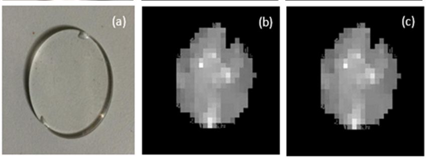
Sensors 2020, 20, x4211
FOR PEER REVIEW 44 of
of 13
13
Sensors 2020, 20, x FOR PEER REVIEW 4 of 13
Figure 1. Schematic of 3D transparent object detection and disparity map acquisition system. The red
Figure1.1.Schematic
Figure Schematicofof3D3Dtransparent
transparentobject
objectdetection
detectionand
anddisparity
disparitymap
mapacquisition
acquisitionsystem.
system.The
Thered
red
dashed
dashed line indicates the laser light beam from the source to detectors.
dashedline
lineindicates
indicatesthe
thelaser
laserlight
lightbeam
beamfrom
fromthe
thesource
sourcetotodetectors.
detectors.
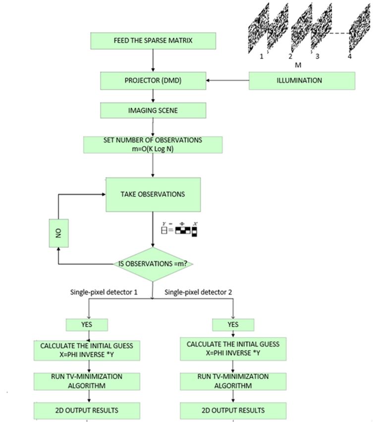
The
The experimental
experimental set set up
upisisshown
shownin inthe
theFigure
Figure2.2.The Thefiber
fiberoutput
outputred redlaser
laser (650
(650nm,nm, 1W)1 W)is to
is
The experimental set up is shown in the Figure 2. The fiber output red laser (650 nm, 1W) is to
illuminate
to illuminate thethetarget
targetobject.
object. TheThe refracted
refracted light
lightfrom
fromthe thetarget
targetisiscollected
collectedby by anan imaging
imaging lens lens
illuminate the target object. The refracted light from the target is collected by an imaging lens
(LA1740,
(LA1740, f-85 f-85mm)
mm) and anddirected
directedtoto DMD DMD micromirror
micromirror (DMD6500
(DMD6500 &9000) &9000)
activeactive
area. To area. To provide
provide spatial
(LA1740, f-85mm) and directed to DMD micromirror (DMD6500 &9000) active area. To provide
spatial information
information to the to the captured
captured image, image,
the the pre-programmed
pre-programmed patterns patterns
stored in stored
the DMD in the
is DMD is
combined
spatial information to the captured image, the pre-programmed patterns stored in the DMD is
combined
with with the transmitted
the transmitted Then,light. Then, the lightmodulated light from the DMDto is the
projected to the
combined with the light.
transmitted the modulated
light. Then, the modulatedfrom the DMD
light is projected
from the DMD is environment,
projected to the
environment,
where where
two focusing two focusing lenses collect the light and the light is focused to the active area of
environment, wherelenses collect the
two focusing lightcollect
lenses and the thelight
lightisandfocused to the
the light active area
is focused to theof the spatially
active area of
the spatiallysingle-pixel
unresolved unresolveddetectors.
single-pixel Thedetectors. The pre-programmed
pre-programmed patterns in thepatternsexperiment in the experiment
the spatially unresolved single-pixel detectors. The pre-programmed patterns in provide spatial
the experiment
provide
informationspatial information
to the transmitted to the transmitted
light. light.
The experimental The experimental setup is employed for passive
provide spatial information to the transmitted light. Thesetup is employed
experimental setupfor passive modulation
is employed for passive
modulation
mode where mode
two where twophotodetectors
PDA36A2- PDA36A2- photodetectors
are used as are used asdetectors
single-pixel single-pixel to detectors
record to record
the total light
modulation mode where two PDA36A2- photodetectors are used as single-pixel detectors to record
the total light
intensity from intensity
the from
object. the object. DAQ(USB6001)
DAQ(USB6001) digitizes the digitizes
recorded the
lightrecorded
from light
left and from
right left and right
single-pixel
the total light intensity from the object. DAQ(USB6001) digitizes the recorded light from left and right
single-pixel
detectors, detectors,
and sends itand to sends
a sends it to a computer
computer conducttoto conduct
image2D image reconstruction. The 2D The 2Dquality
image
single-pixel detectors, and it to atocomputer 2D conduct reconstruction.
2D image reconstruction. image
The 2D image
quality
depends depends
on patterns on patterns used
any and any distortions in it deteriorate
the imagethe imageWhile quality. While
quality depends on used
patternsand used distortions in it deteriorate
and any distortions in it deteriorate quality.
the image quality. choosing
While
choosing
the passivethemode,
passive themode, the intensity
intensity transformed transformed
object object information
information is is modulated
modulated with with patterns
patterns in the
choosing the passive mode, the intensity transformed object information is modulated with patterns
in
DMD,the DMD,
which which
will will reduce
reduce the the distance
distance at at which
which modulated
modulated light light
beam beam travels,
travels, thereby
thereby reducing
reducing the
in the DMD, which will reduce the distance at which modulated light beam travels, thereby reducing
the distortion
distortion through
through ambient
ambient light.light.
AnyAny deviations
deviations in pattern
in pattern structure
structure cancanalso alsomaintained
be maintained in
the distortion through ambient light. Any deviations in pattern structure can be also be maintained in the in
the passive
passive method.
method.
the passive method.
DMD Lenses Detectors
DMD Lenses Detectors
Lens
Lens
Object & Dark
Object & Dark
framework
framework
Laser
Laser
DAQ Computer
DAQ Computer
Figure 2. Experimental setup implemented in our lab environment.
Figure 2. Experimental setup implemented in our lab environment.
Figure 2. Experimental setup implemented in our lab environment.
For a single-pixel imaging system, the orientation of the optical components and specifications of
For a often
the lenses single-pixel imaging
play a crucial system,
role the orientation
for ensuring of the
high quality optical
images. componentsthe
Additionally, and specifications
proper selection
For a single-pixel imaging system, the orientation of the optical components and specifications
of
of the lens and its focal length is essential to concentrate the transmitted light beam from theproper
lenses often play a crucial role for ensuring high quality images. Additionally, the object
of the lenses often play a crucial role for ensuring high quality images. Additionally, the proper
selection
to the veryof the lens
small and its
active focal
area length
of the is essential
single-pixel to concentrate
detector. the transmitted
Furthermore, combininglight beam
lenses from
such as
selection of the lens and its focal length is essential to concentrate the transmitted light beam from
the object to the very small active area of the single-pixel detector. Furthermore, combining lenses
the object to the very small active area of the single-pixel detector. Furthermore, combining lenses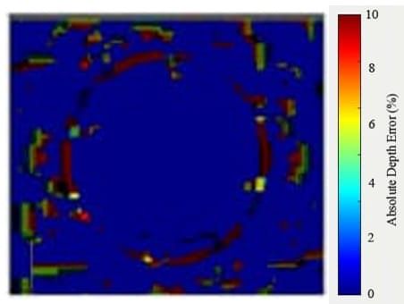
Sensors 2020, 20, 4211                                                                              5 of 13

planar and aspheric ensures sharp focus with fewer aberrations, resulting in better quality 2D images.
As disparity accuracy is closely related to the quality of the 2D reconstruction result, the lens must be
chosen cautiously. The proposed experimental setup is implemented in the lab environment with a
black framework around the sides of the object to provide a streak effect on the edges of the object.
The disparity calculation will depend on the quality of 2D images and edge sharpness. In our work,
transmitted light (majority of the light) is collected for image reconstruction, which will provide good
quality 2D images compared to conventional methods. Moreover, the features of a single-pixel detector,
such as increased detection efficiency, lower noise, and higher time resolution etc., provide additional
advantages. Additionally, the apparent directional illumination from DMD and shadow effect at the
edges of the object make the system superior in producing good quality 2D images. After obtaining
left and right single-pixel detector images, the 3D reconstruction algorithm first looks for the preserved
edges, and then finds out the disparity between the pixels for depth calculation.
      Additionally, calibration of the left and right single-pixel detector images is required to maximize
the accuracy in disparity map calculation, because the 2D images are taken from different angles
of the object. In the calibration process, multiple images of the object are captured from different
perspectives, and self-calibration is performed to obtain the intrinsic and extrinsic parameters for
depth calculation [45,46]. To ensure accurate measurement, the trigger signal is set to initiate the DMD
to modulate the incoming light with preprogrammed patterns. The exposure time and dark time of the
DMD are decided by the number of samples to be recorded for a period. So, the calibration process
reduces the probability of error and consistently increases the measurement process systematically.
      For the experimental setup, two single-pixel detectors are synchronized, such that both the
detectors can capture images at the same time when DMD project patterns. The number of samples to
be recorded is set as 100 in a second for each displayed pattern. DAQ takes an average of 100 samples
to obtain a single measurement that corresponds to each pattern and sends it to a high-performance
computer for further processing. This operation will continue until the DMD stops pattern projection.
In addition, the detectors are placed with a distance of 7 cm between them, to obtain the full view
of the object. The distance from the camera to the object is set as 65 cm, and the focal length of the
single-pixel detector is set as 8.5 cm, which is based on the focal length of the lenses used for focusing
the light on the single-pixel detector.

3. 3D Transparent Object Reconstruction

3.1. 2D Image Reconstruction
     The advent of DMD and single-pixel imaging enables fast image reconstruction with a few
measurements. The transparent object detection and image acquisition process are shown in the
Figure 3. The object to be imaged is fixed at a position and it is scanned and sampled with a sequence
of the sparse matrix (up to M numbers). The resolution of the reconstructed image is decided based on
the resolution and number of the projected sparse matrix. For the following step, the measurements
required for reconstruction is fixed to m (m = O(K log N )), where the total number of pixels in the
object is N, due to the adoption of compressive sensing (CS) in acquiring the samples. The detectors in
the imaging system collect object samples, until DMD stops matrix pattern projection. The number of
patterns projected depends on the sparsity of the measurement matrix. At last, the total variation (TV)
minimization algorithm estimates the original signal X from the measurement vector Y with the prior
knowledge of the sparse matrix. The result obtained from the system is displayed in Figure 4.
Sensors 2020, 20, 4211                                                                                                    6 of 13
          Sensors
 Sensors 2020, 20,2020,
                   x FOR20,PEER
                            x FOR PEER REVIEW
                                REVIEW                                                                                    6 of 13
                                                                                                                    6 of 13

                                    Figure 3. Flowchart of transparent object detection process.
                                         Flowchart
                              Figure3.3.Flowchart
                             Figure               ofof transparent
                                                    transparent    object
                                                                 object    detection
                                                                        detection     process.
                                                                                  process.

                                                (a)                   (b)                     (c)

                                         (a)                    (b)                    (c)

                                                 (a)                  (b)                    (c)

                                         (a)                   (b)                   (c)

      Figure 4.    Two-dimensional
                Figure                 imageimage
                       4. Two-dimensional       reconstruction results
                                                    reconstruction      forfor
                                                                   results  thethe
                                                                                passive
                                                                                   passivesingle-pixel
                                                                                            single-pixelimaging    method.
                                                                                                          imaging method.
                (a) The original object for reconstruction: “G” has a thickness of 10 mm, “bulb” has a size of 20
      (a) The original   object for reconstruction:   “G” has a thickness  of 10 mm,   “bulb”   has  a size of 20 ×  26×mm
                                                                                                                         26
       Figure
      and      4. Two-dimensionalhas
             “Transparent-circle”     image   reconstruction
                                          a thickness   of 5 results
                                                             mm. (b) for The
                                                                         the passive single-pixel
                                                                              reconstructed    2D imaging
                                                                                                    image frommethod.
                                                                                                                   left and
       (a) right
      (c)  The original  object for reconstruction: “G” has a thickness of 10 mm, “bulb” has a size of 20 × 26
                 detectors.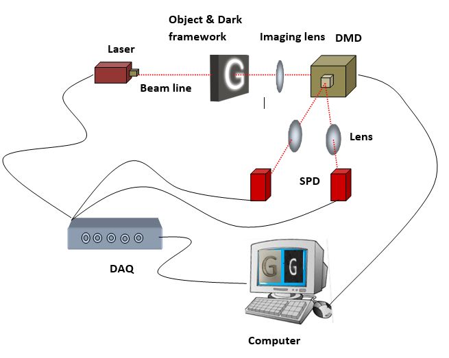
Sensors 2020, 20, 4211                                                                              7 of 13

     Recovering an image, XN×N from a set of measurements vector, YN×N is straightforward with
matrix inversion techniques. With this technique, single-pixel imaging had limitations, such as
the requirement of N2 pixels for reconstruction, long data acquisition time, and large data storage.
These problems can be addressed by combining single-pixel imaging and compressed sensing. It enables
the single-pixel detector to reduce the number of measurements required for reconstruction to YM×1 ,
thereby reducing data storage and data transfer requirements. This method also solves a linear inverse
problem in the case where X has a sparse representation.
     The SPI technique gathers light, which interacts with the object with the aid of a spatially
un-resolved single-pixel detector. The encoding of spatial information in the collected light is done by
the pre-programmed spatially resolved patterns. The single-pixel detector sequentially measures the
inner products between the N × N pixelated scene and a set of M × N binary patterns. The principle
behind the CS imaging is summarized in equation [47]:

                                                  Y = ΦX                                               (1)

where Y is an M × 1 column vector, Φ is the measurement matrix contains, M is the row vector, N is the
column vector, and X is the representation of original image, having N × 1 pixels. When the number of
measurements M in Y is less than the total number of pixels (N ) in X, the Equation (1) will become an
ill-conditioned problem with infinite solutions. To solve such problems, the original image should obey
the property called sparsity, in which only the most significant co-efficients (K-sparse) in the image are
considered for processing, and all the less significant co-efficients are discarded. In CS, the K-sparse
information is acquired and stored in the column vector Y. If an image can be represented in some
basis, then it can be recovered via l1 minimization, with the knowledge of Y and Φ [47].
      Consider a K-sparse signal X and it is sparse in orthogonal basis, Ψ = [Ψ1 , Ψ2 , . . . ΨN ], then

                                                  X = ΨS                                               (2)

where S is K-sparse, in which K coefficients are non-zero. According to CS theory, the signal X an be
recovered with m(m = O(K log N )) incoherent linear measurements when the original signal contains
such K-sparse co-efficients. Then, Equation (1) becomes:

                                             Y = ΦX = ΦΨS                                              (3)

where Φ s a pre-programmed pattern of the size M × N, which is uncorrelated with the sparsity basis
Ψ, and Y is the M × 1 measurement vector [48]. From the measurement vector Y, image recovery is
achieved by the TV-based minimization model. The directional change (gradient) in the object image
X can be determined at a pixel location xij [49]:
                                                               !
                                                    Gh;ij (X)
                                           Gij =
                                                    Gv;ij (X)
                                                                                                       (4)
                                         Gh;ij (X) = xi+1, j − xi,j
                                         Gv;ij (X) = xi,j+1 − xi,j

     The TV minimization algorithm calculates the total variation and removes the undesirable
information by preserving the edges at each pixel location of the image X:
                                             Xq
                                  TV (X) =     Gh;ij (X)2 + Gv;ij (X)2                                 (5)
                                             ij

     TV minimization has been adopted for most image processing fields due to its ability to keep
visual quality than l1 optimization [49]. To acquire the 2D image of the size 32 × 32, the conventional
imaging system would take 1024 measurements. In SPI, 200 measurements, around 20% of the total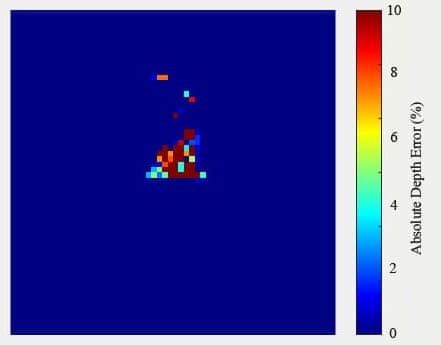
Sensors 2020, 20, 4211                                                                                8 of 13

number of pixels, are used for good quality image reconstruction. Three objects are tested, and the
resultant images reconstructed from the left and right single-pixel detectors are shown in Figure 4.
     Our experimental setup contributes to the formation of good quality 2D images for transparent
objects along with CS algorithm. The 2D image reconstruction quality obtained from the SPI system
is better than the conventional imaging systems, such as LIDAR or TOF cameras [7–9], owing to
single-pixel sensors detection efficiency, lower noise, and higher time resolution. The apparent
directional illumination from DMD and shadow effect at the edges of the object also make the system
superior to traditional imaging methods in obtaining good quality image reconstruction.

3.2. Disparity Map Using Normalized Cross-Correlation (NCC)
     The object in the experimental setup is observed by two single-pixel detectors. This is equivalent to
getting images of the object from two angles without changing the position of it. Binocular stereovision
determines the position of a point in space by finding the intersection of two lines passing through the
center of projection and the projection of point in the image. The images from the two viewpoints
are dissimilar in intensity distribution and the depth information of the images is lost. However,
depth can be inferred through the binocular vision algorithm, which works very similarly to human
eyes. Stereovision algorithms are classified as features based and window/area-based techniques.
Feature based algorithms are complex in finding the matching features for all the edges or corners from
two single-pixel images to build a disparity map. Thus, the area-based method is considered for depth
evaluation, in which the algorithm matches blocks of pixels to find correspondences in the images.
In this study, the NCC method is used to determine the correspondence between two windows around
a pixel of interest. NCC is defined as:

                                                           Xl (i, j).Xr (i0 − d, j0 )
                                                   P
                                                 (i,j)∈w
                           NCC(i, j, d) = r P                                                            (6)
                                                        Xl 2 (i, j).             Xr 2 (i0 − d, j0 )
                                                                         P
                                              (i,j)∈w                  (i,j)∈w

where w is the window size, Xl is the left detector image, Xr is the right detector image, and d is the
disparity. i, j and i0 , j0 are the blocks of pixels to be matched in the left and right detector images,
respectively. The window size can affect the quality of the disparity map, in this work we have chosen
window size as 6 × 6 pixels.
      Three-dimensional image reconstruction quality depends on the quality of 2D images and its edge
sharpness. The complete details about the edge features aid in estimating the boundaries of the object
from the background. Two-dimensional images obtained from SPI are noisy and edges are not uniform.
Hence, background noise has been removed first, and then the canny operator algorithm has been
applied for edge detection. After that, the image is processed using morphological operators to make
the edges smooth and perfect. The major difficulty for transparent object detection is the featureless
surface to compute the disparity. This issue is resolved to some extent in this work, owing to the tracing
of edges and the significant role of the NCC algorithm in depth computation. As the NCC algorithm
is less sensitive to the changes in the intensity value in each pixel, the depth computation with the
algorithm become more precise. Depth information from a pair of images can be calculated by first
computing the distance between the block of pixels at a location in the left image and its corresponding
location in the right image. The search for the best match is performed over a window. This will
produce a disparity map, as shown in Figure 5. Before the disparity calculation, the left and right
images are converted to grayscale images. Hence, the NCC algorithm determines the intensity range
in the images, normally between 0 and 255, and divides the range into multiple offsets (from 0 to 30
offsets), having a range of pixel intensities within each offset. At the same time, the offset adjust is also
calculated using the given formula:
                                                                 255
                                             O f f set ad just =                                          (7)
                                                                  30
Sensors 2020, 20, 4211                                                                              9 of 13

where offset adjust is used in the final step of the algorithm to calculate the pixel range. For NCC
calculation, the left image is fixed, and the right image is moved across the window and intensities
of both left and right images get multiplied and further divided by their own intensity square or
standard deviation of the intensities across the window. Then, the disparity is calculated using the
following equations:
                                            PP
                                      M=             Xl (i, j). ∗ Xr (i0 − d, j0 )
                                             i,j i,j
                                  Xr 2 =         Xr (i0 − d, j0 ). ∗ Xr (i0 − d, j0 )
                                         PP
                                                                                                  (8)
                                         i,j i,j
                                         Xl2 =
                                                   P  P
                                                         Xl (i, j).∗Xl (i, j)
                                                i,j i,j

                                                             M
                                             NCC = q                                                 (9)
                                                           Xr2 ∗ Xl2

where M represents the dot product between the left and right images. The similarity of the pixels
from both left and right images is aggregated over the window size as shown in Equation (6) ariations
in window size will affect the quality of the reconstructed images. Increased window size makes the
disparity map smoother, however, there will be inaccuracies in object detailing at the boundaries. Hence,
smaller window size is chosen to provide maximum depth details with more noise. The obtained
disparity from the above equations is multiplied with the offset value to get the pixel range which is
given by the equation:
                                Disparity map = disparity ∗ o f f set ad just                        (10)

      Depth “z” of the object from the photodetector is calculated using the following formula:

                                                          b× f
                                                   z=                                                (11)
                                                           d
where b represents the baseline distance i.e., the distance from the optical center of one detector to
other, f symbolizes the focal length of the photodetector, and d indicates the disparity between the
pixels in one image to another image.
     The disparity map of the object is plotted in Figure 5 for various objects. The depth bar, which is
in cm, indicates the distance at which object is placed from the camera. From the depth bar, the pixel
value within the minimum offset range would indicate the farthest away information (background)
in the plot, or else the pixel value within the maximum offset range would indicate the nearest
information from the detector in the plot. The widely accepted bad matched pixel (BMP) measure
is used to quantitatively evaluate the disparity maps for error estimation, and it is calculated using
following formula:

                            1X
                    BMP =      ε(x, y); ε(x, y) =1 if Dtrue (x, y)−Dreconstructed (x, y) > δ
                            N
                              (x,y)                                                                  (12)
                                                      0 if Dtrue (x, y)−Dreconstructed (x, y) < δ

where Dtrue represents the ground truth data, and Dreconstructed represents the disparity map data.
The error tolerance value δ is commonly taken as 1. The BMP value computed for the three disparity
maps in Figure 5a–c is given by 0.221, 0.218, and 0.202, respectively. The values obtained are the
measure of the quantity of errors occurring in disparity maps.
Sensors 2020, 20, 4211 10 of 13
Sensors 2020, 20, x FOR PEER REVIEW 10 of 13
Sensors 2020, 20, x FOR PEER REVIEW 10 of 13
(a) (b) (c)
(a) (b) (c)
Figure
Figure 5.
5. Disparity
Disparity map
map acquisition
acquisition ofof 3D
3D transparent
transparent objects
objects based
based on single-pixel imaging.
on single-pixel imaging. (a)
(a) The
The
Figure
depth 5.
depth map Disparity
map of of the map
the object acquisition
object “G”
“G” is of 3D
is displayed transparent
displayed with objects
with aa disparity based
disparity range.
range. (b) on single-pixel
(b) The
The depth
depth mapimaging.
map for
for the (a) The
the complex
complex
depth
object map
object is of the object
is illustrated
illustrated with“G”
with is displayed
aa disparity
disparity range.
range.with
(c) a disparity
(c) The
The depth range.
depth map
map for(b)
for theThe
the depth
object
object map for the complex
“Transparent-circle”.
“Transparent-circle”.
object is illustrated with a disparity range. (c) The depth map for the object “Transparent-circle”.
To verify the effectiveness of our method, the reconstructed images are aligned with the original original
To verify
ground
ground truth the effectiveness
images of our
to compute themethod, the reconstructed
error map images
Figure
shown in Figure 6. are
6. The
Thealigned with the
percentage
percentage original
error
error (%)
(%) is
ground truth
calculated from images
fromthe to compute
thedifference
difference the
between
between error map
the ground
the ground shown in
truth truth Figure
imageimage 6. The percentage
and reconstructed
and reconstructed error (%)
image.
image. The is
The
equation
calculated
equation
for forfrom
calculating thethe
calculating difference
percentage between
the percentage
depth the
depth
error ground
errorby
is given truth
is the
given image
by
formula: and reconstructed image. The
the formula:
equation for calculating the percentage depth error is given by the formula:
ground truth image - reconstructed image
Absolute depth error (%) = ground truth image -−reconstructed
truthground image × 100 %
reconstructedimage (13)
Absolutedepth
Absolute deptherror (%)) ==
erro(r % truth image × 100 %%
× 100 (13)
(13)
ground ttruth
ground ruth iimage
mage
The Otsu method is implemented by setting the threshold value as one while comparing the ground
The Otsu
The
truthOtsu
imagemethod
method
with theis
is implemented
implemented
reconstructed by
by setting
settingthe
image. thethreshold
thresholdvalue
valueasasone
onewhile
whilecomparing
comparing the ground
the ground
truth image
truth image with
with thethe reconstructed
reconstructed image.
image.
(a) (b) (c)
(a) (b) (c)
Figure 6. The error map computation result for the object (a) “G” (b) “bulb” and (c) “Transparent-
Figure 6. The error
errormap
mapcomputation
computationresult
resultforfor
thethe object
object (a)(a)
“G”“G”
(b) (b) “bulb”
“bulb” and and (c) “Transparent-
(c) “Transparent-circle”.
circle”.
circle”.
The results show that the proposed transparent object inspection system works very well in
The results show that the proposed transparent object inspection system works very well in
The results
capturing imagesshow
and that the the
finding proposed
disparity.transparent object inspection
When comparing our work system
withworks
existingvery well in
techniques,
capturing
capturing
images
images
and finding
and is
finding thethe disparity.When When comparingour ourwork
workwith with existingtechniques,
techniques, the
the proposed system superior disparity.
in reconstructingcomparing
the shapes under visibleexisting
light with cost effective the
proposed system
proposed system is superior
is superior in reconstructing
in reconstructing the shapes
the shapes under
under visible light with cost effective single-
single-pixel detectors. In addition, the movement of object orvisible light with
the camera in thecost effective
scene single-
for acquiring
pixel
pixel detectors.
detectors. In addition,
In addition, thethe movement
movementof ofobject
objectororthe
thecamera
cameraininthe thescene
scenefor
foracquiring
acquiringmultiple
multiple
multiple views of the object is not needed in the proposed setup. Moreover, images are reconstructed
views
viewsaofof the object is
the object is not
not needed
needed in in the
theproposed
proposedsetup. setup.Moreover,
Moreover,imagesimagesare arereconstructed
reconstructedwith witha a
with smaller number of measurements, due to the application of CS, thereby reducing the storage
smaller number
smaller number of measurements, due to the application of CS, thereby reducing the storage
requirements andoftime-consuming
measurements, computations.
due to the application
Some parts of of
CS,thethereby
objects reducing the storage
are not detected in the
requirements
requirements and time-consuming
and time-consuming computations.
computations.Some Someparts
partsofofthetheobjects
objectsare arenotnotdetected
detectedininthe the
reconstructed results, because of fewer transmissions from the object. Additionally, the quality of
reconstructed
reconstructed results, because
results, because of of fewer
fewertransmissions
transmissionsfrom fromthethe object.Additionally,
Additionally,the thequality
quality ofof the
the 3D reconstruction results is not as good as expected, due object.
to some missing parts the
in reconstructed
3D reconstruction
3D reconstruction results is not as
results is notofasthe good
good as expected, due to some missing parts in reconstructed 2D
2D images. Post-processing 2Das expected,
images due to some
is necessary missing
before feedingpartsthein reconstructed
2D images for2D the
images.
images. Post-processing
Post-processing of the
of the 2D
2Dimages
imagesisisnecessary
necessarybefore
beforefeeding
feedingthe the2D 2Dimages
imagesfor forthe
thedisparity
disparity
disparity calculation program. Moreover, an increase in window size to obtain the finer details of
calculation
calculation program.
program. Moreover,
Moreover, an increase
an into
increase in window
in window size to obtain the finer details ofthe
the
the reconstruction adds more noise the image which size
causesto the
obtain the finer
3D image details of
to become blurrier
reconstruction
reconstruction adds more noise into the image which causes the 3D image to become blurrier and
and noisier. adds more noise into the image which causes the 3D image to become blurrier and
noisier.
noisier.Sensors 2020, 20, 4211 11 of 13
4. Conclusions
In conclusion, we have experimentally demonstrated a 3D transparent object inspection system
with two single-pixel detectors by collecting the transmission from the object. The employment of two
single-pixel detectors overcomes the limitation of object movement during imaging. Two-dimensional
images are reconstructed using convex optimization algorithms based on CS. The employed NCC
algorithm successfully deduced the depth map from the 2D image. The resultant 3D image using the
proposed passive single-pixel imaging setup and NCC algorithm ensures better quality, compared to
conventional imaging methods. The system developed for transparent object inspection can detect
objects with flat and homogeneous surfaces with limited thickness. More experiments will be conducted
for complex objects, and the 3D image reconstruction algorithm will be further improved in the future.
Author Contributions: This research work was mainly conducted by A.M. She composed the manuscript. X.W.
contributed with a discussion about the system design, algorithm development, and results analysis, as well as
writing the manuscript. N.G. and D.L. contributed to manuscript revising. All authors have read and agreed to
the published version of the manuscript.
Funding: This material is based upon work supported by the Air Force Office of Scientific Research under award
number FA2386-16-1-4115.
Conflicts of Interest: The authors declare no conflict of interest.
References
1. Zhang, Z.; Zhang, M.; Chang, Y.; Aziz, E.-S.; Esche, S.K.; Chassapis, C. Real-Time 3D Model Reconstruction
and Interaction Using Kinect for a Game-Based Virtual Laboratory. In ASME 2013 International Mechanical
Engineering Congress and Exposition; American Society of Mechanical Engineers Digital Collection: New York,
NY, USA, 2013.
2. Kutulakos, K.N.; Steger, E. A theory of refractive and specular 3D shape by light-path triangulation. Int. J.
Comput. Vis. 2008, 76, 13–29. [CrossRef]
3. Zheng, J.Y.; Murata, A. Acquiring 3D object models from specular motion using circular lights illumination.
In Proceedings of the Sixth International Conference on Computer Vision (IEEE Cat. No. 98CH36271),
Bombay, India, 7 January 1998; IEEE: Piscataway Township, NJ, USA, 2002.
4. Hullin, M.B.; Fuchs, M.; Ihrke, I.; Seidel, H.P.; Lensch, H.P. Fluorescent immersion range scanning.
ACM Trans. Graph. 2008, 27, 87. [CrossRef]
5. Rantoson, R.; Stolz, C.; Fofi, D.; Mériaudeau, F. 3D reconstruction of transparent objects exploiting surface
fluorescence caused by UV irradiation. In Proceedings of the 2010 IEEE International Conference on Image
Processing, Hong Kong, China, 26–29 September 2010; IEEE: Piscataway Township, NJ, USA, 2010.
6. Xu, X.; Qiao, Y.; Qiu, B. Reconstructing the surface of transparent objects by polarized light measurements.
Opt. Express 2017, 25, 26296. [CrossRef] [PubMed]
7. Alt, N.; Rives, P.; Steinbach, E. Reconstruction of transparent objects in unstructured scenes with a depth
camera. In Proceedings of the 2013 IEEE International Conference on Image Processing, Melbourne, Austrilia,
15–18 September 2013; IEEE: Piscataway Township, NJ, USA, 2013; pp. 4131–4135.
8. Klank, U.; Carton, D.; Beetz, M. Transparent object detection and reconstruction on a mobile platform.
In Proceedings of the IEEE International Conference on Robotics and Automation, Shanghai, China, 9–13
May 2011; pp. 5971–5978.
9. Zhong, L.; Ohno, K.; Takeuchi, E.; Tadokoro, S. Transparent object detection using color image and laser
reflectance image for mobile manipulator. In Proceedings of the 2011 IEEE International Conference on
Robotics and Biomimetics, Phuket, Thailand, 7–11 December 2011; IEEE: Piscataway Township, NJ, USA,
2011; pp. 1–7.
10. Pelletier, J.-F.; Maldague, X. Shape from heating: A two-dimensional approach for shape extraction in
infrared images. OptEn 1997, 36, 370–375. [CrossRef]
11. Eren, G.; Aubreton, O.; Meriaudeau, F.; Secades, L.A.S.; Fofi, D.; Naskali, A.T.; Ercil, A. Scanning from heating:
3D shape estimation of transparent objects from local surface heating. Opt. Express 2009, 17, 11457–11468.
[CrossRef] [PubMed]Sensors 2020, 20, 4211 12 of 13
12. Katz, O.; Small, E.; Bromberg, Y.; Silberberg, Y. Focusing and compression of ultrashort pulses through
scattering media. Nat. Photonics 2011, 5, 372. [CrossRef]
13. Edgar, M.P.; Gibson, G.M.; Bowman, R.W.; Sun, B.; Radwell, N.; Mitchell, K.J.; Padgett, M.J. Simultaneous
real-time visible and infrared video with single-pixel detectors. Sci. Rep. 2015, 5, 10669. [CrossRef]
14. Gibson, G.M.; Sun, B.; Edgar, M.P.; Phillips, D.B.; Hempler, N.; Maker, G.T.; Padgett, M.J. Real-time imaging
of methane gas leaks using a single-pixel camera. Opt. Express 2017, 25, 2998–3005. [CrossRef]
15. Huynh, N.; Huynh, N.; Zhang, E.; Betcke, M.; Arridge, S.; Beard, P.; Cox, B. Single-pixel optical camera for
video rate ultrasonic imaging. Optica 2016, 3, 26–29. [CrossRef]
16. Hansen, M.F.; Atkinson, G.A.; Smith, L.N.; Smith, M.L. 3D face reconstructions from photometric stereo
using near infrared and visible light. Comput. Vis. Image Underst. 2010, 114, 942–951. [CrossRef]
17. Sun, M.-J.; Edgar, M.P.; Gibson, G.M.; Sun, B.; Radwell, N.; Lamb, R.; Padgett, M.J. Single-pixel
three-dimensional imaging with time-based depth resolution. Nat. Commun. 2016, 7, 1–6. [CrossRef]
[PubMed]
18. Sun, M.-J.; Zhang, J.-M. Single-pixel imaging and its application in three-dimensional reconstruction: A brief
review. Sensors 2019, 19, 732. [CrossRef] [PubMed]
19. Shrekenhamer, D.; Watts, C.M.; Padilla, W.J. Terahertz single pixel imaging with an optically controlled
dynamic spatial light modulator. Opt. Express 2013, 21, 12507–12518. [CrossRef]
20. Guerboukha, H.; Nallappan, K.; Skorobogatiy, M. Toward real-time terahertz imaging. Adv. Opt. Photonics
2018, 10, 843–938. [CrossRef]
21. Greenberg, J.; Krishnamurthy, K.; Brady, D.J. Compressive single-pixel snapshot x-ray diffraction imaging.
Opt. Lett. 2014, 39, 111–114. [CrossRef] [PubMed]
22. Erkmen, B.I. Computational ghost imaging for remote sensing. J. Opt. Soc. Am. A 2012, 29, 782–789.
[CrossRef] [PubMed]
23. Wu, J.; Xie, Z.; Liu, Z.; Liu, W.; Zhang, Y.; Liu, S. Multiple-image encryption based on computational ghost
imaging. Opt. Commun. 2016, 359, 38–43. [CrossRef]
24. Huang, G.; Jiang, H.; Matthews, K.; Wilford, P. Lensless imaging by compressive sensing. In Proceedings of
the 2013 IEEE International Conference on Image Processing, Melbourne, VIC, Australia, 15–18 September
2013; IEEE: Piscataway Township, NJ, USA, 2014.
25. Li, S.; Zhang, Z.; Ma, X.; Zhong, J. Shadow-free single-pixel imaging. Opt. Commun. 2017, 403, 257–261.
[CrossRef]
26. Bian, L.; Suo, J.; Situ, G.; Li, Z.; Fan, J.; Chen, F.; Dai, Q. Multispectral imaging using a single bucket detector.
Sci. Rep. 2016, 6, 24752. [CrossRef]
27. Aspden, R.S.; Gemmell, N.R.; Morris, P.A.; Tasca, D.S.; Mertens, L.; Tanner, M.G.; Kirkwood, R.A.; Ruggeri, A.;
Tosi, A.; Boyd, R.W.; et al. Photon-sparse microscopy: Visible light imaging using infrared illumination.
Optica 2015, 2, 1049–1052. [CrossRef]
28. Tajahuerce, E.; Durán, V.; Clemente, P.; Irles, E.; Soldevila, F.; Andrés, P.; Lancis, J. Image transmission
through dynamic scattering media by single-pixel photodetection. Opt. Express 2014, 22, 16945–16955.
[CrossRef] [PubMed]
29. Duarte, M.; Davenport, M.A.; Takbar, D.; Laska, J.N.; Sun, T.; Kelly, K.F.; Baraniuk, R.G. Single-pixel imaging
via compressive sampling. IEEE Signal Process. Mag. 2008, 25, 83–91. [CrossRef]
30. Sun, M.-J.; Xu, Z.-H.; Wu, L.-A. Collective noise model for focal plane modulated single-pixel imaging.
Opt. Lasers Eng. 2018, 100, 18–22. [CrossRef]
31. Zhang, Z.; Liu, S.; Peng, J.; Yao, M.; Zheng, G.; Zhong, J. Simultaneous spatial, spectral, and 3D compressive
imaging via efficient Fourier single-pixel measurements. Optica 2018, 5, 315–319. [CrossRef]
32. Magalhães, F.; Araújo, F.M.; Correia, M.; Abolbashari, M.; Farahi, F. Active illumination single-pixel camera
based on compressive sensing. Appl. Opt. 2011, 50, 405–414. [CrossRef]
33. Bertolotti, J.; Van Putten, E.G.; Blum, C.; Lagendijk, A.; Vos, W.L.; Mosk, A.P. Non-invasive imaging through
opaque scattering layers. Nature 2012, 491, 232–234. [CrossRef]
34. Durán, V.; Soldevila, F.; Irles, E.; Clemente, P.; Tajahuerce, E.; Andrés, P.; Lancis, J. Compressive imaging in
scattering media. Opt. Express 2015, 23, 14424–14433. [CrossRef]
35. Berrocal, E.; Pettersson, S.-G.; Kristensson, E. High-contrast imaging through scattering media using
structured illumination and Fourier filtering. Opt. Lett. 2016, 41, 5612–5615. [CrossRef]Sensors 2020, 20, 4211 13 of 13
36. Winters, D.G.; Bartels, R.A. Two-dimensional single-pixel imaging by cascaded orthogonal line spatial
modulation. Opt. Lett. 2015, 40, 2774–2777. [CrossRef]
37. Sun, B.; Edgar, M.P.; Bowman, R.W.; Vittert, L.E.; Welsh, S.; Bowman, A.; Padgett, M.J. 3D Computational
Imaging with Single-Pixel Detectors. Science 2013, 340, 844–847. [CrossRef]
38. Yu, W.-K.; Yao, X.R.; Liu, X.F.; Li, L.Z.; Zhai, G.J. Three-dimensional single-pixel compressive reflectivity
imaging based on complementary modulation. Appl. Opt. 2015, 54, 363–367. [CrossRef]
39. Kirmani, A.; Venkatraman, D.; Shin, D.; Colaço, A.; Wong, F.N.C.; Shapiro, J.H.; Goyal, V.K. First-Photon
Imaging. Science 2013, 343, 58–61. [CrossRef] [PubMed]
40. Howland, G.A.; Dixon, P.B.; Howell, J.C. Photon-counting compressive sensing laser radar for 3D imaging.
Appl. Opt. 2011, 50, 5917–5920. [CrossRef] [PubMed]
41. McCarthy, A.; Krichel, N.J.; Gemmell, N.R.; Ren, X.; Tanner, M.G.; Dorenbos, S.N.; Zwiller, V.; Hadfield, R.H.;
Buller, G. Kilometer-range, high resolution depth imaging via 1560 nm wavelength single-photon detection.
Opt. Express 2013, 21, 8904–8915. [CrossRef]
42. Howland, G.A.; Lum, D.J.; Ware, M.R.; Howell, J.C. Photon counting compressive depth mapping. Opt. Express
2013, 21, 23822–23837. [CrossRef]
43. Zhang, Y.; Edgar, M.P.; Sun, B.; Radwell, N.; Gibson, G.M.; Padgett, M.J. 3D single-pixel video. J. Opt.
2016, 18, 35203. [CrossRef]
44. Soldevila, F.; Salvador-Balaguer, E.; Clemente, P.; Tajahuerce, E.; Lancis, J. High-resolution adaptive imaging
with a single photodiode. Sci. Rep. 2015, 5, 1–9. [CrossRef]
45. Gribben, J.; Boate, A.R.; Boukerche, A. Emerging Digital Micromirror Device Based Systems and Applications
IX, Calibration for 3D Imaging with a Single-Pixel Camera; International Society for Optics and Photonics:
Bellingham, WA, USA, 2017.
46. Zhang, Z. Flexible Camera Calibration by Viewing a Plane from Unknown Orientations. In Proceedings of
the Seventh IEEE International Conference on Computer Vision, Kerkyra, Greece, 20–27 September 1999;
IEEE: Piscataway Township, NJ, USA, 2002.
47. Edgar, M.P.; Gibson, G.M.; Padgett, M.J. Principles and prospects for single-pixel imaging. Nat. Photon
2018, 13, 13–20. [CrossRef]
48. Sun, M.-J.; Edgar, M.P.; Phillips, D.B.; Gibson, G.M.; Padgett, M.J. Improving the signal-to-noise ratio of
single-pixel imaging using digital microscanning. Opt. Express 2016, 24, 10476–10485. [CrossRef]
49. Candès, E.J.; Romberg, J.K.; Tao, T. Stable signal recovery from incomplete and inaccurate measurements.
Commun. Pure Appl. Math. 2006, 59, 1207–1223. [CrossRef]
© 2020 by the authors. Licensee MDPI, Basel, Switzerland. This article is an open access
article distributed under the terms and conditions of the Creative Commons Attribution
(CC BY) license (http://creativecommons.org/licenses/by/4.0/).You can also read