Improving Magnetic Resonance Imaging with Smart and Thin Metasurfaces
←
→
Page content transcription
If your browser does not render page correctly, please read the page content below
Improving Magnetic Resonance Imaging with Smart
                                                  and Thin Metasurfaces
                                                  Endri Stoja1 , Simon Konstandin2 , Dennis Philipp*2 , Robin N. Wilke2 , Diego Betancourt1 ,
                                                  Thomas Bertuch1 , Jürgen Jenne2,3 , Reiner Umathum2,3 , and Matthias Günther2,4
                                                  1 Fraunhofer  FHR, Fraunhoferstraße 20, 53343 Wachtberg, Germany
                                                  2 Fraunhofer  MEVIS, Am Fallturm 1, 28359 Bremen, Germany
arXiv:2105.09634v1 [physics.med-ph] 20 May 2021

                                                  3 Division of Medical Physics in Radiology, German Cancer Research Center DKFZ, Im Neuenheimer Feld 280,

                                                  69120 Heidelberg, Germany
                                                  4 MR-Imaging and Spectroscopy, Faculty 01, University of Bremen, Otto-Hahn-Allee 1, 28359 Bremen, Germany
                                                  * dennis.philipp@mevis.fraunhofer.de

                                                  ABSTRACT

                                                  Over almost five decades of development and improvement, Magnetic Resonance Imaging (MRI) has become a rich and
                                                  powerful, non-invasive technique in medical imaging, yet not reaching its physical limits. Technical and physiological restrictions
                                                  constrain physically feasible developments. A common solution to improve imaging speed and resolution is to use higher
                                                  field strengths, which also has subtle and potentially harmful implications. However, patient safety is to be considered utterly
                                                  important at all stages of research and clinical routine. Here we show that dynamic metamaterials are a promising solution
                                                  to expand the potential of MRI and to overcome some limitations. A thin, smart, non-linear metamaterial is presented that
                                                  enhances the imaging performance and increases the signal-to-noise ratio in 3T MRI significantly (up to eightfold), whilst the
                                                  transmit field is not affected due to self-detuning and, thus, patient safety is also assured. This self-detuning works without
                                                  introducing any additional overhead related to MRI-compatible electronic control components or active (de-)tuning mechanisms.
                                                  The design paradigm, simulation results, on-bench characterization, and MRI experiments using homogeneous and structural
                                                  phantoms are described. The suggested single-layer, non-linear metasurface paves the way for conformal and patient-specific
                                                  manufacturing, which was not possible before due to typically bulky and rigid metamaterial structures.

                                                  Introduction and Motivation
                                                  Magnetic Resonance Imaging (MRI)1, 2 is the most versatile and powerful imaging modality available for clinical use nowadays.
                                                  For almost five decades, the technology was improved, extended, and continues to evolve, still not reaching the physical limits.
                                                  Technical and physiological limitations are hampering the advancement and constrain physically feasible developments, making
                                                  it increasingly challenging to innovate.
                                                       While in clinical applications static magnetic field strengths of 1.5 and 3 Tesla are most common, research scanners
                                                  have been developed with field strengths of 7 T, 9.4 T, and even higher to benefit from the increase in signal-to-noise ratio
                                                  (SNR).3, 4 However, working at higher field strengths becomes progressively difficult due to the direct proportionality to the
                                                  Larmor frequency, which defines the nuclear resonance frequency of (hydrogen) atoms. A key limiting factor is the specific
                                                  absorption rate (SAR) of the deposited radio frequency (RF) power that increases almost quadratically with frequency, setting
                                                  practical limitations due to tissue heating.5 Besides general challenges related to strong magnetic fields, electromagnetic wave
                                                  phenomena become more relevant due to the shorter wavelength of the RF field. Huge efforts have to be taken to tackle issues
                                                  arising from the fact that the RF wavelength is on the order of the imaged object’s dimensions, eventually creating interference
                                                  patterns and standing waves.6 As a consequence, MRI is sensitive to motion artifacts, which should be circumvented. At
                                                  higher field strengths, the longitudinal relaxation time T1 of tissue increases, leading to an intrinsic limitation on the achievable
                                                  imaging speed for some applications.7
                                                       A main technical (and physiological) obstacle in MRI is also the use of gradient magnetic fields for localization, which
                                                  substantially limit the technically possible imaging speed.8, 9 Despite recent advances in fast imaging approaches10 such as
                                                  parallel imaging11, 12 and compressed sensing,13 image acquisition can be considered comparably slow. To improve the imaging
                                                  performance, the patient-specific design of MRI equipment certainly is a possible approach14 but usually related to high costs
                                                  as well as complicated design and manufacturing when it comes to, e.g., tailored receive coil arrays.
                                                       The best solution strategy to enhance the MRI performance and proceed to the next level of medical imaging should offer
                                                  increased imaging efficiency (a metric of SNR, contrast, and speed) over large volumes of interest without the immediate need
                                                  of higher background field strengths. So-called metamaterials (MTMs) are an up-and-coming solution in this respect. Here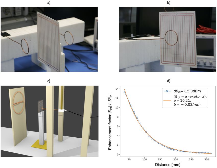
we show that a smart metasurface - a dynamic two-dimensional MTM - yields a significant SNR improvement for 3 T MRI
without affecting the transmit field. Electromagnetic MTMs, as outlined by the seminal works of Vesselago, Pendry, Schurig,
Leonhardt, and others15–19 are artificially constructed structures consisting of a usually periodic arrangement of dielectric
or conducting unit elements (small L-C circuits). Prominent application examples include MTM cloaks, perfect lenses, and
ultimately MRI applications20 . The unit cells can be considered as single meta-atoms on a sub-wavelength scale. Therefore, an
incident electromagnetic field is subject to a macroscopic influence induced by the interactions of all meta-atoms. Hence, w.r.t.
RF field interaction the MTM can be viewed as a homogeneous material slab, which is effectively described by (anisotropic and
dispersive) permeability and permittivity. In contrast to naturally occurring materials, MTMs can be designed to have arbitrary
positive and negative values for both parameters. This leads to, e.g., field enhancement or focusing, phase changes, and tailored
reflection and transmission properties. Usually, metasurfaces yield desired effects only for a specific target frequency with
a very narrow bandwidth. This property makes them ideal tools for MRI, which similarly builds on narrow bandwidth RF
radiation. It was shown previously that MTMs can be used to significantly improve the SNR without the need of stronger
background fields.21–28 However, passive structures as those presented in the available literature will of course influence both,
the transmit (Tx) as well as the receive (Rx) field. The influence during Tx corresponds to a local increase of power transmitted,
posing a potential threat of tissue heating and high SAR values. Moreover, obviously the Tx-field will be disturbed leading to a
range of unwanted effects and subtle consequences. Thus, it is utterly important to carefully design, test, and use MTMs in
MRI applications as patient safety must be assured at all times in research as well as clinical routine. To do so, dynamical
MTMs can be developed, which are (de-)tuned depending on the imaging phase, i.e., discrete or continuous resonance states
are to be introduced. This is indeed not trivial due to the MRI scanner’s strong magnetic field environment, which limits
electromagnetic signal communication close to the machine and causes some known control mechanisms for MTMs not to
work. So far, only very few tunable MRI MTMs have been presented in general, and there are even less proposals that achieve
the tuning depending on the imaging phase without the need of active intervention.29, 30 Non-linear MTMs29 are introduced as
a promising solution since they can be sensitive to the imaging phase but also MRI-compatible additional battery-powered
electronic sensing circuits30 can be used to take care of the state-switching. However, in all known cases the suggested MTMs
are bulky structures (such as helix-shaped configurations or 3d arrangements of conducting bars), putting patient-specific design,
patient comfort, and flexible or conformal manufacturing benefits beyond reach. The thickness of several centimeters also limits
possible imaging applications. To overcome these limitations, we developed smart and ultra-thin metasurface enhancement
plates (EPs) for MRI. Here, “smart” refers to automatic self-detuning in the Tx phase of the imaging. The functionality was
designed and tested via simulations and verified in on-bench experiments and MRI scans at 3 T. Depending on the imaging
sequence parameters, the SNR is increased up to eightfold (by a conservative measure) in slices close to the metasurface. A
generalization to different field strengths is easily possible, such that EPs can be constructed for, e.g., 1.5 T or 7 T scanners.
    Note that the MTMs (in general and those presented here in particular) do not act as MRI coils. Rather their effect is to
locally redistribute (focus) the Rx field (or Tx field in other applications) such that in combination with the scanner’s Tx and Rx
coils the SNR can be enhanced, leading to increased imaging efficiency. The smart metasurfaces here are designed to be used in
combination with the MRI scanner’s integrated body coil. Thus, they allow to build a kind of effective, local, universal (referred
to different imaging applications with the same metasurface), and wireless Rx coil, which is more cost-effective and simpler
w.r.t. dedicated Rx coils. MTMs which work in combination with other (local) Rx coils can also be designed but care needs to
be taken concerning the interaction of close resonant structures. However, as resonant, conducting structures are involved in the
construction, the design of MTMs for use in MRI applications may adopt and modify conventional Rx/Tx coil methodologies
and well-known geometries.

Results
Metasurface design paradigm and (de-)tuning mechanism
In the following, we present the final results of our iterative metamaterial design loop for smart metasurfaces. To avoid any
additional control circuitry components and batteries, we follow a design paradigm for non-linear MTMs29 , such that each of
our smart metasurface EPs consists of a non-linear system of two inductively coupled and resonant substructures. One of these
is a linear 2d MTM (linear metasurface) and the other one is a non-linear, single-loop tuning resonator; see Figs. 1d, 2a and
the supplementary material for a visual impression. In such an arrangement, resonant hybrid modes31 are determined by the
properties of each subsystem and the coupling mechanism. The fundamental mode is of primary interest for MRI applications
due to the largest region of interest (ROI) that can be covered. Our design has the advantage that instead of manipulating every
unit cell of the linear MTM separately, only the tuning resonator needs to be controlled to vary the resonance of the full EP.
Details on a theoretical description of such an arrangement via the coupled mode theory have been published before29 . In the
methods section, details on the design parameters for the EPs are outlined.
    Following the design methodology, each of our EPs is conceptually composed of i) a linear metasurface resonator consisting
of capacitively-loaded and coupled flat-wire unit cells, and ii) an outer single-loop tuning resonator, which is milled on the same

                                                                                                                             2/21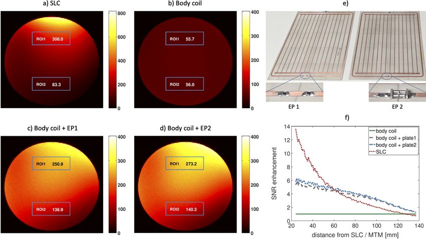
dielectric substrate and tightly covers the inner structure. The substrate is less than 0.6 mm thick with only 17 µm of copper
cladding, see the methods section for details. The tuning resonator is loaded with semi-conductor elements that are sensitive to
the incident power level via the induced current in the loop. In the Tx phase of the MRI sequence, substantially higher power is
incident as compared to the Rx phase, in which the signal is caused by the relaxation of the excited magnetization. Hence, the
resonance behavior of the tuning resonator is sensitive to the imaging phase and, thus, also the hybrid modes of the full EP
are influenced by the incident power. The result is a smart, non-linear metasurface of which the resonance properties change
between Tx and Rx without any additional need for user influence, control circuitry, batteries, or active (de-)tuning.
    The resonance at low incident power is made to coincide with the MRI scanner’s Larmor frequency (123.5 MHz here,
see the methods section) by the design of the metasurface such that the EP is active and resonant in the Rx phase while it is
sufficiently detuned (almost invisible) in Tx. For the first version (EP1), varactor diodes are soldered in series into the tuning
resonator, while in the second case (EP2) an MRI compatible limiter diode is used, see Fig. 3e. To provide the possibility of
manual fine-tuning of the resonance frequency at low incident power levels, a small trimmer capacitor was soldered into the
tuning resonator in either case. It allows to tune and characterize the smart metasurface on-bench in presence of a phantom
before using it in the MRI scanner. For the inner metasurface, the wire-resonator unit cells are loaded with capacitors, which
are implemented as simple rectangular patches on a ground plane (on the back layer, see the figures in the supplementary
material). In this way, the intensive use of lumped elements can be avoided to increase the Q-factor. In a next step, the
manufacturing on flexible substrates for patient-specific and/or conformal design for many different applications becomes
possible due to the compactness of the metasurfaces, the structural design that avoids lumped elements, and laser milling
on thin sub-millimeter substrates. This is a big advantage compared to existing (bulky) solutions that use helix-structures or
3d arrangements of wire-shaped conducting bars with a thickness of several centimeters in total. Note that our metasurface
resonator itself resembles properties of an open low-pass birdcage coil with the leg capacitors being a series of the two structural
parallel-plate ones at the wire ends. The metasurface design was successively iterated based on simulations and measurement
results, which are presented in the next sections.

Simulation and on-bench characterization results
For the B1 field enhancement in MRI, we are interested in the lowest-order resonant hybrid mode of the EP. Eigenmode
simulations were conducted to study the resonant modes of the substructures at first separately and then as a coupled system.
The lowest-order coupled modes involving the fundamental mode of the inner, linear metasurface are two: one in which the
fields generated by the substructures are in phase (mode of interest), whereas in the other one they are out of phase, see Fig. 1a.
In the next step, a plane wave excitation was used for full-wave simulations of the entire structure in presence of a cylindrical
phantom to assess the characteristics and to feedback the design loop.
    After successive design cycles, prototypes are manufactured for on-bench measurements of i) the resonance frequency as
a function of the incident power, and ii) the quality factor to assure the desired functionality. A typical setup composed of
shielded sniffer coils connected to a vector network analyzer was used, see Fig. 1d and the supplementary material. For S11
measurements at different incident power levels, the sniffer coil is positioned some distance above the center of the EP. The
self-detuning of the smart metasurface is clearly observable at increasing incident power, see Fig. 1e. The same setup is used to
fine-tune the EP at the target frequency at low incident power by variation of the trimmable capacitor. For the quality factor we
find Q = 110 for EP1 and Q = 103 for EP2. In Fig. 1f, the detuning of the EP as a function of the incident power is shown in
terms of S21 measurements with the sniffer coils positioned at a distance of 300 mm from each-other and the EP in the center.
This detuning can be observed as a shift towards lower frequencies of the maximum of S21 magnitude or as the drop of the
S21 magnitude at a fixed target frequency. In addition, a custom-made 3-axis scanning stage was used to further characterize
the spatial dependence of the S-parameter response of the metasurfaces as a function of incident power as shown in Figs. 1b
and c; see also the supplementary material for the setup. In the non-detuning regime (below about −15 dBm input power), we
observe an exponential decay of the field enhancement in the direction orthogonal to the EP. Depending on the input power,
enhancement factors of about 10 can be observed close to the surface in free space, see Fig. 1.

Magnetic resonance images and validation
MRI measurements prove the expected functionality of the smart metasurfaces. A gradient echo sequence is used with
the following parameters: T R = 100 ms, T E = 5 ms, field-of-view = {64 × 64, 128 × 128} mm2 , matrix size = 128 × 128,
bandwidth = 250 Hz/Px, eight slices with thickness of 5 mm and distance of 15 mm. The imaging is done with a homogeneous
cylindrical phantom (with both, EP1 and EP2) and with a Kiwi fruit for structural images (with EP1). For high SNR images of
the Kiwi, also measurements with increased T R = 1 s are performed. The scanner’s body coil is used for Tx throughout all
experiments and also for Rx in combination with the smart metasurfaces EP1 and EP2. For comparison, imaging is also done
with a local single loop coil (SLC) for Rx while the EP is removed. Besides the integrated body coil of the MRI scanner, the
SLC might be considered a standard to which a new MTM device should be compared in a first step.

                                                                                                                               3/21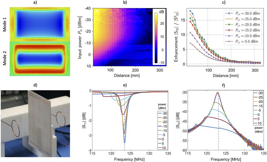
All measurements are performed with a single sequence implemented into the vendor-independent gammaSTAR framework
(Fraunhofer MEVIS)32, 33 with dedicated pauses between measurements to avoid frequency adjustments between successive
experiments with/without the metasurfaces, see also the methods section. To investigate the de-tuning behavior and to separate
effects on the Tx and Rx fields, 10 measurements with equidistant nominal flip angles between 0 and 90 degrees are recorded to
determine the Ernst angle, i.e., the flip angle leading to a maximal SNR. This approach allows to genuinely characterize MTMs
in MRI applications and to clearly differentiate between Tx and Rx modifications of the B1 field, see the methods section, but
this method is often missing in existing literature. Reference measurements are performed without any metasurface in either
case using only the body coil. The geometrical setup containing the phantom and the smart metasurface is shown in Fig. 2.
    The noise for all SNR evaluations is taken from the respective 0 deg flip angle measurement, which is a better and more
conservative measure than taking the noise from apparently “signal-free” areas in the actual images. The results in Fig. 3 and
Fig.4 prove that the detuning mechanism works perfectly well for both EPs. The Ernst angle is the same for measurements
with and without the smart metasurfaces, see Fig. 4d and the supplementary material. Hence, in the Tx phase of the imaging
sequence, the EPs remain silent and do not affect the B1 field. In the Rx phase, however, they lead to a sixfold increase in
SNR for homogeneous phantom measurements with T R = 100 ms and to an almost eightfold SNR increase for structural
measurements with T R = 1 s, see Figs. 3, 4, 5, and 6. The homogeneous phantom results in Fig. 3 show that both EPs work
approximately equally well. From Fig. 3f, one can see that after a certain penetration depth, roughly the diameter of the SLC,
the metasurfaces yield larger SNR improvements and outperform the local coil. Moreover, the profile for the SLC decreases
almost exponentially, whereas the enhancement factor due to the smart metasurfaces seems to decrease only linearly. This
behavior is confirmed in simulations and offers yet another advantage compared to existing solutions.

Discussion
Compared to the existing solutions for detunable MRI MTMs29, 30 , our smart metasurfaces exhibit a larger penetration depth
and slower decrease of the SNR enhancement factor while maintaining a similar or even better SNR enhancement performance.
The results clearly show that the SNR in MRI can be substantially improved with smart yet thin MTMs. Safety concerns are
taken care of by the automatic Tx detuning and the sub-millimeter structures set the foundation for the possibility of flexible and
conformal manufacturing. In some cases, the metasurfaces in combination with the scanner’s body coil even outperform a local
SLC. If the same image quality can be achieved without local coils, which are wired to the scanner’s interface, metasurfaces
have the potential to improve patient comfort and function effectively as universal “wireless receive coils”.

Methods
Simulation and metasurface design
All numerical electromagnetic simulations were performed using CST Microwave Studio (Dassault Systèmes, France) with
frequency domain solvers. Two different types of simulations, eigenmode analysis and full plane wave excitations, are employed.
The overall design requirement is to have the full smart metasurface resonant in the Rx phase of the imaging process at the
MRI scanner’s Larmor frequency, which is 123.5 MHz in our case (3 T Magnetom Skyra, Siemens Healthineers, Germany). To
achieve this goal, the wire-resonator metasurface can be varied in its overall dimension and the length of substructures as well as
the number of wire resonators can be adjusted. Changing the size of single wire resonators, the MTM unit cells, allows to shift
the resonance frequency. Furthermore, the variation of the end parts, the parallel plate capacitors, allows to vary the resonance
and coupling of the unit cells. Since the full structure gives rise to hybrid eigenmodes, also the coupling and the properties
of the outer, non-linear tuning resonator change the overall resonance frequency. Hence, parameter studies and optimization
were performed to find the best possible combination. For the two manufactured EPs, we use N = 14 wire-resonator unit cells,
which are 10 mm wide each, with printed wires of 1 mm width. The capacitive end patches have the same size for the two EPs,
9 × 3 mm2 , see Fig. 1 and the supplementary material. The length of an individual unit cell is 180 mm. Each EP consists of two
subsystems: the inner, linear metasurface and the outer, non-linear tuning resonator. These two subsystems were designed to
individually resonate at slightly higher frequencies, respectively, so that when inductively coupled together they would resonate
at the target frequency of the MRI system.
     For the simulations, semiconductor components (varactor diodes for EP1 and the limiter diode for EP2), are modeled as
fixed-value capacitors (lumped elements) with different discrete values for Tx and Rx, respectively. Full wave simulations
are performed with open boundary conditions in all directions and plane wave excitations with circular polarization. The
propagation direction of the plane wave is in the plane of the metasurface along the symmetry axis orthogonal to the wire
resonators. A homogeneous phantom of which the properties such as density, permittivity, and conductivity resemble average
values for tissue (εr = 78, σ = 0.7 S/m) was included to simulate the loading. Evaluations of the numerical results show that the
H-field at the target frequency inside the phantom is stronger in the resonant case (corresponding to the Rx phase of MRI) and
almost unaffected in the detuned case (corresponding to the Tx phase of the MRI sequence). Eigenmode simulations indicate

                                                                                                                             4/21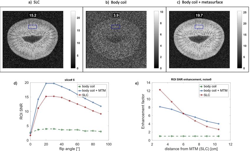
that two different hybrid modes exist that involve the fundamental mode of the linear metasurface, one of which has the two
subsystems in phase, see Fig. 1. For the other mode, the two are exactly out of phase but the homogeneity is improved in the
central part. For MRI, the first mode is of primary interest due to the larger region of interest covered.

Manufacturing, on-bench measurements and MRI scans
The metasurfaces are manufactured at the Fraunhofer Institute for High Frequency Physics and Radar Techniques (FHR) by
laser milling on Rogers 4003c substrate with a 17 µm copper layer on both sides. The tuning resonator loop used for automatic
detuning during the Tx phase is milled on the same layer as the capacitively-loaded wires. The substrate’s thickness is 0.508 mm.
For EP1, the varactor diode-loaded tuning loop has three readily available Skyworks SMV2020 varactor diodes in series to
have it resonate at a suitable frequency while keeping the geometrical dimensions adjusted to the inner substructure. The safe
use of these varactor diodes in a 3 T experiment was previously reported.29 However, varactor diodes connected in series give
rise to non-linear effects.34, 35 For EP2, the limiter diode-loaded loop is of the same size as the varactor-loaded loop of EP1 but
uses the UMX9989AP diode (Microsemi, USA). For low incident power, this limiter diode has a typical capacitance of about
4 pF. For high incident power, the limiter diode conducts and, thus, on/off states are realized as extreme cases depending on
the incident power level, i.e., depending on the MRI imaging phase. In the two extreme states, the resonance frequency of
the metasurface is different, with the low incident power state’s resonance frequency matched to the MRI scanner’s Larmor
frequency. On the back layer of the EPs, the ground stripes for the capacitively coupled wire resonators of the inner metasurface
are milled, see the supplementary material for an overview of front and back layers of the two manufactured prototypes.
     The characterization of the prototypes is performed on-bench with a symmetric coil setup and with a dedicated 3-axis
scanning stage, respectively, see Fig. 1 and the supplementary material. Fine-tuning is achieved via the trimmable capacitor in
the tuning resonator, which has a range of 2 pF to 6 pF. The on-bench measurements are performed with two untuned 60 mm
diameter sniffer coils and a vector network analyzer (N5242A, Keysight Technologies, USA), see Fig. 1 and the supplementary
material. The scattering S-parameters are measured as functions of the incident power to verify the desired de-tuning effect
for high field strengths. The Q-factor of the metasurfaces was determined from S21 measurements via the width at the 3 dB
decay from the maximum. For EP1 it is Q = 110, and for EP1 we have Q = 103. The spatial dependence of the S-parameter
distribution, as depicted in Fig. 1b and 1c, is determined with a workshop-built setup including a high-precision 3-axis scanning
stage (SF600, GAMPT, Germany), see the supplementary material. This setup consists of a low-bandpass, custom-build,
trimmable Tx coil with a diameter of 30 cm and a small Rx coil with a diameter of 2.5 cm, both of which are connected to
a 2-Port vector network analyzer (E5061B ENA Series Network Analyzer, Keysight Technologies, USA). In this setup, the
metasurface is mounted on a pylon of polystyrene at a distance of about 60 cm to the Tx coil. The effective scattering parameter
S21, as depicted in Fig. 1b, is measured on the central axis behind the metasurface and in planes parallel to the surface to
characterize the enhancement factor vs. distance and the field homogeneity, respectively. The effective values (magnitudes) are
obtained by subtracting (on a log scale) the background signal, i.e., the data from measurements without any metamaterial. The
deduced enhancement factor is on the order of magnitude of the enhancement seen in the MRI scans.
     For the MRI scans, the scanner’s body coil is used for Tx and also for Rx in combination with the smart metasurfaces,
respectively. For comparison, we also use a 70 mm SLC for Rx in absence of any EP. Such a local coil constitutes a Rx
standard to which MRI-compatible MTMs should be compared in a first step beyond the scanner’s body coil. However, such
a comparison is often missing in the existing literature. When the SLC is used, it is placed at the position of the removed
EP to allow for a fair comparison. All experiments are performed with a single sequence that offers sufficient time to place,
exchange, or remove the metasurfaces between successive acquisitions without allowing the scanner to do any new adjustments
in the meantime. In this way the genuine comparison and characterization is possible. We use gradient echo sequences
with the following parameters (if not stated otherwise in figure captions): T R = {100ms, 1s}, T E = 5 ms, field-of-view =
{64 × 64, 128 × 128} mm2 , matrix size = 128 × 128, bandwidth = 250 Hz/Px, eight slices with thickness of 5 mm and distance
of 15 mm. These sequences are implemented into the unique, vendor-independent gammaSTAR framework (Fraunhofer
MEVIS)32, 33 , which offers exceptional flexibility in sequence design and is optimally suited for MTM characterization as
shown here. It also allows, in principle, to repeat our analysis with MRI systems from different vendors. Reducing the scanner’s
internal image scaling factor is important. Even with the huge SNR enhancement factor, due to the presence of the smart
metasurface, artificial image saturation should be avoided. We performed measurements with a homogeneous cylindrical
phantom, see Figs. 2 and 3, and also with a Kiwi fruit for structural images, see Figs. 4 and 5. The supplementary material
contains additional MRI results.
     To prove that the smart detuning works in the Tx phase, imaging was performed for 10 different flip angles with equidistant
spacing, ranging from 0 deg to 90 deg. In the supplementary material we show additional results (to those in Figs. 4 and 5),
which relate the SNR enhancement in different ROIs for the homogenous and structural phantom measurements to the nominal
flip angle. As can be seen in all these plots, the presence of a smart metasurface does not affect the position of the maximal
SNR, i.e., the position of the flip angle that leads to a maximal SNR (Ernst angle). Hence, the SNR improvement due to the

                                                                                                                             5/21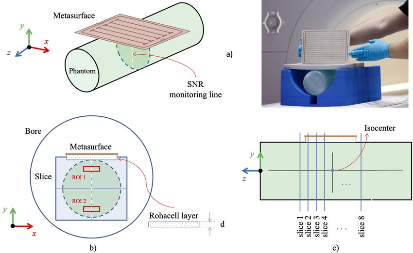
smart metasurface is related to effects on the Rx field only. If the Ernst angle for any MTM in MRI measurements was shifted
(as compared to body coil or SLC measurements), the MTM influences also the Tx field, which poses a potential threat to
the patient. Uncontrolled modifications of the Tx field by MTMs are to be avoided since also all scanner-integrated safety
mechanisms are not adapted to this situation.
    The definition of the noise obviously influences the SNR enhancement that the metasurfaces yield in comparison to the
body coil measurements. To characterize its effect, we evaluated the SNR performance for five different noise definitions /
regions. The most reliable and conceptually acceptable noise measure is to calculate the standard deviation of the ‘signal’ in a
large region of the 0 deg flip angle measurements. This also proves to be the most conservative measure in our consideration.
For comparison, we also calculated the noise as the standard deviation in the apparently signal-free areas in the edges of each
image. The results are presented in the supplementary material.
    For the structural images with the Kiwi fruit and T R = 1 s, the SNR enhancement factor due to the smart metasurface
is about eight in nearby slices, see Fig. 4 and the supplementary material. For the measurements with T R = 100 ms, the
enhancement factor is a bit less, see Figs. 4 and 5. However, especially in this case the influence of the metasurface is most
prominent as the fruit can barely be recognized in the plots without its presence but becomes clearly visible with internal
structure with a smart metasurface being used.
    As can be seen in Fig. 4, the SNR enhancement due to the metasurface tends to fall off almost linearly as compared
to the faster drop-off behavior of the SLC. This effect is also supported by simulation data, which shows that close to the
surface, the enhancement can be best fitted by a linear decay. However, the measurements with the 3-axis scanning stage
show an almost exponential decay of the enhancement vs. distance in the normal direction to the surface, see Fig. 1. This
difference can be explained by i) the absence of a phantom in the lab measurements and ii) the different normalization of the
enhancement. Whilst for the MRI scans, the enhancement is calculated w.r.t. the body coil SNR, which is almost constant for
the homogeneous phantom scans, the lab measurements yield the enhancement normalized to an empty scan, which itself has a
distance-dependent behavior related to the H-field of the Tx coil.

References
 1. Lauterbur, P. Image formation by induced local interactions - examples employing nuclear magnetic-resonance. Nature
    242, 190–191 (1973).
 2. Nishimura, D. G. Principles of magnetic resonance imaging / Dwight G. Nishimura. (D. Nishimura, S.l, 2010), ed. 1.1.
    edn.
 3. Cao, Z., Park, J., Cho, Z.-H. & Collins, C. M. Numerical evaluation of image homogeneity, signal-to-noise ratio, and
    specific absorption rate for human brain imaging at 1.5, 3, 7, 10.5, and 14t in an 8-channel transmit/receive array. J. Magn.
    Reson. Imaging 41, 1432–1439, DOI: https://doi.org/10.1002/jmri.24689 (2015). https://onlinelibrary.wiley.com/doi/pdf/
    10.1002/jmri.24689.
 4. Ocali, O. & Atalar, E. Ultimate intrinsic signal-to-noise ratio in mri. Magn. Reson. Medicine 39, 462–473, DOI:
    https://doi.org/10.1002/mrm.1910390317 (1998). https://onlinelibrary.wiley.com/doi/pdf/10.1002/mrm.1910390317.
 5. Schick, F. Whole-body mri at high field: technical limits and clinical potential. Eur. Radiol. 15, 946–959 (2005).
 6. Caserta, J., Beck, B. & Fitzsimmons, J. Reduction of wave phenomena in high-field mri experiments using absorbing
    layers. J. magnetic resonance 169 2, 187–95 (2004).
 7. Zhang, X. et al. In vivo blood t1 measurements at 1.5 t, 3 t, and 7 t. Magn. Reson. Medicine 70 (2013).
 8. Ham, C. L., Engels, J. M., van de Wiel, G. T. & Machielsen, A. Peripheral nerve stimulation during mri: Effects of high
    gradient amplitudes and switching rates. J. Magn. Reson. Imaging 7 (1997).
 9. Reilly, J. Maximum pulsed electromagnetic field limits based on peripheral nerve stimulation: application to ieee/ansi
    c95.1 electromagnetic field standards. IEEE Transactions on Biomed. Eng. 45, 137–141 (1998).
10. Uecker, M. et al. Real-time mri at a resolution of 20 ms. NMR Biomed. 23 (2010).
11. Griswold, M. et al. Generalized autocalibrating partially parallel acquisitions (grappa). Magn. Reson. Medicine 47 (2002).
12. Pruessmann, K., Weiger, M., Scheidegger, M. & Boesiger, P. Sense: Sensitivity encoding for fast mri. Magn. Reson.
    Medicine 42 (1999).
13. Lustig, M., Donoho, D. & Pauly, J. Sparse mri: The application of compressed sensing for rapid mr imaging. Magn. Reson.
    Medicine 58 (2007).
14. Corea, J. et al. Screen-printed flexible mri receive coils. Nat. Commun. 7 (2016).

                                                                                                                            6/21
15. Veselago, V. The electrodynamics of substances with simultaneously negative values of epsilon and mu. Physics-Uspekhi
10, 509–514 (1968).
16. Pendry, J., Schurig, D. & Smith, D. Controlling electromagnetic fields. Science 312, 1780 – 1782 (2006).
17. Schurig, D. et al. Metamaterial electromagnetic cloak at microwave frequencies. Science 314, 977 – 980 (2006).
18. Leonhardt, U. Optical conformal mapping. Science 312, 1777 – 1780 (2006).
19. Leonhardt, U. & Philbin, T. General relativity in electrical engineering. New J. Phys. 8, 247–247 (2006).
20. Solymar, L. & Shamonina, E. Waves in Metamaterials (OUP Oxford, 2009).
21. Schmidt, R., Slobozhanyuk, A., Belov, P. & Webb, A. Flexible and compact hybrid metasurfaces for enhanced ultra high
field in vivo magnetic resonance imaging. Sci. Reports 7 (2017).
22. Duan, G., Zhao, X., Anderson, S. & Zhang, X. Boosting magnetic resonance imaging signal-to-noise ratio using magnetic
metamaterials. Commun. Phys. 2, 1–8 (2019).
23. Freire, M., Jelínek, L., Marqués, R. & Lapine, M. On the applications of mu=-1 metamaterial lenses for magnetic resonance
imaging. J. magnetic resonance 203 1, 81–90 (2010).
24. Kretov, E., Shchelokova, A. & Slobozhanyuk, A. Impact of wire metasurface eigenmode on the sensitivity enhancement of
mri system. Appl. Phys. Lett. 112, 033501 (2018).
25. Kretov, E., Shchelokova, A. & Slobozhanyuk, A. Control of the magnetic near-field pattern inside mri machine with
tunable metasurface. Appl. Phys. Lett. 115, 061604 (2019).
26. Shchelokova, A. et al. Experimental investigation of a metasurface resonator for in vivo imaging at 1.5t. J. magnetic
resonance 286, 78–81 (2018).
27. Shchelokova, A. V. et al. Locally enhanced image quality with tunable hybrid metasurfaces. Phys. Rev. Appl. 9, 014020,
DOI: 10.1103/PhysRevApplied.9.014020 (2018).
28. Slobozhanyuk, A. et al. Enhancement of magnetic resonance imaging with metasurfaces. Adv. materials 28 9, 1832–8
(2016).
29. Zhao, X., Duan, G., Wu, K., Anderson, S. & Zhang, X. Intelligent metamaterials based on nonlinearity for magnetic
resonance imaging. Adv. materials e1905461 (2019).
30. Saha, S. C. et al. A smart switching system to enable automatic tuning and detuning of metamaterial resonators in mri
scans. Sci. Reports 10 (2020).
31. Jouvaud, C., Abdeddaim, R., Larrat, B. & Rosny, J. D. Volume coil based on hybridized resonators for magnetic resonance
imaging. Appl. Phys. Lett. 108, 023503 (2016).
32. Cordes, C., Konstandin, S., Porter, D. & Günther, M. Portable and platform-independent mr pulse sequence programs.
Magn. Reson. Medicine 83, 1277 – 1290 (2019).
33. MEVIS, F. gammastar (2020).
34. Powell, D., Shadrivov, I., Kivshar, Y. & Gorkunov, M. Self-tuning mechanisms of nonlinear split-ring resonators. Appl.
Phys. Lett. 91, 144107 (2007).
35. Wang, B., Zhou, J., Koschny, T. & Soukoulis, C. Nonlinear properties of split-ring resonators. Opt. express 16, 16058–63
(2008).
Acknowledgements
This work was supported by the Fraunhofer MAVO project MetaRF. The authors want to thank Peter Erhard for discussions
and comments and Michael Jäger for support in the production of prototypes.
Author contributions statement
E.S. was responsible for the design and simulation of the metasurface EPs and performed on-bench characterizations. T.B., R.U.
and J.J. suggested components and advised the design process. D.B. assisted with simulations and on-bench measurements. S.K.
and M.G. drafted and performed the MRI measurements. S.K. developed and implemented the sequence into the gammaSTAR
framework and evaluated measurement data. R.N.W. performed on-bench S-parameter measurements and developed the 3-axis
S-parameter measurement setup. D.P. assisted with simulations and metasurface design, evaluated the MRI measurements,
drafted the paper, and produced the figures. M.G. and T.B. initialized the research project. All authors were involved in the
discussion and interpretation of the results presented and all contributed to writing the final paper.
7/21Additional information
Supporting Information including extended figures and measurement data is available online and from the corresponding author.
The authors declare no conflict of interest.
The experimental research with plants (kiwi fruit used for MRI scans) complies with relevant institutional, national, and
international guidelines and legislation. The fruit was obtained from a local grocery store.
8/21Figure 1. On-bench- characterization of the metasurfaces. a) Simulation of the first two hybrid eigenmodes (normalized
H-field component orthogonal to the metasurface). b) Measurement of the effective S21 parameter (magnitude) on the central
axis as a function of distance and input power at 123.5 MHz with a 3-axis scanning stage; see the supplementary material. c)
Enhancement factor curves for selected input power levels from b). d) Symmetric on-bench setup with untuned sniffer coils
that leads to the scattering parameters S11 and S21 shown in e) and f) as a function of incident excitation power.
9/21Figure 2. Orientation of the metasurface in MRI scans. a) 3D view of the setup, the photo shows the arrangement in the MRI
scanning room on the patient table. b) Setup as seen from an axial plane. The SNR monitoring line and the two regions of
interest are indicated. Between the metasurface and the phantom, a Rohacell layer of thickness d = 1.5 cm is used. c) Sagittal
view of the orientation and recorded slices. The phantom was positioned in the isocenter. Note that for structural images with
the Kiwi fruit, the slices are parallel to the enhancement plate.
10/21Figure 3. MRI results for homogeneous phantom scans. The SNR in slice# 4 is shown for a flip angle of 70 deg (approx.
Ernst angle) with Rx by a) the SLC, b) the body coil, c) body coil + EP1, and d) body coil + EP2. The SNR in the two ROIs is
indicated, respectively. e) Photo of the two EPs. The insets show the elements that are responsible for detuning in Tx. f) The
normalized SNR enhancement (w.r.t. the body coil) in slice# 4 on a central vertical line, see Fig. 2. At a certain distance, the
EPs outperform the SLC. Either EP leads to a sixfold increase in SNR close to the surface, which falls off almost linearly in
contrast to the SLC’s exponential behavior.
11/21Figure 4. MRI results for structural images with EP1 using a kiwi fruit and T R = 100 ms. The SNR is shown for slice# 5 and
Rx by a) the SLC, b) the body coil, and c) body coil + smart metasurface (EP1). Note that the slices are parallel to the
metasurface. The SNR in the ROI is indicated, respectively. d) SNR in the ROI as a function of the flip angle in slice# 5. The
Ernst angle is not shifted in presence of the metasurface. Hence, the SNR increase is only due to influence on the Rx field. e)
The SNR as a function of distance from the SLC / EP for the measurement with T R = 1 s and flip angle of 75 deg (approx.
Ernst angle). At a certain distance, the metasurface outperforms the SLC. Compared to the body coil, the metasurface leads to
an eightfold increase in the SNR close to the surface.
12/21Slice #2 Slice #3 Slice #4
Slice #5 Slice #6 Slice #7
Figure 5. Additional MRI results for structural images with the Kiwi fruit and T R = 100 ms. The plots show the comparison
of results for the body coil (top) and the body coil + smart metasurface (bottom) in each panel. The flip angle is the approx.
Ernst angle in this configuration. The respective SNR in the ROI is indicated in the subfigures.
13/21Slice #2 Slice #3 Slice #4
Slice #5 Slice #6 Slice #7
Figure 6. Additional MRI results for structural images with the Kiwi fruit and T R = 1 s. The plots show the comparison of
results for the body coil (top) and the body coil + smart metasurface (bottom) in each panel. The flip angle is the approx. Ernst
angle in this configuration. The respective SNR in the ROI is indicated in the subfigures.
14/21Supplementary Material
Additional Figures and Data
This file contains supplementary material in the form of extended figures and measurement data.
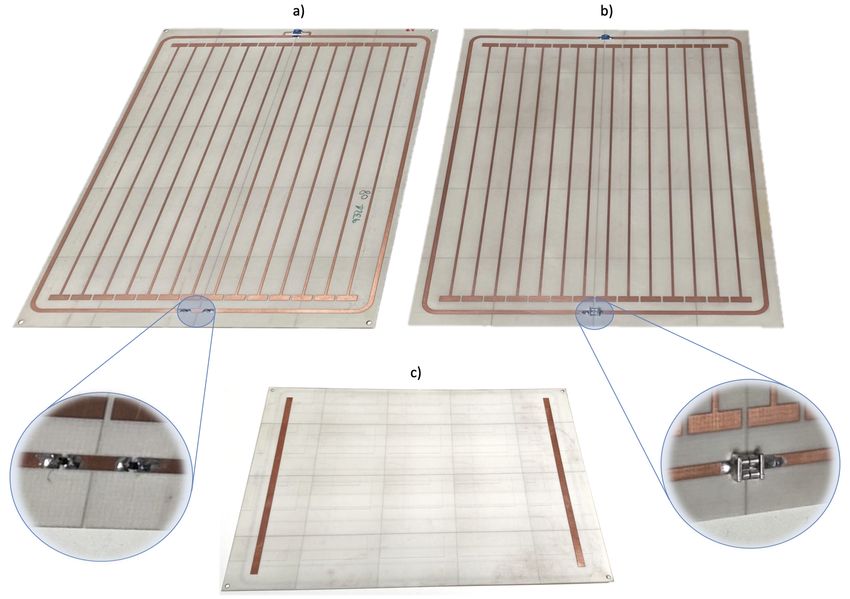
15/21S 1. The two manufactured smart metasurface enhancement plates with a) varactor-loaded tuning resonator and b)
limiter-diode-loaded tuning resonator. c) The back of the plate with the ground patches for capacitively coupled wire resonator
unit cells is shown, which is the same for both EPs. The ground stripes on the back in combination with the rectangular patches
at the end of the wire-resonators on the front form parallel plate capacitors and couple the individual unit cells.
16/21S 2. On-bench characterization of the manufactured prototypes using un-tuned sniffer coils and a vector network analyzer. a)
Two sniffer coils positioned for S21 measurements. b) A single sniffer coil closer to the EP for S11 measurements. c)
Schematic of the setup used for measurements of the spatial dependence of scattering parameters. d) Fit of the exponential
decay of the enhancement factor as a function of the distance. At −15 dBm input power, we observe an exponential decay of
about 0.02/mm.
17/21S 3. Additional MRI results for structural images with the Kiwi fruit with T R = 100 ms. The plots show the SNR in the ROI in
different slices (see Fig. 4). The slices are parallel to the metasurface, i.e., the slice number is a measure of distance. The
maximum’s position is unchanged by the presence of the metasurface in all slices, respectively. This indicates that the EP only
influences the Rx field.
18/21a) b)
Noise2 Noise4
ROI
Noise3 Noise1
c) d)
e) f)
S 4. Additional MRI results for structural images with the Kiwi fruit with T R = 1 s. The plots show the normalized (w.r.t. the
body coil) SNR in the ROI vs. distance from the metasurface for different noise definitions. For noise0, the noise is calculated
from the 0 deg flip angle measurements, see the methods section. In all other cases, the noise is the standard deviation in the
indicated apparently ‘signal-free’ areas, respectively. The smart metasurface enhancement factor drops off slower with
increasing distance as compared to the SLC. As can be seen, it depends, of course, on the definition of “noise” but the noise as
calculated from the 0 deg flip angle scans gives the most conservative measure.
19/21S 5. Additional MRI data for phantom measurements. The SNR is shown in the two ROIs as a function of the flip angle for
slices# 1–4. The maximum’s position (Ernst angle) is unchanged in presence of either EP, thus, the smart metasurfaces do not
influence the Tx field and the SNR increase is purely due to Rx effects.
20/21S 6. Extension of the previous figure for slices# 5–8.
21/21You can also read