3 G MOBILE (UMTS) 1.1 UMTS AND THE INFORMATION SOCIETY
←
→
Page content transcription
If your browser does not render page correctly, please read the page content below
3 G MOBILE (UMTS)
1.1 UMTS AND THE INFORMATION SOCIETY
Rapid advancements in Information and Communications Technology (ICT) have already
had a profound impact on life in the 21st century. The growth of knowledge-based societies
present great opportunities and challenges for the social and economic health of all countries.
New telecommunications technologies such as UMTS will play a central role in the smooth
transition to an Information Society by providing people with fast, unlimited access to
information and services at anytime, from anywhere.

1.2 INTRODUCTION TO UMTS
  •    UMTS is the convergence of mobile communications, Information Technology (IT)
      and multimedia technologies. UMTS creates new opportunities for network operators,
      service providers and content providers to generate revenue and seize market share. The
      benefit of UMTS is richer, more powerful communication. UMTS is a suite of radio
      and network technologies that provide:
   • better spectrum efficiency,
   • high data transmission rates (up to 2 Mbit/s),
   • worldwide roaming capability,
   • the capability to offer new multimedia applications and services,
   • interoperability with both fixed and mobile telecommunications services.
UMTS is the natural evolution from GSM and other second generation (2G)mobile systems.
It provides interconnection with 2G networks as well as other terrestrial nd satellite-based
networks. UMTS presents a unique opportunity to cater to the needs of individuals in the
Information Society. As a multi-national, multi-sector system that supports numerous
protocols and transport technologies, UMTS eliminates barriers that oneposed problems for
communications and enables the creation and delivery of fully personalized communication
services to both mass market and corporate users.

1.3 UMTS STANDARD/
UMTS is an International Mobile Telecommunications - 2000 (IMT-2000) 3G system. he 3rd
eneration Partnership Project is developing technical specifications or IMT-2000 and the
International Telecommunication Union (ITU) framework for hird-generation standards.
3GPP is a global co-operation between six organizational artners including European
Telecommunications Standards Institute (ETSI), ho are recognized as being the world’s
major standardization bodies. ee figure 1 for an illustration of the 3G standardization
environment. The other main IMT–2000 system proposed by the ITU is CDMA 2000.
Operators ith existing IS-95 networks will migrate to CDMA 2000. CDMA 2000 will be
eployed in North America and Asia. DMA 2000 is a narrowband system whereas UMTS,
which uses WCDMA technology, s a wideband system. The first available release of CDMA
2000 does ot provide transmission speeds recommended by the IMT-2000. However, the irst
UMTS release (3GPP Release 99) is on time and guarantees recommended peeds. CDMA
2000 will eventually deliver full IMT-2000 requirements. SM systems dominate the global
market share of 2G systems. Western Europe, or example, exclusively uses the GSM
standard. The UMTS standard will likely capture the majority of the 3G market share.

                                                                                          1
Figure 1 : 3G standardization environment
1.4 UMTS SATISFIES MARKET DEMANDS
Significant market potential exists for UMTS. Recent trends indicate a rising demand
For Internet Protocol (IP) services which include access to:
• the Internet,
• intranets and extranets,
• mobility,
• multimedia services,
• speed (fast data transmission rates).
1.5 OVERVIEW OF UMTS RELEASE ARCHITECTURES
This section provides a general description of the current standard UMTS release
architectures. UMTS architectures provide a smooth transition from second generation
telecommunications systems by slowly phasing in new software and new network elements.
3GPP currently defines standards for the following UMTS releases
• 3GPP Release 99 (R99),
• 3GPP Release 4 (Next Generation Network (NGN) architecture),
• 3GPP Release 5 (all-IP core network).
Note : Release 2000 (R00) is split into “Release 4” and “Release 5”. See table 3 for a
summary of the 3GPP standard release architectures.
2Table 3 : Summary of 3GPP network architectures
1.5.1 3GPP RELEASE 99 (R99)
3GPP Release 99 (R99) includes the following network elements:
• Radio Access Networks:
Base Station Subsystem (BSS) for access to GSM services which includes:
• Base Transceiver Stations (BTS),
• Base Station Controller (BSC).
Universal Terrestrial Radio Access Network (UTRAN) for access to UMTS services and
including:
• Node Bs,
• Radio Network Controller (RNC).
Core Network:
Circuit-Switched Core Network (CSCN) includes elements that support circuit switched
connections. Circuit-switched connections are connections where the operator has full and
exclusive use of the circuit until the connection is released. CSCN elements for R99 include:
• Mobile services Switching Center (MSC),
The MSC is the interface between the Radio Access Network (RAN) and fixed networks. It
provides mobility management, call control and switching functions to enable circuit-
switched services to and from mobile stations.
• Gateway Mobile services Switching Center (GMSC),
The GMSC interfaces with the fixed networks, handles subscriber location information from
the HLR and performs routing functions to and from mobile stations. GMSC functionality
can be contained in all or some of the MSCs of the network, depending on network
configuration.
• InterWorking Function (IWF),
3The IWF provides interworking functionality between a Public Land Mobile Network
(PLMN) and fixed networks (such as ISDN, PSTN and PDN). The IWF converts protocols
used in the PLMN to those used in the corresponding fixed network.
• Packet-Switched Core Network (PSCN)
includes elements that support packet switching technology. Packet-switching technology
routes packets of user data independently of one another. No dedicated circuit is established.
Each packet can be sent along different circuits depending on the network resources
available. PSCN elements for R99 include:
• Serving GPRS Support Node (SGSN),
The SGSN and the GGSN are the interface elements between the RAN and fixed networks.
The SGSN provides mobilitiy management, session management and transfer and routing
functions to enable the transfer of packet-switched data services.
• Gateway GPRS Support Node (GGSN),
The GGSN handles subscriber location information and provides packet data transfer
capabilities to and from mobile terminals.
• Border Gateway (BG),
The BG provides connectivity, and interworking and roaming capabilities between two
different PLMNs. Common Core Network elements are elements used by both the CSCN and
PSCN. Common elements for R99 include:
• Home Location Register (HLR),
The HLR is the permanent database for mobile subscriber information. The HLR is in charge
of mobile subscriber management.
• Visitor Location Register (VLR),
The VLR manages mobile subscribers in the home PLMN and those roaming in a foreign
PLMN. The VLR exchanges information with the HLR.
• Authentication Center (AuC),
The AuC provides authentication and encryption functions for system security
• Equipment Identity Register (EIR),
The EIR stores information on mobile equipment identities.
• SMS MSCs.
SMS MSCs enable the transfer of messages between the Short Message Service Center and
the PLMN.
See figure 11 for an illustration of 3GPP Release 99 network architecture.
4Figure 11 : 3GPP Release 99 architecture
1.5.2 3GPP RELEASE 4 (R4)
3GPP Release 4 implements the NGN architecture in the core network, separating the control
and user planes. This enables a true separation of control and connection operations, and
provides the independence of applications and services from basic switching and transport
technologies. 3GPP Release 4 (R4) introduces the following new network elements in
addition to R99 elements:
Core Network:
CSCN:
• MSC server,
The MSC server provides call control and mobility management functions for an MSC. It
also holds subscriber service data information and provides connection control for media
channels in a CS-MGW.
• GMSC server,
The GMSC server provides call control and mobility management functions for a GMSC.
• Circuit-Switched-Media GateWay (CS-MGW).
The CS-MGW is an interface between the UTRAN and the Core Network. The CS-MGW
supports both UMTS and GSM media. CS-MGW terminates bearer channels from circuit-
switched networks and media streams from packet networks. It supports media conversion,
5bearer control and payload processing. See figure 12 for an illustration of 3GPP Release 4
network architecture.
Figure 12 : 3GPP Release 4 architecture
1.5.3 3GPP RELEASE 5 (R5)
3GPP Release 5 implements a unified IP backbone infrastructure which enables high
performance services and functions. 3GPP Release 5 (R5) introduces the following new
network elements in addition to R99 and R4 elements:
Core Network:
Common Core Network elements:
• Home Subscriber Server (HSS),
• Internet protocol Multimedia (IM) subsystem.
The IM susbsystem consists of all Core Network elements that use the services provided by
the PSCN to offer multimedia services. The IM susbsystem primarily includes the Call Server
• Control Function (CSCF), Media Gateway
Control Function (MGCF) and the Multimedia Resource Function (MRF).
See figure 13 for an illustration of 3GPP Release 5.
6Figure 13 : 3GPP Release 5 architecture
1.6 UMTS TECHNOLOGY
The main technological difference between 2G and 3G systems is the new multiple access
technique in the Radio Access Network (RAN) that increases bandwidth and efficiency. This
technology is called Code Division Multiple Access (CDMA). 3G standards organizations
have selected three CDMA radio interface technologies for 3G networks:
• WCDMA which uses Frequency Duplex Division (FDD) mode,
• TD-CDMA which uses Time Division Duplex (TDD) mode,
• CDMA 2000 which is seen as the natural evolution for operators with existing IS-95
networks.
This section describes:
• the limitations of 2G systems,
• WCDMA,
7• Asynchronous Transfer Mode (ATM),
• UMTS - Satellite mode (S-UMTS).
1.6.1 LIMITATIONS OF 2G SYSTEMS
The limitations of 2G mobile systems such as GSM include:
• congestion,
There are more than 300 million wireless subscribers worldwide and thus a need to increase
system capacity.
• limited mobility around the world,
• There is a need for global standardization.
• limited services.
• There is a need for new multimedia applications and services.
1.6.2 Wideband - Code Division Multiple Access (WCDMA)
WCDMA optimally divides the available radio spectrum on the air interface into a number of
channels and defines how these channels are allocated to the many users accessing the
network. WCDMA allows for variable bit rates and variable Quality of Service (QoS).
WCDMA provides:
• better spectrum efficiency,
• wider coverage,
• support for all types of services (circuit, packet and multimedia),
• enhanced privacy,
To illustrate how WCDMA works, take the example of the “cocktail party”. Picture a
room filled with many people, all speaking in a different language to a “super
translator” in the middle of the room. See figure 14 for an illustration of the “cocktail
party”:
Fig
ure 14 : “Cocktail party”
The room represents the area covered by one cell in a UMTS PLMN.
Each person represents a UE in the cell.
Each language corresponds to a code.
Each conversation represents a signal.
The “super translator” represents the Node B.
81.6.1.1 Spread Spectrum modulation
Each person sees the other conversations with the “super translator” as noise. As
more people enter the room, the room gets noisier. The translator hears more noise
and so do the people. The noise or interference level quickly increases to the extent
that it interferes with the conversations.
WCDMA is a noise-limited technology. The capacity of the system, or the number of
simultaneous users is limited by the level of noise in the cell. A digital coding technique
called Spread Spectrum limits the level of noise in the cell and provides secure voice and data
transmission over the radio interface. Spread Spectrum takes a signal in the form of packet
data and spreads it over a wider range of bandwidth than the actual content of information in
the signal requires. The transmitted signal is multiplied by a code which increases the number
of bits transmitted and expands the bandwidth used. The signal’s power is spread over a
larger band of frequencies which makes the signal appear as random noise to a casual
listener. In this way, Spread Spectrum is highly secure because the signal is less susceptible
to outside interference. Intruders must have knowledge of the code in order to recuperate the
signal. Receivers recognize a spread signal and multiply it by the same code to retrieve
its original form.
1.6.1.2 Power Control
As more and more people show up for the “cocktail party”, the partygoers must move
closer to the translator in order to be heard, or must speak more loudly. Unhappily,
the people at the edge of the room are no longer heard by the translator in the
middle so they start to speak more loudly. Consequently, the noise level in the room
continues to increase. The translator solves the problem by requesting that each
person speak loud enough to be heard, but no louder.
A WCDMA system requires accurate power control to overcome the “near-far” problem. A
signal close to the base station (Node B) with high power overwhelms the other signals from
mobile phones that are farther away. The goal of power control in WCDMA is to have the
signals from all of the User Equipments (UE) arrive at the base station with the same power
level. If the transmitter is close to the receiver, less power is necessary. If the transmitter is
farther away, more power is necessary. WCDMA systems use two types of power control:
• Open-loop power control:
Open-loop power control is based on the sum of the power level of the UE and the power
level of the Node B. The two power levels must remain a constant. In other words, if the UE
receives a strong downlink signal from the Node B, then the UE will speak low. If the UE
receives a weak signal downlink signal then the UE will speak loudly.
• Closed-loop power control:
With closed-loop power control, power control bits are sent to the UE every 0.66
milliseconds to tell the mobile station to increase or decrease its transmission power. Closed-
loop power control is very fast. Because of Power Control, WCDMA phones have fewer
power requirements which means they can handle smaller, lightweight, longer-life batteries.
Rake receiver In UMTS, a Rake receiver is implemented in the UEs and base stations to
provide:
• multi-service,
• path diversity,
• soft handover.
A Rake receiver can decode several signals simultaneously and combine them to improve the
quality of the signal or to get several services at the same time. In radio communications, the
9strength of a signal can decrease for many reasons. Natural obstacles such as buildings and
hills cause reflections, diffractions and scattering. Consequently, multipath propagation
occurs which means that the same radio signal arrives at the receiver through different
reflected paths. The Rake receiver uses the inherent frequency diversity characteristics of
WCDMA as a means of providing redundancy in the network. Because the signal is spread
over a wide frequency band, it is transmitted and received simultaneously on two or more
frequencies. The Rake receiver identifies the different paths that the signal takes and
combines them to improve the quality of the signal.
• Soft Handover
Soft Handover means that the connection does not have to be broken in the original cell
before connection in the successor cell. Soft Handover is possible with UMTS because
WCDMA systems do not require the use of different frequencies in adjacent cells. Two
mobile terminals use the same frequency band. A mobile terminal needs only one
transmission chain to decode both simultaneously.
See figure 15 for an illustration of UMTS cell division.
Figure 15 : UMTS cell division
1.6.2 ASYNCHRONOUS TRANSFER MODE (ATM)
UMTS uses ATM in the Radio Access Network (RAN) for the reliable transfer of digital
information. ATM has been chosen as the transport technology in UMTS Radio Access
Networks because it supports a multi-service environment with variable bit rates and the
ability to support variable QoS. ATM is also highly scalable which makes it excellent for
interconnecting legacy systems and LANs and for building WANs on high-performance
fiber-optic networks.
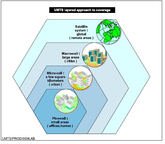
1.6.3 SATELLITE UMTS (S-UMTS)
Satellite UMTS (S-UMTS) uses a single frequency band for communications betweenterrestrial and
satellite networks. Satellite technology can readily provide global coverage and will play an
10important role for UMTS in the future. The specifications for S-UMTS are ongoing. See
figure 16 for an illustration of UMTS coverage.
Figure 16 : UMTS coverage AQ
11You can also read