SRT Avant Fleet User's Manual - Scandinavian Radio ...
←
→
Page content transcription
If your browser does not render page correctly, please read the page content below
SRT Avant Fleet User’s Manual
Scandinavian Radio Technology AB

Table of Contents
Introduction to SRT Avant Fleet .............................................................................................................. 4
   Scope ................................................................................................................................................... 4
   General Characteristics ....................................................................................................................... 4
       General ............................................................................................................................................ 4
       Electrical .......................................................................................................................................... 4
       Physical ............................................................................................................................................ 4
       Interfaces ......................................................................................................................................... 4
Safety Precautions ................................................................................................................................... 5
   RF Exposure ......................................................................................................................................... 5
       General Statement on RF Energy .................................................................................................... 5
   Distraction ........................................................................................................................................... 5
       Driving ............................................................................................................................................. 5
   Product Handling ................................................................................................................................. 5
       General Statement on Handling and Use ........................................................................................ 5
       Electrostatic Discharge (ESD)........................................................................................................... 6
       Air Bags ............................................................................................................................................ 6
       Seizures/ Blackouts.......................................................................................................................... 6
       Emergency Calls............................................................................................................................... 6
       Loud Noise ....................................................................................................................................... 6
   Electrical Safety ................................................................................................................................... 6
       Accessories ...................................................................................................................................... 6
       Faulty and Damaged Products......................................................................................................... 6
   Interference ......................................................................................................................................... 6
       General Statement on Interference ................................................................................................ 6
       Hearing aids ..................................................................................................................................... 6
       Medical Devices ............................................................................................................................... 7
       Hospitals .......................................................................................................................................... 7
       Aircraft ............................................................................................................................................. 7
       Interference in Cars ......................................................................................................................... 7
   Explosive Environments ...................................................................................................................... 7
       Petrol Stations and Explosive Atmospheres .................................................................................... 7
       Blasting Caps and Areas................................................................................................................... 7
Declaration of RoHS Compliance............................................................................................................. 8
WEEE Notice ............................................................................................................................................ 9
EC DECLARATION OF CONFORMITY ...................................................................................................... 10
Hardware Interfaces .............................................................................................................................. 11
   SIM interface ..................................................................................................................................... 11
   I/O interface ...................................................................................................................................... 11
       Control A & Control C .................................................................................................................... 11
       Control B ........................................................................................................................................ 12
       Power............................................................................................................................................. 12
       VBATT ............................................................................................................................................ 13
       AIN1/AIN2...................................................................................................................................... 13
       RLIN/RLOUT ................................................................................................................................... 13

SRT Avant Fleet User’s Manual v1.2.0                                                                                                                         2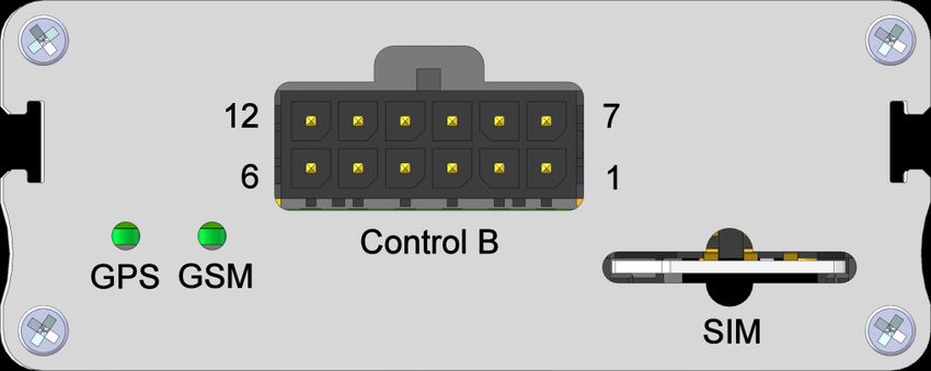
Scandinavian Radio Technology AB

     AUXAlarm and PBAlarm ................................................................................................................ 13
     VSAlarm ......................................................................................................................................... 13
     IRAlarm .......................................................................................................................................... 13
     Privacy ........................................................................................................................................... 13
     IGN and AUXCTRL .......................................................................................................................... 14
     TSAlarm ......................................................................................................................................... 14
     On/Off............................................................................................................................................ 14
     Mic+/Mic- ...................................................................................................................................... 14
     Spk+/Spk- ....................................................................................................................................... 14
     GSM Status .................................................................................................................................... 14
  RF interface ....................................................................................................................................... 15
     GSM RF connection ....................................................................................................................... 15
     GSM RF performance .................................................................................................................... 15
     GPS RF connection......................................................................................................................... 15
  Indicators ........................................................................................................................................... 15
     GSM Status .................................................................................................................................... 15
     GPS Status...................................................................................................................................... 15

SRT Avant Fleet User’s Manual v1.2.0                                                                                                                     3
Scandinavian Radio Technology AB Introduction to SRT Avant Fleet Scope This document describes the hardware SRT Avant Fleet. SRT Avant Fleet is based on a quad-band WISMO™ Q2687 module and includes a SiRF Star III based GPS solution. General Characteristics General Quad Band GSM modem E-GSM 850/900/1800/1900 GPRS Class 10 Class 4 (2W at 850/900 MHz) Class 1 (1W at 1800/1900 MHz) SMS and GPRS communication Internal 1.8V/3V SIM interface Fully type approved according to GSM Phase 2+ specifications 12-36V DC power supply or single-cell Li-Ion battery operation with built-in charger circuitry 20-channel GPS receiver Electrical Power supply 12-36V DC, 5VA peak during transmission peaks Maximum 2A peak power consumption during transmission pulses in GSM 900 at 2W Physical 90x59x23.5mm external dimensions Weight: 200g Operating temperature: -20°C to +55°C Storage temperature: -35°C to +85°C Interfaces SMA type antenna connector, 50Ω, for GSM MCX type antenna connector, 50Ω, for GPS SIM card holder with 1.8V/3V SIM interface 16-pin (2x8) Microfit connector (Control A) 12-pin (2x6) Microfit connector (Control B) 8-pin (1x8) Microfit connector (Control C) SRT Avant Fleet User’s Manual v1.2.0 4
Scandinavian Radio Technology AB
Safety Precautions
RF Exposure
General Statement on RF Energy
SRT Avant Fleet contains a transmitter and a receiver. When it is ON, it receives and transmits RF
energy. When you communicate with SRT Avant Fleet, the system handling your communication
controls the power level at which your personal protection device transmits.
Distraction
Driving
Full attention must be given to driving at all times in order to reduce the risk of an accident. Using
your unit while driving causes distraction and can lead to an accident. You must comply with local
laws and regulations restricting the use of wireless devices while driving.
Product Handling
General Statement on Handling and Use
You alone are responsible for how you use your device and any consequences of its use. You must
always switch off your device wherever the use of a wireless device is prohibited. Use of your device
is subject to safety measures designed to protect users and their environment.
Always treat your device and its accessories with care and keep it in a clean and dust-free
place.
Do not expose your device or its accessories to open flames or lit tobacco products.
Do not expose your device or its accessories to liquid, moisture or high humidity.
Do not drop, throw or try to bend your device or its accessories.
Do not use harsh chemicals, cleaning solvents, or aerosols to clean the device or its
accessories.
Do not paint your device or its accessories.
Do not attempt to disassemble your device or its accessories, only authorized personnel
must do so.
Do not expose your device or its accessories to extreme temperatures.
Please check local regulations for disposal of electronic products.
SRT Avant Fleet User’s Manual v1.2.0 5Scandinavian Radio Technology AB Electrostatic Discharge (ESD) Do not touch the SIM card’s and Microfit connectors’ metallic parts. Air Bags Do not place the unit in the area over an air bag or in the air bag deployment area. Store the unit safely before driving your vehicle. Seizures/ Blackouts The unit can produce a bright or a flashing light. Emergency Calls This equipment, like any wireless equipment, operates using radio signals, which cannot guarantee connection in all conditions. Therefore, you must never rely solely on any wireless equipment for emergency communications. Loud Noise This extension unit is capable of producing loud noises which may damage your hearing. Electrical Safety Accessories Use only approved accessories. Do not connect with incompatible products or accessories. Faulty and Damaged Products Do not attempt to disassemble the equipment or its accessory. Only qualified personnel must service or repair the equipment or its accessory. If your equipment or its accessory has been submerged in water, punctured, or subjected to a severe fall, do not use it until you have taken it to be checked at an authorized service center. Interference General Statement on Interference Care must be taken when using the device in close proximity to personal medical devices, such as pacemakers and hearing aids. Hearing aids People with hearing aids or other cochlear implants may experience interfering noises when using wireless devices or when one is nearby. The level of interference will depend on the type of hearing device and the distance from the interference source, increasing the separation between them may reduce the interference. You may also consult your hearing aid manufacturer to discuss alternatives. SRT Avant Fleet User’s Manual v1.2.0 6
Scandinavian Radio Technology AB

Medical Devices
Please consult your doctor and the device manufacturer to determine if operation of your equipment
may interfere with the operation of your medical device.

Hospitals
Switch off your wireless device when requested to do so in hospitals, clinics or health care facilities.
These requests are designed to prevent possible interference with sensitive medical equipment.

Aircraft
Switch off your wireless device whenever you are instructed to do so by airport or airline staff.

Interference in Cars
Please note that because of possible interference to electronic equipment, some vehicle
manufactures forbid the use of wireless devices in their vehicles.

Explosive Environments
Petrol Stations and Explosive Atmospheres
In locations with potentially explosive atmospheres, obey all posted signs to turn off wireless devices
such as SRT Avant Fleet or other radio equipment.
Areas with potentially explosive atmospheres include fuelling areas, below decks on boats, fuel or
chemical transfer or storage facilities, areas where the air contains chemicals or particles, such as
grain, dust or metal powders.

Blasting Caps and Areas
Turn off your wireless device when in a blasting area or in areas posted turn off “two-way radios” or
“electronic devices” to avoid interfering with blasting operations.

SRT Avant Fleet User’s Manual v1.2.0                                                                       7
Scandinavian Radio Technology AB

Declaration of RoHS Compliance
To minimize the environmental impact and take more responsibility to the earth we live in, this
document shall serve as formal declaration that the SRT Avant Fleet manufactured by
SCANDINAVIAN RADIO TECHNOLOGY AB is in compliance with the Directive 2002/95/EC of the
European Parliament – RoHS (Restriction of Hazardous Substances) with respect to the following
substances:

       (1) Lead (Pb)
       (2) Mercury (Hg)
       (3) Cadmium (Cd)
       (4) Hexavalent Chromium (Cr (VI))
       (5) Polybrominated biphenyls (PBB’s)
       (6) Polybrominated diphenyl ethers (PBDE’s)
       (Compliance is evidenced by written declaration from our suppliers, assuring that any
       potential trace contamination levels of the substances listed above are below the maximum
       level set by EU 2002/95/EC, or are exempt due to their application.)

The SRT Avant Fleet manufactured by SCANDINAVIAN RADIO TECHNOLOGY AB, meets the
requirements of EU 2002/95/EC.

SRT Avant Fleet User’s Manual v1.2.0                                                               8
Scandinavian Radio Technology AB
WEEE Notice
The Directive on Waste Electrical and Electronic Equipment (WEEE), which entered into force as
European law on 13th February 2003, resulted in a major change in the treatment of electrical
equipment at end-of-life. The purpose of this Directive is, as a first priority, the prevention of WEEE,
and in addition, to promote the reuse, recycling and other forms of recovery of such wastes so as to
reduce disposal.
1. When this crossed-out wheeled bin symbol (WEEE logo) is attached to a product it means the
product is covered by the European Directive 2002/96/CE.
2. All electrical and electronic products should be disposed of separately from the municipal
waste stream via appointed by the government or the local authorities.
3. The correct disposal of your old appliance will help prevent negative consequences for the
environment and human health.
For more information about electronic and electrical waste equipment disposal, recovery,
and collection points, please contact your local city center, household waste disposal service,
shop from where you purchased the equipment, or manufacturer of the equipment.
SRT Avant Fleet User’s Manual v1.2.0 9Scandinavian Radio Technology AB
EC DECLARATION OF CONFORMITY
The undersigned, representing the following manufacturer
Name: Scandinavian Radio Technology AB
Address: Box 23 162 11 Vällingby, Sweden
Telephone: +46 8 620 2960
Telefax: +46 8 620 2979
herewith declares that the product
Type of equipment: GSM/GPRS/GPS device
Brand name/trade mark: SRT 278 Avant Fleet
Model/type: SRT 278 Avant Fleet
Batch/serial number: 35211900000000 to 35211900999999
complies with the essential requirements of Article 3 of the R&TTE 1999/5/EC
directive. The following standards have been applied:
Reference no Title
EN 60 950-1:2005 R&TTE Directive related to safety
EN 60 950-1/A11:2009
EN 301 489-1 V1.8.1 R&TTE Directive related to electromagnetic
EN 301 489-7 V1.3.1 compatibility
EN 301 511 R&TTE Directive related to efficient use of radio
frequency spectrum
Vällingby 2010-02-12
Tahir Albayrak
Managing Director of Scandinavian Radio Technology AB
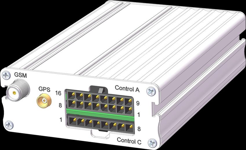
SRT Avant Fleet User’s Manual v1.2.0 10Scandinavian Radio Technology AB Hardware Interfaces SIM interface A 1.8V/3V SIM Card Reader is integrated in SRT Avant Fleet. The SIM interface signals are protected by transient voltage suppression diodes to prevent any Electro Static Discharge. The interface is fully compliant with GSM 11.11 recommendations concerning SIM functions. I/O interface The SRT Avant Fleet is equipped with three I/O connectors. The I/O signals are managed through the firmware commands. Control A & Control C Control A is a 16-pin Microfit connector with two rows of eight pins each. Control C is an 8-pin Microfit connector with one row of eight pins. Figure 1 - Control A & C Table 1 - Control A pinout Pin # Name Description 1 VIN+ 12-36V DC input 2 VIN- Power ground 3 AUXAlarm Auxiliary alarm input 4 AIN1 Analog input 1 5 VBATT 3.3-4.2V DC output 6 AIN2 Analog input 2 7 Bat+ External battery positive pole 8 RLIN Relay input 9 Ignition Ignition input 10 PBAlarm Pushbutton alarm input 11 AUXCTRL Auxiliary control input 12 PRV Privacy input 13 GND Signal ground 14 VSAlarm Vibration sensor input 15 Bat-/GND External battery negative pole/Signal ground 16 RLOUT Relay output SRT Avant Fleet User’s Manual v1.2.0 11
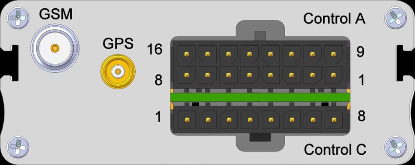
Scandinavian Radio Technology AB

Table 2 - Control C pinout
Pin #       Name               Description
1           Mic+               Microphone input positive pole
2           Mic-               Microphone input negative pole
3           Spk+               Speaker output positive pole
4           Spk-               Speaker output negative pole
5           GSM Status         GSM Status output
6           GND                Signal ground
7           On/Off             On/Off input
8           VBATT              3.3-4.2V DC output

Control B
Control B is a 12-pin Microfit connector with two rows of six pins each.
Figure 2 - Control B pinout

Table 3 - Control B
Pin #       Name               Description
1           VBATT              3.3-4.2V DC output
2           DBGMode            Reserved
3           On/Off             On/Off input
4           GND                Signal ground
5           CT104              Reserved
6           CT106              Reserved
7           Mode               Reserved
8           IRAlarm            IR detector input
9           VBATT              3.3-4.2V DC output
10          TSAlarm            Temperature sensor input
11          CT103              Reserved
12          CT105              Reserved

Power
SRT Avant Fleet may be powered by a 12-36V DC power supply, an internal single-cell Li-Ion battery
or an external battery.
If an external power source of 12-36 VDC is available, this must be connected to VIN+ and VIN-
inputs.
If the unit is delivered with an internal battery, the external battery connector can’t be used.
Otherwise the external battery, which has to be equipped with a protection circuitry, must be
connected to Bat+ and Bat- inputs.
When an external power source is available, charging of the battery, whether it is external or
internal, is controlled by the software. The maximum charge current is 500 mA.

SRT Avant Fleet User’s Manual v1.2.0                                                             12
Scandinavian Radio Technology AB

VBATT
The internal working voltage VBATT may vary between 3.3 and 4.2V DC depending on the power
supply alternative used and the current battery status.
If an external power supply is used to power the unit, VBATT is fixed at 4.0V.
If the unit is running on battery power (no power supply connected or otherwise not used due to low
power), VBATT follows the battery voltage, which should normally be between 3.3V and 4.2V DC.

AIN1/AIN2
These inputs can be used either as general purpose analog inputs or as analog alarm inputs. The
permitted analog input signal level is 0-5V DC.

RLIN/RLOUT
RLIN and RLOUT are connected to input respective output of a relay inside the unit. The relay is
controlled by software.
On SRT Avant Fleet X08, the relay is a MOSFET device and care is needed to connect external
equipment correctly because there is no electrical isolation between the signal connected to relay
and the equipment. On SRT Avant Fleet X09, the relay is an electromechanical device with electrical
isolation. In both cases the relay is dimensioned for a current of 1A at 12-36 VDC.

AUXAlarm and PBAlarm
These inputs can be used either as general purpose digital inputs or as digital alarm inputs.
They can be configured either as normally closed inputs or as normally open inputs when used for
alarm purposes.
For closed condition, the input must be connected to GND. For open condition the input must be left
floating.

VSAlarm
Depending on the hardware configuration the product comes with at delivery upon customer
request, this input can be used in two different ways.
The first option is that VSAlarm input operates precisely in the same way as AUXAlarm and PBAlarm
inputs.
The second option is that this input is not available for external connection and used for an internal
vibration sensor circuit type MS24M manufactured by Assemtech.

IRAlarm
This input signal is intended to be used with an infrared motion detector sensor circuit type Napion
AMN1 with digital output manufactured by Panasonic. Such a sensor requires three connections:
digital output, power supply and ground. If your application requires such an IR sensor, connect the
digital output of the sensor to this input. The power supply and ground leads of the sensor should be
connected to VBATT and GND respectively.

Privacy
This input is a general purpose digital input. Under software control it can be used to enable/disable
privacy mode to prevent that SRT Avant Fleet transmits GPS information if privacy mode is enabled.
This input is a normally closed input, i.e. it is off when it is connected to ground and on when it is
floating.

SRT Avant Fleet User’s Manual v1.2.0                                                                 13
Scandinavian Radio Technology AB

IGN and AUXCTRL
The IGN input can be used as a general purpose digital input or as an digital input of which the on
time can be measured or as a tool to control the GSM/GPS operation of SRT Avant Fleet.
The AUXCTRL input can be used as a general purpose digital input or as a digital input of which the on
time can be measured.
They are active high inputs, i.e. they are off when they are floating and on when they are connected
to a signal of 12-36V DC.

TSAlarm
This input signal is intended to be used with a temperature sensor circuit type DS18B20
manufactured by Maxim.
Such a sensor requires three connections: IO, power supply and ground.
If your application requires such a temperature sensor, connect the IO lead of a DS18B20 to this
input. The power supply and ground leads of the sensor should be connected to VBATT and GND
respectively.

On/Off
This input signal is intended to be used to turn the unit on or off without cutting the power supply. If
this signal is left open, the unit is off. To turn the unit on, this signal must be connected to VBATT.

Mic+/Mic-
The Mic+ and Mic- inputs are differential microphone inputs. They already include the convenient
biasing for an electret microphone so that such a microphone can be directly connected on those
inputs.

Spk+/Spk-
The Spk+ and Spk-outputs are differential speaker outputs. They can drive a load resistance of down
to 8 ohm.

GSM Status
This signal is identical to the signal which is used to drive the internal GSM status LED. If the
customer needs to have an external LED to display the GSM status, this signal may be used. For help
about how to connect an external LED to this input, the customer needs to contact Scandinavian
Radio Technology AB.

SRT Avant Fleet User’s Manual v1.2.0                                                                  14
Scandinavian Radio Technology AB

RF interface
GSM RF connection
The integrated GSM antenna connector of the SRT Avant Fleet is a SMA connector.
The SMA connector incorporates a "screw-on" latching action in order to make the connection
secure with an excellent RF performance. The characteristic impedance of SMA coaxial connector is
50Ω.
The antenna must fulfill the following requirements:
                         GSM 850         E-GSM 900        DCS 1800            PCS 1900
Frequency RX             869-894MHz 925-960MHz 1805-1880MHz 1930-1990MHz
Frequency TX             824-849MHz 880-915MHz 1710-1785MHz 1850-1910MHz
Impedance                50Ω
VSWR
You can also read