Beam Shaping and Power Handling of an Spatial Light Modulator system for Laser Induced Periodic Surface Structuring Tex-turation - Laser4surf
←
→
Page content transcription
If your browser does not render page correctly, please read the page content below
Proceedings of LPM2020 – the 21st International Symposium on Laser Precision Microfabrication

Beam Shaping and Power Handling of an Spatial Light Modula-
tor system for Laser Induced Periodic Surface Structuring Tex-
                           turation

                               Julien Dupuy*, Hendrik Von Horsten, Marc Lamblin and Yves Hernandez

                                         Multitel a.s.b.l, Parc Initialis, Mons, BE 7000
                                      *
                                       Corresponding author’s e-mail: dupuy@multitel.be

                Laser Induced Periodic Surface Structuring (LIPSS) is a powerful tool for creating sub-
            micrometric features on large surfaces in an up-scalable and industrial way. In order to control the
            process and reach a sufficient uniformity for some applications a careful attention must be paid to
            the control of the laser beam parameters like its polarization, stability and shape. A uniform beam
            shape is mandatory in some cases. Although some demonstrations of beam shaping with high power
            handling optical components have been made, there is not much reported regarding the use of SLM
            (Spatial Light Modulator) for beam shaping of ultrashort pulses. In the current work we show the
            possibility to use SLM with different type of laser sources, including a femtosecond system deliver-
            ing up to 1 mJ per pulses.

            Keywords: SLM, LIPSS, beam shaping.

1. Introduction                                                           In this work we present the use of a commercial SLM
    Various micro-machining processes based on lasers re-             beam shaping system with femtosecond pulses for the gen-
quire a total control of the beam shape for accurate and              eration of LIPSS. We will discuss the initial performances
regular patterning. The Gaussian beam shape exhibited by              of the component and its optimization with adequate ther-
the laser source must be, most of the time, converted into a          mal management [8] and then the application of the device
homogeneous top-hat shape. Such shape permits a uniform               for LIPSS generation on stainless steel.
distribution of light onto the sample. This is particularly the
case for Laser Induced Periodic Surface Structuring                   2. Initial performance of the SLM device
(LIPSS) process [1]. The ripples generated by LIPSS and in                We used a spatial light modulator from the company
particular their periodicity, strongly depend on the laser            HoloEye. The PLUTO-2 device is a reflective LCOS PAN
fluence.                                                              (Parallel Aligned Nematic)-SLM and allows for phase
   LIPSS had found lot of scientific and industrial applica-          modulation. It has an array of 1920 x 1080 pixels. The Pix-
tions, such as antireflection [2], colorization [3], hydropho-        el pitch of the modulator is 8 µm. The device frame rate is
bic surface [4] and biological devices [5], so the im-                60 Hz and, to address the pixels, a HDTV 8 bits grayscale
portance of fabrication and modulation of LIPSS on large              image must be uploaded via a HDMI display port. The fill
surface area is a popular topic.                                      factor of the modulator is 93%.
    The orientation of the LIPSS patterns depends on the                  Our first observations with this module were the fol-
laser beam polarization [6]. Then, the orientation of the             lowing:
polarization can be also required for reaching given func-                - The output beam shaping result is strongly depend-
tionalities and even polarization modification during the             ant on the quality of the input beam. One needs to maxim-
process can be desired for some specific applications. Po-            ize the pixels surface illumination with a good fitting input
larization control can be achieved easily for linear polariza-        beam
tion orientation, with classical, high optical damage thresh-             - The device operation showed power limitations: the
old optics, but one should just pay attention to the used of          SLM worked properly up to 7W in nanosecond pulsed re-
multiple elements together: SLM and polarization control              gime (100ns, 1mJ pulses).
for instance.                                                             - The device output power is sensitive to input polari-
    Beam shaping can be achieved with classical diffractive           zation state: Due to the polarization properties of the ne-
optical elements in order for instance to get a uniform top-          matic liquid-crystal SLM, an input laser beam linearly po-
hat shape [7]. This is a robust and cost-effective solution           larized needs to have the good angle to maximize the re-
that suffers only one drawback which is its non-                      flection of the SLM. The use of a half wave plate in front
reconfigurable mode of operation. Regarding this aspect,              of the device to align the polarization is required.
spatial light modulators provide much more flexibility but
are more limited in terms of power and energy handling.

                                                                  1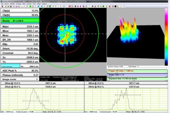
Proceedings of LPM2020 – the 21st International Symposium on Laser Precision Microfabrication
Fig. 3 Evolution of the SLM temperature in function of the ns laser
Fig. 1 Monitoring of the optical power variation at the input average power with and without water cooling.
output of the SLM in function of the polarization
input angle. In CW mode the device was tested with more than
100W at 1064nm, but for pulsed applications, with high
Depending of the polarization angle of the laser input peak powers, one needs to be careful especially if the beam
beam, the measured power losses of the SLM system vary diameter is very small and average power density is quite
from 7 to 65%. high > 50W/cm². Based on this water-cooling holder we
were able to demonstrate power handling larger than 20 W
3. SLM improvements on power handling average power in nanosecond regime and up to 1 mJ with
We designed a specific holder for the SLM device. This 500 fs pulses (2 GW peak power) without observed degra-
holder permits a water cooling of the SLM plate. The SLM dation.
is mounted directly against a copper chamber with water
circulation (Fig.2 (1)). A small frame (Fig.2 (2)) fix the 4. Implementation of the SLM on a laser microm-
SLM panel. An Aluminium base (Fig.2 (3)) was made to achining bench
hold the copper chamber and fix mechanically the device
on a breadboard for experiments.
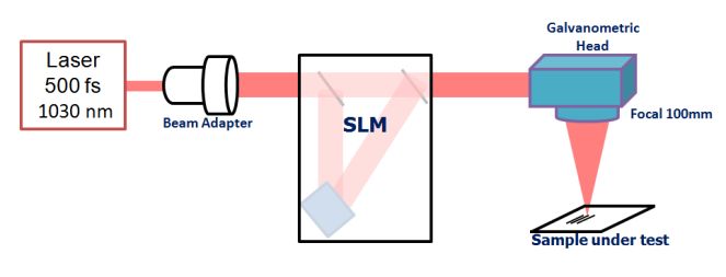
Fig. 4 Laser Setup for testing the SLM module.
Fig. 2 CAD of the SLM water cooling holder. The SLM module was inserted on a laser micromachin-
ing setup. A Beam Expender is mandatory in order to adapt
The base and the copper chamber contain also embed- the initial Gaussian beam diameter to the maximum surface
ded thermistors to monitor the temperature. of the LCOS-PAN panel. We worked here with a 8mm
Based on this holder, we were able to carry new power beam diameter (2ω0) at the entrance.
handling tests, with three different IR lasers: a continuous We placed two flip mirrors on the beam path in order to
wave (CW) laser operating @1064nm, a nanosecond fiber easily switch between the pristine Gaussian beam of the
laser which can deliver 20W 1mJ 200ns pulses, and an USP femtosecond laser, and the beam after shaping by the SLM,
(Ultra-short Pulses) laser @1030nm which can deliver for a better comparison of the micromachining results.
4 Watts average power with mJ pulses. In front of the SLM device, we used a half-wave plate,
held in a rotation mount, to control the incident polarization
of the laser beam on the SLM panel and maximise its re-
flectance (Fig1). Before the output mirror (second flip mir-
ror) we placed another half-wave plate in a rotation mount
as well to change the output polarization for LIPSS process
control.
After the SLM, we have a 4f configuration consisting of
two plano-convex fused silica lenses, with an AR-coating
and 100 mm focal length, with a diaphragm (which acts
like a high-pass filter on the optical FFT generated by the
SLM).
2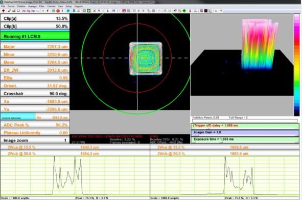
Proceedings of LPM2020 – the 21st International Symposium on Laser Precision Microfabrication

                                                                           energy density required to produce LIPSS and only abla-
                                                                           tion appeared.
                                                                               Then we fixed the repetition rate of the laser at 100kHz
                                                                           in order to have sufficient energy per pulse and also for
                                                                           easy testing with low scanning speeds (below 500 mm/s).

    Fig. 5 Beam shaping after the SLM, pictures taken just after the            Fig. 7 Laser impacts on a Silicon Wafer V250mm/s 100kHz
             SLM and 4F filter. Laser source used : 1030nm 500fs                    (Left) Gaussian Beam   (Right) SLM beam shaped
                                100kHz 40µJ.

    We controlled the beam shape and size with a Dataray
beam-profiling camera. We used the software provided by
the SLM manufacturer Holoeye to generate patterns. It has
already an embedded function to convert Gaussian to
square top-hat beam. Depending on the phase map algo-
rithm or the picture sent to the computing unit of the SLM,
we produced a square shape but the energy distribution
inside was unperfect (no flat top). We could make some
improvements with a dynamic corrective feedback loop
that precisely analyzes the shape, diameter and defects of
the Gaussian beam at the input of SLM (wavefront correc-
tion) [9]

                                                                              Fig. 8 Laser scribed lines on a Silicon Wafer V50mm/s 100kHz
                                                                                    (Left) Gaussian Beam, (Right) SLM beam shaped

                                                                               The focused laser spot size is smaller with a Gaussian
                                                                           beam than the square top hat shape (~30µm vs 55µm, esti-
                                                                           mated and measured on the sample).
                                                                           For all the tests performed, with unitary laser shots or with
                                                                           scribed lines, we can clearly see a better energy distribution
                                                                           on the material using the SLM module with a square top
                                                                           hat shape, compared with the initial Gaussian laser beam of
                                                                           the laser.
        Fig. 6 Beam shaping with SLM : shape after a focal lens
              f100mm; picture taken after the galvanometric head at        5.2 LIPSS texturation tests with the SLM Module
                         +50 mm after the focal point.                         We worked mainly with inox316L polished sheets of
                                                                           0.25mm thickness. The LIPSS was produced with a laser
  The figure 6 gives us an evaluation of the shape and en-
                                                                           beam emitting at 1030nm and delivering 500fs pulses at a
ergy distribution at the vicinity of the focal point. We
                                                                           repetition rate of 100 kHz and an average power of 3.3W.
placed the Dataray camera directly onto the beam. This
                                                                               This parameter gives us a single shot fluence near
method made it impossible to capture the exact focal point
                                                                           1J/cm².The scanning speed was 250mm/s, corresponding to
because of the energy density and the camera resolution.
                                                                           an approximate number of pulses of 22 and a cumulative
                                                                           fluence of 24J/cm². These values are comparable with simi-
5. Tests
                                                                           lar experiments from the literature [10] on stainless steel.
5.1 Non-overlapping laser shots and scanning lines
with the SLM module
    First, we tested a unitary laser shot on the materials. For
this experiment, the laser frequency was fixed at 1kHz and
the maximum energy per pulse was near 1mJ. This experi-
ence produced pulses with high and uniform energy depos-
ited on the sample, but we were also far higher than the

                                                                       3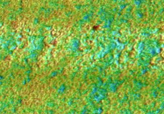
Proceedings of LPM2020 – the 21st International Symposium on Laser Precision Microfabrication
[4] B. Wu, M. Zhoua, J. Li, X. Ye, G. Li, and L. Cai: Appl.
Surf. Sci., 256, (2009) 61.
[5] T.S. Drakakis: App. Phy. Lett., 89, (2006) 144108.
[6] U. Hermens, M. Pothen, K. Win, K. Arntz, and F.
Klocke: Opt. Lasers Engin., 101, (2018) 44.
[7] G. Zhu, D. Whitehead, W. Perrie, O.J. Allegre, V. Olle,
Q. Li, Y. Tang, K. Dawson, Y. Jin, S.P. Edwardson, L.
Li, and G. Dearden: J. Phys. D: Appl. Phys., 51 (2018)
095603.
[8] R. J Beck, J. P Parry, W. N MacPherson, A. Waddie,
N. J Weston, J. D Shephard, and D. P Hand: Opt. Ex-
press, 18, (2018) 17059.
[9] S. Li, Z. Lu, P. Du, Y. Wang, L. Ding, and X. Yan:
Proc. SPIE, Vol. 10710, (2018) 107103Q.
[10] T. Jwad, P. Penchev, V. Nasrollahi, and S. Dimov:
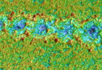
Fig. 9 LIPSS performed on INOX 316L with the SLM Module
coupled with the 500fs laser. App. Surf. Sci., 453, (2018) 449.
[11] L. Wang, Q. Chen, X. Cao, R. Buividas, X. Wang, S.
On figure 9, we can clearly see homogenous LIPSS Juodkazis, and H. Sun: Light Sci. Appl., 6, (2017)
with a well-defined border between the initial surface and 17112.
the irradiated one. We have obtained a period of 930nm [12] J. Huang, L. Jiang, X. Li, A. Wong, Z. Wang, Q.
with peak to valley height 945nm Δ120nm on all the 48µm Wang, J. Hu, L. Qu, T. Cui, and Y. Lu: Nanophotonics,
scribed laser line width. 8, (2019) 869.
6. Conclusion
We tested the possibility of using a thermalized Spatial
Light Modulator for beam shaping with three different la-
sers:
- a nanosecond laser, up to 20W and 1 mJ,
- a CW laser up to 100 W
- a femtosecond laser delivering up to 1mJ (2 GW
peak power).
We still don't know the laser power handling limit un-
der femtosecond regime for the water cooled SLM as we
were limited by the available average power and energy
from our laser sources.
The global system permits both polarization and beam
shape control for producing homogeneous LIPSS patterns
in a dynamically reconfigurable way. Mainly used to shape
the laser in a square flat top-hat shape, the SLM also per-
mits a flexible and adaptive laser beam shaping. Although
other methods can provide homogenous LIPSS with a well-
defined border, even fabricated by Gaussian beam [11 12],
The use of this SLM device to produce regular ripples pat-
terns is more ready to be integrated on industrial microm-
achining machine with high power USP laser.
This system was applied to stainless steel texturing. Regu-
lar LIPSS could be generated at a scanning speed of 250
mm/s.
Acknowledgments
This work was carried out within the frame of the project
LASER4SURF, funding from the European Union's Hori-
zon 2020 research and innovation program under grant
agreement No 768636.
References
[1] G.R.B.E. Römer, A.J. Huis in’t Veld, J. Meijer, and
M.N.W. Groenendijkb: CIRP Annals, 58, (2009) 201.
[2] A.Y. Vorobyev and C. Guo: Opt. Express, 19, (2011)
1031.
[3] A.Y. Vorobyev and C. Guo: Appl. Phys. Lett., 92,
(2008) 041914.
4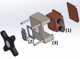

You can also read