ATR Chassis For Conduction-Cooled VME Boards
←
→
Page content transcription
If your browser does not render page correctly, please read the page content below
Product Information

ATR Chassis
For Conduction-Cooled VME Boards

     Available in multiple ARINC 404A
     sizes: 1ATRLong, 1ATRShort,
     3/4ATRShort, 1/2ATRShort
    Choice of cooling options:
    – Fan assisted with integral fan
    – Using air ducted through a rear plenum
    – Conduction through base or sidewall
    – Liquid
     Pluggable 28 VDC, 115 VAC and
     270VDC power supplies
     Supplied as a low risk wired,
     integrated and tested subsystem or as
     an un-configured chassis
     Supported by a full obsolescence
     management service

Radstone ATR chassis provide the highest level of environmental protection
combined with exceptional packing density and thermal performance.
Boards are clamped in place using expanding screw driven wedgelock
assemblies and cooling is entirely by conduction through internal chassis
walls. No cooling air passes over the boards themselves and as a result they
are completely protected from airborne contaminants. Heat is extracted
from the chassis by air or liquid being passed through sidewall heat
exchangers or by conduction to a suitable cold-plate.

Radstone’s level 4 and 5 conduction-cooled boards meet IEEE 1101.2-
1992. The ATRs will accept boards from any vendor meeting this
international standard.

All Radstone chassis products are backed up by a range of integration
services. During the early design phase these include thermal modelling,
mechanical adaptation and electronic interface design. Then, as the
program moves on, software engineering is on hand to support
development, provide system level Built-In-Test (BIT) and where necessary
integrate third party boards and peripherals. Finally dedicated teams of
engineers provide ILS data, qualification support, obsolescence
management and through life support. A one-stop shop for an out-of-the-
box and ready-to-run solution.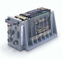
General Construction
                                                                                      All Radstone ATR chassis provide
   1ATRS-FIV
                                                                                      unparalleled strength and protection
   Construction
                                                                                      for fragile internal electronics. The
                                                                                      chassis meet the ARINC 404 profile
                                                                                      with hold downs to ARINC 600,
                                                                                      positioned to ARINC 404 in order to
                                                                                      maximize front panel connector area.

                                                                                      Feed-through filters and a “dirty box”
                                                                                      arrangement contain primary power
                                                                                      transients and prevent transmission to
                                                                                      internal electronics or the “461”
                                                                                      compliant PSU.

                                                                                      If required the chassis can also
                                                                                      be supplied with
                                                                                      hermetic sealing

                                                                                  1ATRS with rear
                                                                                  air plenum
                                                                                  (1ATRS-IV)

The Design Process                                                    Tracked Backplanes
Radstone has privileged access to board level design data             A “tracked” backplane integrates the majority of I/O
and this combined with a library of proven system                     signals in order to produce a single Line Replaceable Unit.
components, makes Radstone a cost effective choice when               Design time will depend upon complexity but as the cost
it comes to ATR configuration and board level integration.            of a “tracked” backplane approximates to that of a bare,
                                                                      unconfigured, standard backplane, then each configured
Following architecture definition, the ATR design process             system will benefit from a reduced labor overhead.
normally begins with a thermal analysis. This will provide
optimum board level slot positions and confirm that card              Video and high speed digital traces are not normally
edge temperatures remain within design limits. Mechanical             integrated during this process and will normally be routed
design will then follow. This will include front panel                directly from the rear of the backplane to front panel
connector cut-outs but it may also include provision for              connectors by means of discrete wires.
peripherals and any other specific chassis adaptation.                Front Panel Flexi-Connections
For portability, the chassis wiring schedule will take the form       For significant production runs it is often cost effective to
of a Microsoft Excel spreadsheet and even though this may             design specific flexi-circuits to link the “tracked” system
suggest particular front panel connector positions, specific          backplane to front panel connectors. In such cases the
configurations can be accommodated.                                   front panel layout may have to change in order to
                                                                      accommodate the new assemblies.
Initial fast turn around prototypes and small production runs
will normally utilize discretely wired backplanes and front           Note: For 1ATR chassis, I/O signals are routed to the front
panels. This initial build will be used for functional design         panel through D-Type intermediate connectors OR by
proving. Following this and before the formal qualification           discrete wires. For 3/4ATR and 1/2ATR chassis all signals
program begins, there is scope to invest in a number of               are routed directly from the backplane to the front panel –
measures designed to reduce future production costs.                  there are no intermediate connectors.

                                                                  2
Figure 1: The Design Process
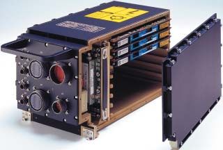
3Conduction-Cooled Chassis
Heat is dissipated through an integral baseplate
or sideplate which also supports mechanical
attachment to a suitable cold-plate
Baseplate (BBIV) or sideplate (SIV) cooled
Ideal for vetronic and naval applications where
weight is less important and a suitable cold-plate
is available
Supports high power levels
For use where mechanical noise from fans is
unacceptable
1/2ATRS-BBIV
W1 W2 L1 L3 H Weight § I/O area
1ATRL-BBIV 284 mm 348 mm 532 mm 39 mm 194 mm 23 Kg 304.8 cm2
11.18 in 13.7 in 20.94 in 1.14 in 7.63 in 50.6 lbs 47.24 in2
1ATRS-BBIV 284 mm 348 mm 348 mm 39 mm 194 mm 15.2 Kg 304.8 cm2
11.18 in 13.7 in 13.7 in 1.14 in 7.63 in 33.4 lbs 47.24 in2
1/2ATRS-BBIV 124 mm 190 mm 336 mm 39 mm 194.5 mm 6.8 Kg 118.77 cm2
4.88 in 7.48 in 13.23 in 1.14 in 7.66 in 15 lbs 18.41 in2
1/2ATRS-SIV 124 mm 135 mm 336 mm 39 mm 193.5 mm 6.3 Kg 118.77 cm2
4.88 in 5.31 in 13.23 in 1.14 in 7.62 in 13.9 lbs 18.41in2
Table 1: Conduction-Cooled Chassis Detail
NOTE: § Weight figure is for the basic chassis and backplane. It does not include the PSU, I/O connectors or I/O cabling
Figure 2: Conduction-Cooled Chassis Outline Drawing
4Blown Sidewalls
Heat generated by VMEbus modules and power
supplies is transferred by conduction to hollow
sidewall heat exchangers and hence to cooling air
Integral fan option for stand alone operation
Plenum option to duct aircraft supplied air
Lowest weight penalty for avionic applications
Fan supports vetronic and avionic applications
where a cold-plate is not available
1ATRS-FIV
W1 L1 L2 L3 L4 H Weight § I/O area
1ATRL-FIV 257.05mm 498.5mm 16.5mm 55.5mm 114mm 193.5mm 17.2 Kg * 280.5 cm2
10.12in 19.62in 0.65in 2.18in 4.49in 7.62in 37.8 lbs * 43.48 in2
1ATRL-IV 257.05mm 498.5mm 16.5mm 55.5mm 38mm 193.5mm 14.7 Kg 280.5 cm2
10.12in 19.62 0.65in 2.18in 1.5in 7.62in 32.3 lbs 43.48 in2
1ATRS-FIV 257.05mm 320.5mm 16.5mm 55.5mm 114mm 193.5mm 14.2 Kg * 280.5 cm2
10.12in 12.62 0.65in 2.18in 4.49in 7.62in 31.2 lbs * 43.48 in2
1ATRS-IV 257.05mm 320.5mm 16.5mm 55.5mm 38mm 193.5mm 11.7 Kg 280.5 cm2
10.12in 12.62inß 0.65in 2.18in 1.5in 7.62in 25.7 lbs 43.48 in2
3/4ATRS-IV 191.7mm 320.5mm 35mm 107.39mm N/A 193.5mm 5 Kg 135 cm2
7.55in 12.62in 1.38in 4.22in N/A 7.62in 11 lbs 20.93 in2
1/2ATRS-FIV 124mm 320.5mm 16.5mm 55.5mm 56mm 193.5mm 6.7 Kg 118.77 cm2
4.88in 12.62in 0.65in 2.18in 2.2in 7.62in 14.8 lbs 18.41 in2
Table 2: Blown Air Chassis Detail
NOTE: § Weight figure is for the basic chassis, fan and backplane. It does not include the PSU, I/O connectors or I/O cabling
* Figure is for DC input chassis & fan. For AC input & fan (1 or 3 phase, 400 Hz) subtract 1.6 Kg / 3.5 lbs
Figure 3: Blown Sidewalls Chassis Outline Drawing
5Liquid-Cooled Chassis
Heat generated by VMEbus modules and power
supplies is transferred by conduction to sidewall
heat exchangers and hence to cooling liquid
Handles up to 1KW of power
Low internal temperature gradients support higher
system level operating temperatures
Front panel mounted CEJN series 324 quick
disconnect couplings (alternative couplings available)
Suitable for use in aircraft/vehicle loop or stand alone
closed loop system with remote heat exchanger
1ATRL-LIV Coolants supported include water, 60/40 ethylene
glycol/water and Polyalphaolefin (PAO)
Closed loop system
with remote pump
and heat exchanger
1ATRL-LIV Coolant Flow
W1 L1 L2 H Weight § I/O area
1ATRL-LIV 257.05 mm 515 mm max 36 mm 193.5 mm 13.1 Kg 227.57 cm2
10.12 in 20.27 in max 1.42 in max 7.62 in 28.8 lbs 35.28 in2
1ATRS-LIV 257.05 mm 337 mm max 36 mm 193.5 mm 10.3 Kg 227.57 cm2
10.12 in 13.27 in max 1.42 in max 7.62 in 22.7 lbs 35.28 in2
Table 3: Conduction-Cooled Detail
NOTE: § Weight figure is for the basic chassis. It does not include the PSU, I/O connectors or cabling
Figure 4: Liquid-Cooled Chassis Outline Drawing
6Adaptation
Platform requirements often dictate a degree of I/O interface conditioning or the incorporation of specific
peripherals and it is normally more cost effective to realize such “adapted COTS” at the chassis level. For this reason
Radstone ATRs are backed up by a range of proven mechanical sub-assemblies and peripheral options that can be
used to allow standard COTS board level assemblies to be used in even the most demanding of applications.
Generally such measures include:
Power Supply configuration changes in response to
specific input voltage specifications, transient tolerance,
EMC requirements, hold-up specifications or simply
output voltage and current ratings.
Mounting Provisions. Sometimes ARINC hold downs can Above ATRS
not be used and alternatives have to be considered. For with wedgelock
example consider a Baseplate-cooled 1ATRS mounted in a mounting
tube by means of expanding wedgelocks illustrated in
figure 5.
Figure 5: Wedgelock Mounted ATR
Color and paint finishes to application requirements.
Raised lids for cable routing above VME front panels,
peripheral mounting or additional connector positions
(figure 6).
Peripherals such as FLASH disks, rotating disks, hubs and
media converters.
Contact Radstone for specific requirements
Figure 6: 1ATRL with a raised lid
Hermetic Sealing to cope with Raised Lid for cable routing above Cooling buttresses, optionally
immersion to a depth of one metre VME front panels, peripheral mount- weight reduced to suit required
ing or additional connector positions power dissipation
Application specific Internal peripheral
front panel and back- options such as cen-
plane I/O wiring tral clear equipped
FLASH disks that
allow secure data to
be erased even after
Paint colour and primary power has
finish to program been lost
requirements
Custom mounting options ATP (Acceptance Test Procedure) to prove Area for application specific
and ATR trays conformance to specification. Includes ESS front panel hardware and
testing and support for qualification program. nomenclature
Figure 7: Chassis Adaptation, showing the 1/2ATRS-BBIV
7Power Supplies
Nominal Input +5V DC +3.3V DC +12V DC -12V DC Internal Power Weight Kg Weight lbs Part Number
1ATR 28VDC 40A - - - 200W 1.49 3.3 001PSU-001000 *
28VDC 40A 10A 0.42A 0.42A 243W 1.65 3.6 001PSU-001300
1ATR 115VAC, 3 Phase 40A - - - 200W 1.57 3.5 001PSU-002000 *
115VAC, 3 Phase 40A 10A 3.6A 0.42A 281W 1.8 4.0 001PSU-002300
1ATR 115VAC, 1 Phase 40A - - - 200W 1.67 3.7 001PSU-003000 *
115VAC, 1 Phase 40A 10A 3.6A 0.42A 281W 1.9 4.2 001PSU-003300
3/4ATR 28VDC 40A - - - 200W 1.19 2.6 3/4PSU-001000 *
28VDC 40A 10A 0.42A 0.42A 243W 1.35 3.0 3/4PSU-001300
3/4ATR 115VAC, 3 Phase 40A - - - 200W 1.27 2.8 3/4PSU-002000 *
115VAC, 3 Phase 40A 10A 3.6A 0.42A 281W 1.50 3.3 3/4PSU-002300
3/4ATR 115VAC, 1 Phase 40A - - - 200W 1.37 3.0 3/4PSU-003000 *
115VAC, 1 Phase 40A 10A 3.6A 0.42A 281W 1.60 3.5 3/4PSU-003300
1/2ATR 28VDC 20A - - - 100W 0.69 1.5 1/2PSU-001000 *
28VDC 20A 10A 0.42A 0.42A 143W 0.85 1.9 1/2PSU-001300
1/2ATR 115VAC, 1 Phase 20A - - - 100W 0.67 1.5 1/2PSU-003000 *
115VAC, 1 Phase 20A 10A 3.6A 0.42A 181W 0.9 2.0 1/2PSU-003300
Table 4: Power Supply Configurations
NOTE: * Denotes PSU fitted unless otherwise agreed. All PSUs meet MIL-STD-704E. Other options such as alternative “704” standards and MIL-
STD-1275A/B are available by special order. Additionally and again by special order, PSUs can be supplied with a “hold-up” capability.
Radstone boards normally use only a +5VDC rail. Other Low pressure Storage and operation generally to MIL-E-5400
voltage rails are derived locally on each board to match (altitude) (50 000ft) for fan-cooled chassis. Higher altitudes with
reduced power levels or conduction-cooling. Also rapid
individual IC and I/O requirements. As a result, the decompression to maximum altitude
standard PSU provides only +5VDC. Additional voltage Operating -40ºC to +55ºC (level 4 boards). OR as determined by
rails are added when required. For illustration, the temperature thermal analysis of configuration
maximum configuration is also defined. Storage temp -50ºC to +100ºC (level 4 or 5 boards)
Temperature Two chamber shock test consisting of 3 cycles of transfer
Chassis Power Dissipation shock between max and min storage temperatures with a max-
imum transfer time of 5 minutes
For forced air-cooled chassis, the heat dissipation at a
Rain Simulated dripping water through leakage or condensation
given altitude is proportional to the temperature and
Humidity Up to 95% RH with varying temperature. 10 cycles 240
volumetric flow rate of the cooling air. The total chassis hrs minimum
figures given, detail operation using Level 5 cards at Salt fog Continuous exposure to mist with 5% salt solution 48 hrs
50000 feet with inlet air at 55ºC and using the standard
Sand and dust Blowing sand up to 95 ft/sec (29 m/sec)
fan or equivalent airflow from the aircraft supply.
Acceleration Structural & operational tests. Acceleration levels up to
Baseplate or Blown Sidewalls Liquid-Cooled 13.5g.
Sideplate-cooled (Forced Air-cooled)
Vibration Category 5 equipment of MIL-STD-810E vibration spec-
1ATR 450 Watts 220 Watts 1000 Watts trum fig 514.4-8 15 to 2000 Hz at 0.1g2/Hz (RMS 12g
Long approximately)
1ATR 300 Watts 150 Watts 600 Watts Shock Terminal peak saw tooth test pulse of fig 516.4-4 of MIL-
Short STD-810E at the level of 20g for 11ms for fan assisted
chassis and 40g for 11ms for baseplate/sideplate chassis.
3/4ATR - 150 Watts - Bench handling in accordance with procedure VI of
Short method 516.4 of MIL-STD-810E.
1/2ATR 150 Watts 75 Watts - EMC to MIL- Conducted emissions CE01, CE03 and CE07
Short STD-461C Conducted susceptibility CS01, CS02 and CS06
MIL-C-38999 Radiated emissions RE01 and RE02
Table 5: Power Supply Dissipation connectors Radiated susceptibility RS01, RS02 and RS03
fitted
Note: Allowance must be made for PSU inefficiency
Table 6: Generic ATR Specifications
8Ordering Information
XXX ATR X - XXX X X X X X
0= no air filter 1= with air filter
0= I/O wiring uses wirewrap pins
1= I/O through intermediate D-types (1ATR)
2= I/O wired directly (1/2ATR and 3/4ATR)
0= +5V only PSU
1= +5V and ±12V PSU
2= +5V and +3V3 PSU
3= +5V and ±12V and +3V3 PSU
0= chassis not Hermetic H= Hermetic sealing
UK
0= blown sidewalls, no fan (IV design) Radstone Technology
F= blown sidewalls with fan (FIV design) Tove Valley Business Park
B= Baseplate-cooled (BBIV design) Towcester
S= Sideplate-cooled (SIV design) Northants NN12 6PF
L= Liquid-cooled (LIV design) Telephone: +44 (0) 1327 359444
Facsimile: +44 (0) 1327 322800
001= 28 VDC primary power E-mail: sales@radstone.co.uk
002= 115 VAC, 3 phase, 400 Hz primary power
003= 115 VAC, 1 phase, 400 Hz primary power USA
005= 270 VDC Radstone Technology Corporation
Note:- Consult factory for 60Hz option 50 Tice Boulevard
Woodcliff Lake, NJ 07677-7645
S= Short L= Long Telephone: +1 (800) 368-2738
Facsimile: +1 (201) 391-2899
001= 1ATR 3/4= 3/4ATR 1/2= 1/2ATR E-mail: sales@radstone.com
Example: 1/2ATRS-001B0320 Eastern Region: +1 (201) 391-2700
North Central Region: +1 (978) 399-0195
1/2ATR Short, 28VDC primary power, baseplate conduction-cooled, non hermetic. Central Region: +1 (480) 964 5407
Western Region: +1 (909) 974-1141
Internal power +5V at 20A, +3.3V at 10A, +12V at 1.25A, -12V at 0.42A. I/O wiring
taken directly from backplane to front panel. No air filter. Fitted with blank front Helpdesk: +44 (0) 1327 322760
E-mail: support@radstone.co.uk
panel (except for power connector, handle and earth stud). No J0 connectors fitted.
http://www.radstone.com
Configured Chassis Variant Allocation CANADA
Please consult Radstone for specific adaptation or customization. The addition Interactive Circuits and Systems Ltd
5430 Canotek Road
of configuration options such as I/O wiring, PO connection or PSU hold up Ottawa, Ontario
K1J 9G2
capacitance will convert the 1/2ATRS-001B0320 chassis into a “900” series Telephone: + 1 (613) 749-9241
variant (1/2ATRS-9XXBBIV). If VME boards are added this will then become a Facsimile: + 1 (613) 749-9461
Toll Free: (US Only) 800 267-9794
configured system level product 1/2ATRS-S-9XXBBIV. E-mail: info@ics-ltd.com
http://www.ics-ltd.com
SYSCONFIG System configuration, the installation of I/O wiring, connectors and
peripherals as required. A per system charge
ESS Environmental Stress Screening. The configured chassis or system will be
exercised using system level Built-In-Test while it is subjected to thermal cycling
and vibration testing. Specification available on demand. A per system charge
ATP Functional testing of a configured system according to an agreed
Acceptance Test Program. A per system charge
THERMAL Fluent Icepak modeling software will be used to predict system level
ANALYSIS temperature gradients
SYSTEM-MTBF System level MTBF calculation using COTS board level and peripheral data
SYSTEM-DOC System level documentation to support contractual requirements
Table 7: Services
© Radstone Technology PLC 2004 Publication RT290 03/2004
This publication is issued to provide outline information only which (unless agreed by the company in writing) may not be used, RADSTONE and the Radstone symbol are registered
applied or reproduced for any purpose or form part of any order or contract or be regarded as a representation relating to prod- trademarks of Radstone Technology PLC.
ucts or services concerned. The company reserve the right to alter without notice the specification, design, price or conditions of All other trademarks are the property of their
supply of any product or service. respective owners.You can also read