3D PRINTERS & ADDITIVE MANUFACTURING - 2021 SHORT FORM - Emona ...
←
→
Page content transcription
If your browser does not render page correctly, please read the page content below
3D PRINTERS         FFF Thermoplastics
                       Carbon Fibre (Continuous Fibre)
    & ADDITIVE         Kevlar (Continuous Fibre)
MANUFACTURING          Fibreglass (Continuous Fibre)
     2021 SHORT FORM   SLA Stereolithography
                       SLS Laser Sintering
                       Electronics Printers (Aerosol Jet)
                       Biologics Printers (Aerosol Jet)
                       Multi-Layer PCB Printers
                       ADAM Metal 3D Printer
                       LENS Metal 3D Printers
                       LENS Hybrid Machine Tools

         www.emona.com.au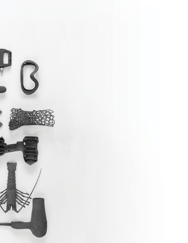
NOTES

Emona Instruments www.emona.com.au Ph: 1800 632 953
                         2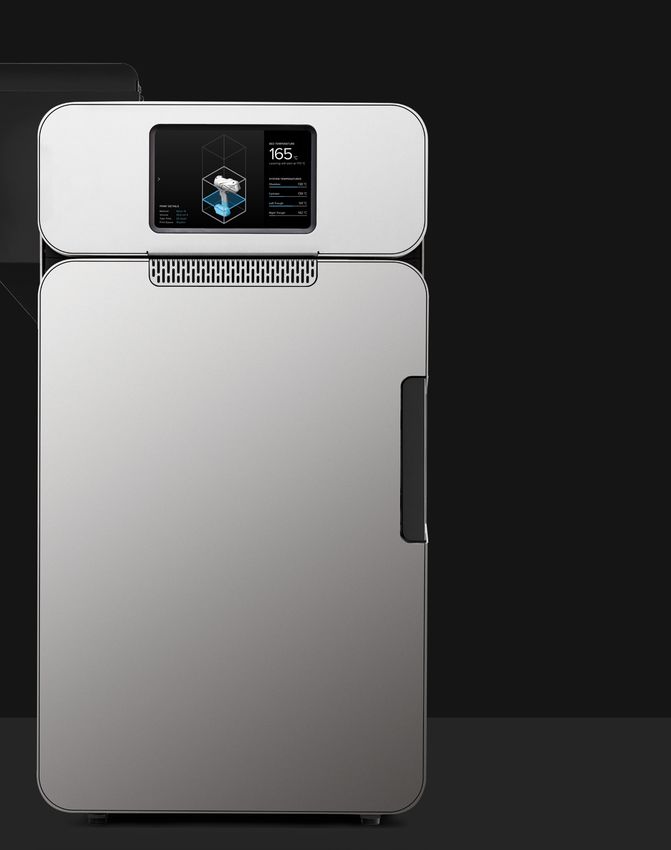
TABLE OF CONTENTS
  PRINTER          BRAND          MATERIALS         PAGE

                                 Carbon Fibre &
                                                     4
                                Composite Fibres

                                     Metals          8

                                     Plastics
                                                     11
                                 (Open Materials)

                                  Photo Resins
                                                     14
                                      (SLA)

                                  Nylon Powder
                                                     22
                                      (SLS)

                                   PCB Printer
                                                     26
                                 (Conductive ink)

                                      Metals         28
                                     (LENS)
                                  Liquids & Inks
                                   (Aerosol Jet)     34

                                   PCB Printer
                                                     38
                                   (Multi-layer)

Emona Instruments www.emona.com.au Ph: 1800 632 953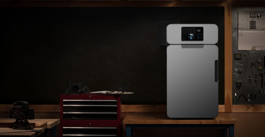
MATERIAL DESCRIPTIONS

Composites
Markforged composite printers use a base plastic matrix reinforced with continuous fibers. Combining the materials during printing
yields composite parts far stronger, stiffer, and more robust than conventional 3D printed plastics.

Plastic Matrix                                                                                       Fiber Reinforcement
In Fused Filament Fabrication (FFF), a printer heats thermoplastic filament to                       Continuous Filament Fabrication (CFF) is proprietary technology that reinforces
near melting point and extrudes it through its nozzle, building a plastic matrix                     plastic printed parts with continuous fibers on each layer of a part. Users can
layer by layer. Plastics can be reinforced by any one type of fiber.                                 control the layers reinforced, amount, orientation, and type of reinforcing fiber.

               100                                                                                                            600
                                                                                                                                            Carbon
                                                                                                                                            Fiber

                                                                               Onyx                                           500
                        80
                                                                                                                                                          HSHT                  Al 6061-T6
                                                                             Onyx FR
                                                                                                                                                          Fiberglass
                                                                                                                              400

                                                                                                      Flexural Stress (MPa)
Flexural Stress (MPa)

                        60
                                                                             ABS

                                                                                                                              300

                                                                           Nylon White
                    40                                                                                                                                                           Kevlar®
                                                                                                                              200
                                                                                                                                          Fiberglass

                    20                                                                                                        100

                                                                                                                                                                                     Onyx

                        0                                                                                                      0
                             0   0.01        0.02       0.03        0.04           0.05                                             0    0.01               0.02         0.03                0.04
                                               Flexural Strain                                                                                         Flexural Strain

                Onyx             Flexural Strength: 81 MPa                                                           Carbon Fiber               Flexural Strength: 540 MPa
Onyx is a chopped carbon fiber reinforced nylon. It’s 1.4 times stronger and                         Carbon Fiber has the highest strength-to-weight ratio of our reinforcing fibers. Six
stiffer than ABS and can be reinforced with any continuous fiber. Onyx sets the                      times stronger and eighteen times stiffer than Onyx, Carbon Fiber reinforcement
bar for surface finish, chemical resistivity, and heat tolerance.                                    is commonly used for parts that replace machined aluminum.

                Onyx FR                 Flexural Strength: 79 MPa                                                   Fiberglass              Flexural Strength: 200 MPa
Onyx FR achieves V-0 rating on the UL94 flammability test while possessing                           Fiberglass is our entry level continuous fiber, providing high strength at an
similar mechanical properties to Onyx. It’s best for applications in which flame                     accessible price. 2.5 times stronger and eight times stiffer than Onyx, Fiberglass
retardancy, light weight, and strength are required.                                                 reinforcement results in strong, robust tools.

                Nylon White                  Flexural Strength: 50 MPa                                              Kevlar®             Flexural Strength: 240 MPa
Nylon White parts are smooth, non-abrasive, and easily painted. They can                             Kevlar® possesses excellent durability, making it optimal for parts that experience
be reinforced with any continuous fiber and work best for non-marring work                           repeated and sudden loading. As stiff as fiberglass and much more ductile, it can
holding, repeated handling, and cosmetic parts.                                                      be used for a wide variety of applications.

                                                                                                                    HSHT Fiberglass                       Flexural Strength: 420 MPa
                                                                                                     High Strength High Temperature (HSHT) Fiberglass exhibits aluminum strength
                                                                                                     and high heat tolerance. Five times as strong and seven times as stiff as Onyx, it’s
                                                                                                     best used for parts loaded in high operating temperatures.

markforged.com                                                                           REV 3.1 - 5/10/2019                                           480 Pleasant St, Watertown, MA 02472
                                                                                                 4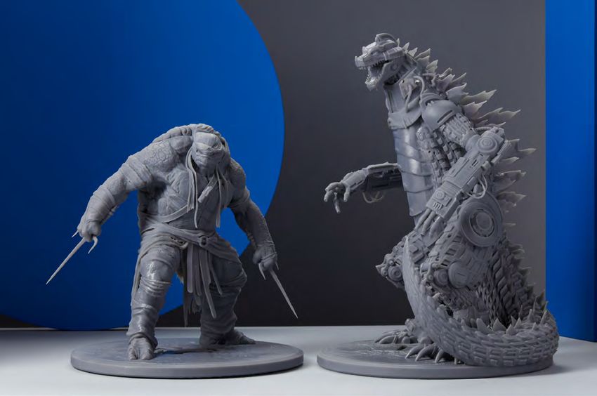
PRODUCT SPECIFICATIONS

Mark Two (Gen 2)
Replace machined aluminum tooling—jigs, jaws, and fixtures—with stronger parts for a fraction of the price. The Mark Two
combines our unique continuous carbon fiber reinforcement with workhorse reliability for versatile parts with 26x the strength
of ABS, ready same-day for use straight off the printer.

  Printer                             Process                                Fused filament fabrication, Continuous Filament Fabrication
  Properties
                                      Build Volume                           320 x 132 x 154 mm (12.6 x 5.2 x 6 in)

                                      Weight                                 16 kg (35 lbs)

                                      Machine Footprint                      584 x 330 x 355 mm (23 x 13 x 14 in)

                                      Print Bed                              Kinematic coupling — flat to within 160 μm

                                      Extrusion System                       Second-generation extruder, out-of-plastic detection

                                      Power                                  100–240 VAC, 150 W (2 A peak)

                                      RF Module                              Operating Band 2.4 GHz Wi-Fi Standards 802.11 b/g/n

  Materials                           Plastics Available                     Onyx, Nylon White

                                      Fibers Available                       Carbon fiber, fiberglass, Kevlar®, HSHT fiberglass

                                      Tensile Strength                       800 MPa (25.8x ABS, 2.6x 6061-T6 Aluminum) *

                                      Tensile Modulus                        60 GPa (26.9x ABS, 0.87x 6061-T6 Aluminum) *

  Part                                Layer Height                           100 μm default, 200 μm maximum
  Properties
                                      Infill                                 Closed cell infill: multiple geometries available

  Software                            Supplied Software                      Eiger Cloud (Other options available at cost)

                                      Security                               Two-factor authentication, org admin access, single sign-on

                                         FRONT VIEW                                                    SIDE VIEW

                                                                                             14”

                                                  23”                                                            13”

* Continuous carbon fiber data. Note: All specifications are approximate and subject to change without notice.

REV 4.3 - 2020/12/02                                                      markforged.com                                               F-PR-2027
                                                                                 5
PRODUCT SPECIFICATIONS

X7 (Gen 2)
The X7 prints industrial-grade manufacturing jigs, jaws, tools, fixtures, and end-use parts. Designed from the ground up to
survive the production floor environment and capable of printing parts stronger than machined aluminum for a fraction of the
cost, the X7 delivers unparalleled surface finish, build size, and reliability. Accelerate part production with Turbo Print, our fastest
print mode, and verify dimensional accuracy with Blacksmith adaptive manufacturing technology — only available on the X7.

  Printer                             Process                                Fused Filament Fabrication, Continuous Filament Fabrication
  Properties
                                      Build Volume                           330 x 270 x 200 mm (13 x 10.6 x 7.9 in)

                                      Weight                                 48 kg (106 lbs)

                                      Machine Footprint                      584 x 483 x 914 mm (23 x 19 x 36 in)

                                      Print Bed                              Kinematic coupling — flat to within 80 μm

                                      Laser                                  In-process inspection, active print calibration, bed leveling

                                      Extrusion System                       Second-generation extruder, out-of-plastic and out-of-fiber detection

                                      Power                                  100–240 VAC, 150 W (2 A peak)

                                      RF Module                              Operating Band 2.4 GHz Wi-Fi Standards 802.11 b/g/n

  Materials                           Plastics Available                     Onyx, Onyx FR, Onyx ESD, Nylon White

                                      Fibers Available                       Carbon fiber, fiberglass, Kevlar®, HSHT fiberglass

                                      Tensile Strength                       800 MPa (25.8x ABS, 2.6x 6061-T6 Aluminum) *

                                      Tensile Modulus                        60 GPa (26.9x ABS, 0.87x 6061-T6 Aluminum) *

  Part                                Layer Height                           100 μm default, 50 μm minimum, 250 µm maximum
  Properties
                                      Infill                                 Closed cell infill: multiple geometries available

  Software                            Eiger Cloud                            Slicer, part / build management (other options available at cost)

                                      Security                               Two-factor authentication, org admin access, single sign-on

                                      Blacksmith                             Adaptive manufacturing platform (additional purchase required)
                                         FRONT VIEW                                                    SIDE VIEW

                                                                                               36”

                                                   23”                                                           19”
* Continuous carbon fiber data. Note: All specifications are approximate and subject to change without notice.

REV 4.5 - 2021/03/04                                                      markforged.com                                                     F-PR-3012
                                                                                 6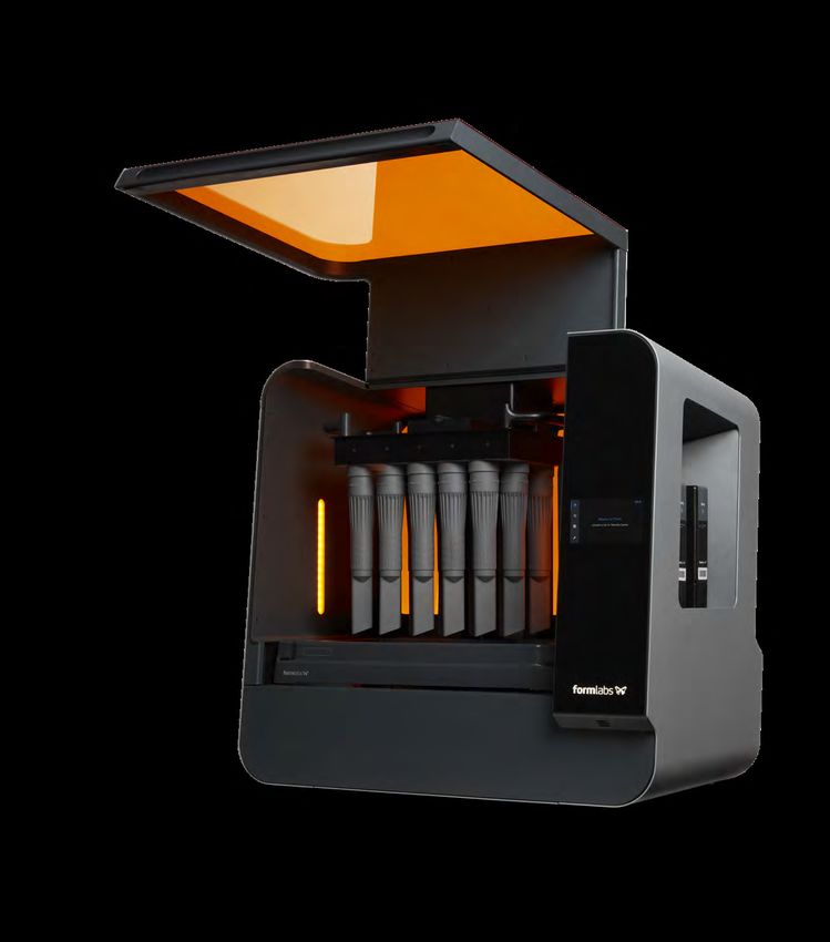
Composite Printer
Comparison

                                                      Desktop Series                                                          Industrial Series
                                                      Reliable entry level machines                                           Industrial grade machines with large build envelope
                                                      Accurate parts with good surface finish                                 Superior accuracy, resolution, and speed
                                                      Prints with standard materials                                          Full industrial material portfolio

                                                      Onyx One               Onyx Pro             Mark Two                    X3                     X5                       X7

                                                                                                                    Process

                 Fused Filament Fabrication                x                       x                       x                    x                     x                        x

            Continuous Fiber Reinforcement                                         x                       x                                          x                        x

                                                                                                                Base Materials

            Onyx (Micro carbon fiber filled nylon)         x                       x                       x                    x                     x                        x

                                      Onyx ESD                                                                                  x                     x                        x

                                        Onyx FR                                                                                 x                     x                        x

                                           Nylon                                                           x                                                                   x

                                                                                                               Continuous Fibers

                       Continuous Fiberglass                                       x                       x                                          x                        x

                    Continuous Carbon Fiber                                                                x                                                                   x

               Continuous HSHT Fiberglass                                                                  x                                                                   x

                           Continuous Kevlar®                                                              x                                                                   x

                                                                                                               Advanced Features

                     Out-of-Plastic Detection              x                       x                       x                    x                     x                        x

                       Out-of-Fiber Detection                                                                                                         x                        x

                          Fiber Jam Detection                                      x                       x                                          x                        x

                       Adaptive Bed Leveling                                                                                    x                     x                        x

                    Turbo Print (up to 4x faster)                                                                                                                              x

                               2D Layer Scan*                                                                                                                                  x

                 Blacksmith (with subscription)                                                                                                                                x

                                                                                                                   Hardware

                                  Build Volume                  320 x 132 x 154 mm (12.6 x 5.2 x 6.0 in)                      330 x 270 x 200 mm (13.0 x 10.6 x 7.9 in) (2.7x larger)

                                  Bed Flatness                 Flat to within 160 μm; Kinematic coupling                            Flat to within 80 μm; Kinematic coupling

                             Best Z Resolution                                  100 μm                                                                50 μm

                                       Supports                                                      Same material breakaway supports

                                             Infill                                            Closed-cell infill; Multiple geometries available

                                                                                                                 Specifications

                                        Storage                                                         Cloud included; Offline available

                                        Security                                         Two-factor authentication; Org admin access; Single sign-on

                                          Power                                                            100-240 VAC, 150W (2A peak)

                                         Weight                              16 kg (35 lb)                                                         48 kg (106 lb)

                                       Footprint                 584 x 330 x 355 mm (23 x 13 x 14 in)                                 584 x 483 x 914 mm (23 x 19 x 36 in)

*Laser Accuracy: z=1 μm, XY=25 μm                                                             7                                                                            markforged.com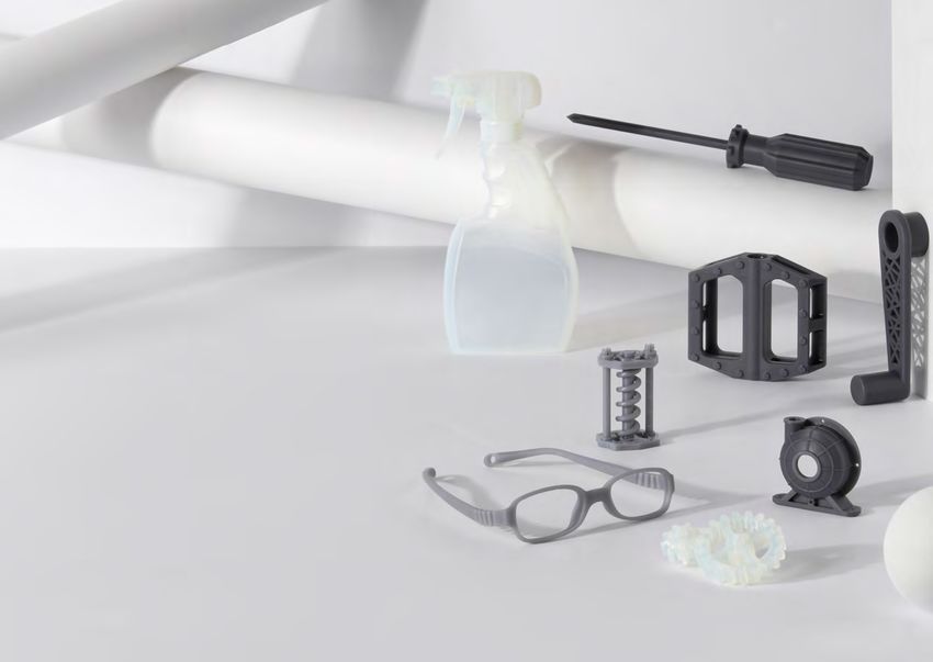
PRODUCT SPECIFICATIONS

Metal X
The Metal X is a revolutionary 3D printer that prints metal powder bound in a plastic matrix to eliminate safety risks associated
with traditional metal 3D printing methods while enabling new features like close-cell infill for reduced part weight and cost. It’s
up to 10x less expensive than alternative metal additive manufacturing technologies — and up to 100x less than traditional
fabrication technologies like machining or casting. Affordable, reliable, and easy to use, the Metal X print system gives you
everything you need to go from design to fully functional metal parts faster than ever before.

 Printer                         Process                        Metal fused filament fabrication
 Properties
                                 Build Volume                   300 x 220 x 180 mm (11.8 x 8.7 x 7.1 in)

                                 Machine Size                   575 x 467 x 1,120 mm (22.7 x 18.4 x 44.1 in), 75 kg (160 lbs)

                                 Print Chamber                  Heated

                                 Print Bed                      Heated, vacuum-sealed print sheet, auto bed leveling

                                 Print System                   Two nozzles — Metal material and release material

                                 Power Requirements             100–120 / 200-240 VAC (12A / 6A), IEC 60320 type C20

                                 RF Module                      Operating Band 2.4 GHz Wi-Fi Standards 802.11 b/g/n

 Materials                       Metal Material                 Stainless steel (17-4 PH), Tool steel (H13, A2, D2),
                                                                Inconel 625, Copper

                                 Release Material               Ceramic (consumed at 1:10 ratio to metal spools, on average)

                                 Media (Spools)                 Filament fed, bound powder

 Part                            Max Part Size                  250 x 183 x 150 mm (9.8 x 7.2 x 5.9 in), 10kg
 Properties
                                 Supports                       Metal material with ceramic release layer

                                 Layer Height                   50µm and 125µm post-sinter

 Software                        Supplied Software              Eiger Cloud (Other options available at cost)

                                 Security                       Two-factor authentication, org admin access, single sign-on

                                     FRONT VIEW                                    SIDE VIEW

                                                                             44”

                                             22”                                        18”

REV 2.5b - 2021/02/10                                       markforged.com                                                  F-PR-5000
                                                                  8
PRODUCT SPECIFICATIONS

Sinter-1
The Markforged Sinter-1 is a high-performing, high-value furnace that is ideal for small batch production. Built on 30 years
of Metal Injection Molding (MIM) technology, it’s affordable and reliable. Featuring 4,760 cm3 of active hot zone, the Sinter-1
effortlessly converts washed parts into their high-quality dense final metallic form in as few as 26 hours.

 Furnace                             Materials Supported                    Chemically debound Metal X-printed parts
 Properties
                                     Heating Element                        Kanthal

                                     Controller                             Pre-programmed automatic cycling

                                     Sinter Run Time                        26 hours*

                                     Peak Internal Temp.                    1,300° C / 2,372° F

                                     Sintering Capacity                     Rectangle w/radius top — 141 mm ID x 305 mm L (5.55 in ID x 12 in L)

                                     Sintering Workload                     3,020 cm3 (184 in3)

                                     Sinter Surface Area                    348 cm2 (53.9 in2) for single ceramic setter plate

                                     Setter Plate Dimensions                11.4cm W x 30.4cm D, (4.5in W x 12.0in D)

                                     Gas Types                              Argon, argon / hydrogen mix

                                     Retort                                 High purity refractory retort (carbon-free)

                                     RF Module                              Operating Band 2.4 GHz Wi-Fi Standards 802.11 b/g/n

 Safety &                            Environmental Req.                     External exhaust (100–150 CFM)
 Installation
                                     Power                                  200–240 V single phase 30A, recommend wiring 50A

 Physical                            External Dimensions                    1,270 x 510 x 720 mm (50 x 20 x 28 in)
 Dimensions
                                     Weight                                 136 kg (300 lbs)

                                        FRONT VIEW                                                       SIDE VIEW

                                                                                             28”

                                                  42”                                                       20”

* May vary by material. Note: All specifications are approximate and subject to change without notice.

REV 2.5 - 2020/07/20                                                      markforged.com                                                F-SR-0001
                                                                                 9
PRODUCT SPECIFICATIONS

Sinter-2
With an expansive active hot zone (19,644 cm3 / 1,199 in3), the Sinter-2 is the perfect solution for mid-volume batch production
and for larger parts. Create high-purity metal parts by using sintering technology built with a carbon-free retort. This workhorse
furnace is enabled with rapid cooling technology and can process the full range of commercial-grade metals from their washed
state into dense metal parts in as few as 30 hours.

 Furnace                             Materials Supported                      Chemically debound Metal X-printed parts
 Properties
                                     Heating Element                          Kanthal

                                     Controller                               Pre-programmed automatic cycling

                                     Sinter Run Time                          30 hours,* 17 hours (Small Parts Express Run)**

                                     Peak Internal Temp.                      1,300° C / 2,372° F

                                     Sintering Capacity                       Rectangle w/radius top — 248 mm ID x 406 mm L (9.8 in ID x 16 in L)

                                     Sintering Workload                       12,135 cm3 (741 in3)

                                     Sintering Surface Area                   1,644 cm2 (254.8 in2) for stackable ceramic setter plate

                                     Setter Plate Dimensions                  Top plate: 24.0cm W x 41.0cm D, (9.4in W x 16.1in D)
                                                                              Bottom plate: 17.0cm W x 41.0cm D, (6.7in W x 16.1in D)

                                     Gas Types                                Argon, argon / hydrogen mix

                                     Retort                                   High purity refractory retort (carbon-free)

                                     RF Module                                Operating Band 2.4 GHz Wi-Fi Standards 802.11 b/g/n

 Safety &                            Environmental Req.                       External exhaust (100–150 CFM)
 Installation
                                     Power                                    200–240 V, 3 phase (3 wire), 30 A
                                                                              346–416 V, 3 phase (4 wire), 30 A

 Physical                            External Dimensions                      1,370 x 810 x 1,520 mm (54 x 32 x 60 in)
 Dimensions
                                     Weight                                   350 kg (772 lbs)

           FRONT VIEW                                                   SIDE VIEW                                       MAX SINTER VOLUME

                                                                                                                                                                   X    406.0 mm
                                                                                                                                                                   Y    236.0 mm
                                                                                                                                                              Z2
                                                                                                                                                        Z1         Z2   114.3 mm
                                                                                                                                      R                            Z1   26.0 mm
                                                                                                                                                                   R    123.0 mm
                                                                                                                              X
                                                                                                                                               Y
                                                                    60”

                                                                                                                                      R                            X    378.0 mm
                                                                                                                                                         Z2        Y    166.0 mm
                                                                                                                                                   Z1              Z2   197.2 mm
                                                                                                                                                                   Z1   165.0 mm
                                                                                                                                                                   R    123.0 mm
                                                                                                                              X
                   48”                                                             28”                                                     Y

* May vary by material, operating environment, run mass, electrical frequency, etc. Note: All specifications are approximate and subject to change without notice.
** Express Run enabled for 17-4 PH parts where brown (washed and dried) mass totals 250 grams or less

REV 2.6 - 2020/07/20                                                      markforged.com                                                                            F-SR-0002
                                                                                10
11
12
Operating Ambient Temperature   15 - 30 °C, 10 - 90% RH non-condensing

                                        13
Form 3
Flawless Prints, Every Time.
Form 3 Tech Specs
The Next Generation of Industrial 3D Printing
Technology Dimensions Build Volume
LFS Low Force
TM
40.5 × 37.5 × 53 cm 14.5 × 14.5 × 18.5 cm
Stereolithography 15.9 × 14.8 × 20.9 in 5.7 × 5.7 × 7.3 in
Layer Thickness Optics Engine Warranty
25 - 300 microns 1 Light Processing Unit One Year Warranty included.
0.001 - 0.012 in 250 mW laser power Extended Warranty,
25 micron (0.001 in) XY Pro Service, and Enterprise
resolution Plan available.
14Family of Tough
and Durable Resins
TOUGH 2000 RESIN for Rugged Prototyping
Tough 2000 Resin is the strongest and stiffest material
in our functional family of Tough and Durable Resins.
Choose Tough 2000 Resin for prototyping strong and
sturdy parts that should not bend easily.
TOUGH 1500 RESIN for Resilient Prototyping
Tough 1500 Resin is the most resilient material in our
functional family of Tough and Durable Resins. Choose
Tough 1500 Resin for stiff and pliable parts that bend
and spring back quickly.
DURABLE RESIN for Pliable Prototyping
Durable Resin is the most pliable, impact resistant, and
lubricious material in our functional family of Tough and
Durable Resins. Choose Durable Resin for squeezable
parts and low-friction assemblies.
Solve Complex Engineering Challenges With a Range of Functional Materials
DRAFT RESIN for Truly Rapid Prototyping HIGH TEMP RESIN for High Thermal Stability
Our fastest printing material, Draft Resin is suitable for High Temp Resin offers a heat deflection temperature
printing large, bulky parts quickly. With a 300 micron (HDT) of 238 °C @ 0.45 MPa, the highest among Formlabs
layer height, it’s accurate enough to meet prototyping resins. Use it to print detailed, precise prototypes with
needs while enabling faster design iterations. high heat resistance.
GREY PRO RESIN for Versatile Prototyping RIGID RESIN for Stiffness and Precision
Grey Pro Resin offers high precision, moderate elongation, Rigid Resin is filled with glass to offer very high stiffness
and low creep. This material is great for concept modeling and a polished finish. This material is highly resistant to
and functional prototyping, especially for parts that will be deformation over time and is great for printing thin walls
handled repeatedly. and features.
ELASTIC 50A RESIN for Soft Flexible Parts FLEXIBLE 80A RESIN for Hard Flexible Parts
Our softest Engineering Resin, this 50A Shore durometer An 80A Shore durometer material for more rigid flexible
material is suitable for prototyping parts normally produced with parts with a matte-black soft-touch finish. Choose
silicone. Choose Elastic Resin for parts that will bend, stretch, Flexible Resin to create ergonomic features as part of
compress, and hold up to repeated cycles without tearing. larger assemblies.
15Maximize Material Properties with Form Cure
Form Cure provides a reliable, professional post-curing solution,
precisely controlling temperature and light to cure 3D printed parts
to their optimal performance properties.
ADVANCED HEATING
Precise temperature control is key to successful post-curing. Form Cure’s chamber
heats up to 80 °C.
BALANCED LIGHT
13 LEDs emit 405 nm light to trigger the post-curing reaction, working with the
heater to post-cure parts.
UNIFORM EXPOSURE
A rotating turntable, forced-air heating, and multi-directional LEDs uniformly
post-cure parts.
Modulus Increases with 405 nm Light and Sustained Heat
Each type of Formlabs resin requires unique post-cure settings to reach maximum mechanical properties.
The data shown here is derived from internal testing and presented for illustrative purposes. Please refer
to the official Formlabs datasheet with ASTM testing for more information.
Grey V3
Tough V4
Modulus (GPa)
Grey V3 reaches Tough V4 reaches
maximum mechanical maximum mechanical
properties after 1 hr. properties after 2 hrs.
Time Post-Cured @ 60 °C (mins)
What is Post-Curing?
During post-curing, exposure to 405 nm light triggers Post-curing improves the material properties of all resins:
the formation of additional chemical bonds within a • Standard resins increase in strength.
printed part, making the material stronger and stiffer.
• Engineering resins reach peak performance.
Heat accelerates this process and enables more
complete bond formation for a fast and highly effective • Castable resins burn out more cleanly.
post-cure resulting in optimal material properties. • Biocompatible resins require post-cure.
16Form 3L
Compact Enough for the Office,
Robust Enough for the Factory Floor
17Big Parts, Big Throughput
With a large build volume of 33.5 × 20 × 30
cm (13.2 × 7.9 × 11.8 in), you can print one large
model or many small parts in a single job.
Stop outsourcing large-scale prints. Printing Properties
Work faster with a large-format 3D printer
Low Force Stereolithography
that’s versatile enough to bring large TECHNOLOGY
(LFS)™ 3D printing
scale fabrication in-house.
BUILD VOLUME 33.5 × 20 × 30 cm
Life-sized prints for larger than (W X D X H) 13.2 × 7.9 × 11.8 in
life ideas. 25 - 300 microns
LAYER THICKNESS
The Form 3L is large enough to print human-scale .001 - .012 in
models, like a prototype of a helmet that’s ready
to try on. XY RESOLUTION 25 microns (0.001 in)
Perfectionism that scales. OPTICS ENGINE
Two 250 mW lasers
85 micron (0.0033 in) laser spot
Two precision Light Processing Units (LPU) inside the
printer achieve consistent accuracy and detail across
SUPPORTS Auto-Generated, Easy Removal
the entire build platform.
18Intuitive and Efficient
No specialized technicians required. The Form 3L offers
automatic resin dispensing, simple print preparation
software, and a thoughtfully designed interface.
HIGH-RESOLUTION TOUCHSCREEN INTERFACE
A 5.5” interactive full-color display minimizes error and eliminates
the need for constant monitoring.
AUTOMATED PRINT SETUP
Tested over millions of prints, our free print preparation software,
PreForm, automatically suggests optimal orientation, supports,
and layout, with the ability to manually refine as needed.
CONTINUOUSLY EVOLVING
We believe the best products grow better over time, and we’re
committed to continually evolving our hardware through
software improvements.
Print Around the Clock
Whether you’re packing the build volume for batch production
or printing bulky parts, the Form 3L maintains ideal print
conditions for nonstop throughput, with minimal supervision.
CLOUD MONITORING
Remotely monitor and manage your fleet of printers with the online Dashboard.
FAST-PRINTING MATERIAL
Draft Resin balances detail and speed to save time on bulky prototypes
and enable quick iteration.
IN-FIELD REPAIRS
The Light Processing Units, rollers, optics window, and other components
can be replaced in-house to ensure 24/7 uptime.
19Incredible Part Quality
Stop sacrificing on quality for large-format prints. The Form 3L provides the smooth
surface finish and fine detail that stereolithography 3D printing is known for.
SMOOTH SURFACE FINISH
Models printed on the Form 3L resemble polished injection-molded for realistic looks-like
prototyping and consumer-ready end-use part production.
CONSISTENT PRECISION
A system of lasers and mirrors ensures uniform print quality, for an XY resolution of 25 microns
across the entire build platform.
HIGH TRANSLUCENCY
With precise layer registration and smooth surface finish, translucent materials print clearer than
ever, right off the printer.
20Compare Formlabs SLA 3D Printers
FORM 3 FORM 3L FORM 3BL
Build Volume 14.5 × 14.5 × 18.5 cm 33.5 × 20 × 30 cm 33.5 × 20 × 30 cm
(W x D x H) 5.7 × 5.7 × 7.3 in 13.2 × 7.9 × 11.8 in 13.2 × 7.9 × 11.8 in
XY Resolution 25 microns 25 microns 25 microns
Biocompatible Materials – – ✓
Laser Power One 250 mW lasers Two 250 mW lasers Two 250 mW lasers
Weight 17.5 kg (38.5 lbs) 54 kg (120 lb) 54 kg (120 lb)
Printer Dimensions 40.5 × 37.5 × 53 cm 77 × 52 × 74 cm 77 × 52 × 74 cm
(W × D × H) 15.9 × 14.8 × 20.9 in 30.3 × 20.5 × 29.1 in 30.3 × 20.5 × 29.1 in
Form 3L Sample Part
This vacuum nozzle was printed straight up and down, with no supports,
directly on the build platform, and rinsed in isopropyl alcohol (IPA).
The Form 3L can print up to 20 nozzles in a single build.
Request a Grey Vacuum Nozzle sample today and a Formlabs
representative will get in touch with you.
• Smooth, matte surface finish
• Batch production of medium-sized parts
• High detail
Request a Form 3L Sample Part at
formlabs.com/request-sample-part
2122
A material that does it all
Lightweight, robust nylon is suitable for functional
prototypes and small batch manufacturing. Materials
offered will be Nylon 12 and Nylon 11, with more
materials in development.

Nylon 12: Material Properties
MEASUREMENT                            AS PRINTED ON FUSE 1          PUBLISHED VALUE
Ultimate Tensile Strength (XY)                  52 MPa                    50 MPa
Ultimate Tensile Strength (Z)                  50 MPa                     48 MPa
Tensile Modulus (XY)                           1800 MPa                   1850 MPa
Tensile Modulus (Z)                            1900 MPa                   1800 MPa
Elongation at Break (XY)                         14 %                       12 %
Elongation at Break (Z)                          7%                         6%

Feature Design Guidelines
FEATURE                                     MINIMUM VALUE          FULL STRENGTH / DEPTH
Wall Thickness                                 0.75 mm                    2.00 mm
Pin Diameter                                   1.00 mm                    2.00 mm
Hole Diameter                                  0.60 mm                    1.00 mm
Slot Width                                     0.75 mm                    3.00 mm
Moving Part Clearance                          0.25 mm                    1.00 mm

Contact sales to learn more
+1 617 702 8476        sales@formlabs.com     formlabs.com/store
                                                  23
The industrial power of selective laser
sintering (SLS) in your workshop.
)XVH6/6
Manage prototyping and production yourself,
in your space, at a tenth of the cost of existing
SLS machines.
A Complete SLS Solution
Full ecosystem includes a benchtop SLS 3D
printer, post-processing station, and intuitive
software for setting up and managing prints.
No Specialized Infrastructure
No need for a dedicated room, inert gas,
or special air handling equipment.
No Supports
Pack the build chamber full of parts,
print intricate geometries, and save time
in post-processing.
Powder Recovery System
Print with up to 50% recycled powder.
24Technical Specifications
FUSE 1
Print Engine Selective Laser Sintering
Build Volume 165 x 165 x 320 mm
Build Speed 10 mm / hour
Layer Thickness 100 µm
Material Refresh Rate Up to 50 %
Startup Time 60 minutes
Network Connectivity Ethernet or Wi-Fi
Dimensions 677 x 668 x 1059 mm
Weight 88 kg
Power Requirements 2 kW, 120 or 240 VAC
OPTICAL SYSTEM
Galvanometers Formlabs Custom
Scan Speed 2,000 mm/sec
Laser Type Fiber rated to > 10,000 hrs
Laser Wavelength 1064 nm
Laser Power 10 W
Laser Spot Size 200 µm (FWHM)
SOFTWARE
Print Preparation PreForm Desktop Software
File Type .STL or .OBJ
PRICING
Fuse 1 TBC
Fuse 1 Printer
Fuse 1 System TBC
Fuse 1 Printer
Cleaning System
Service Plan
2526
Dispense on the materials you want.
                                                           Use ridgid substrates like FR4, glass and ceramics, or
                                                           flexible films like Polyimide (Kapton) or silicone. After
                                                           printing, ink is cured at 200°C for 30 mins to ensure
                                                           excellent electrical conductivity and soldering
                                                           properties.

                                                           From initial concept to low volume runs.
                                                           Forget the hassle of stencils and dispense solder
                                                           paste on traditionally fabricated boards - A typical
                                                           board takes only 15 minutes. When it's done, mount
                                                           the components on and let the V-One's 550W heater
                                                           reflow your board right before your eyes.

                                                           Software that fits your workflow.
                                                           The V-One software processes Gerber files, so you
                                                           can use a program that you're already comfortable
                                                           with. (Eagle, Kicad, Altium, PADs, Diptrace, etc). Our
                                                           intuitive software has no learning curve and will guide
                                                           you every step of the way.

     TECHNICAL SPECIFICATIONS                                    METRIC                          IMPERIAL
      Maximum Print Area                                         135 mm x 113.5 mm               5.3" x 4.4"
      Minimum Trace Width                                        0.2 mm                          8 mil
      Minimum Pin-to-pin Pitch (Conductive Ink)                  0.8 mm                          32 mil
      Minimum Pin-to-pin Pitch (Solder Paste)                    0.5 mm                          20 mil
      Compatible Operating System                                  Windows 7, 8, 10 (64 bit). OSX 10.11+ (El Capitan)
      Compatible File Format                                                            Gerber
                                                                                                    Full list at: www.voltera.io/specs

Printed lines at 8 mil trace width                         27
                                                  Solder paste on 0603 pads                          Hand solderable pads

        sales@voltera.io                           www.voltera.io                            +1 888-381-3332
LENS
®
Metal
Additive Manufacturing
Product Family
Making Production Grade Metal Additive
Manufacturing More Affordable and Accessible
Optomec Inc. offers a full range of additive manufacturing solu-
tions for creating, enhancing and repairing metal components
with its Laser Engineered Net Shaping (LENS) systems. LENS
systems use high-powered lasers to build structures layer by
layer directly from powdered metals, alloys, ceramics or com-
posites, which result in a range of benefits:
Reduced manufacturing and materials costs
Reduced process and lead times
Reduced environmental impact
Improved product performance
Rapid design changes
28MACHINE TOOL SERIES
LENS® 500 HYBRID CONTROLLED ATMOSPHERE SYSTEM
Affordable Hybrid Machine for the Fabrication and Restoration of High Value
Metal Components.
The LENS 500 Hybrid Controlled Atmosphere System sets a
new standard in affordability and performance for titanium
and aluminum metal additive manufacturing applications.
The system incorporates an Optomec proprietary hermeti-
cally sealed Class 1 enclosure and an integrated gas purifi-
cation system that maintains oxygen and moisture levels to
below 40 ppm.
Built on a rugged cast iron CNC platform, the system features
high precision ball screws, spindle, and ATC for precision ma-
chining operations. Additive functionality is enabled with
integrated Optomec LENS Print Engine technology including
Steadyflow™ powder feeders, water-cooled LENS processing
head, and SmartAM™ closed loop controls. A high power fiber
laser and advanced Siemens controls complete the system.
Powerful Optomec software enables multi-axis build strate-
LENS 500 HY CA System. An additive only controlled gies that combine additive and subtractive operations in a
atmosphere model, LENS 500 AM CA, is also available. single tool path. Optional material starter recipes and un-
paralleled customer service and support round out the LENS
500 Hybrid Controlled Atmosphere System.
LENS 500 HY CA FEATURES LENS APPLICATIONS
Full Atmosphere Control – superior metal quality Hybrid Manufacturing
Cast Iron CNC Platform – affordable rugged base Finished Functional Prototypes
Full CNC Machining Capability – finished parts in one set-up Repair damaged/worn parts
Full LENS Additive Capability – industry proven technology Restore mis-machined components
Up to 5 Axis Motion – for complex parts/repairs Remanufacturing of legacy parts
Fiber Laser – high performance/reliability
Closed Loop Controls – part to part consistency
Common materials: Inconel Alloys, Stainless Steels, Titanium alloys
29Laser Engineered Net Shaping LENS 500 Hybrid CA System
SPECIFICATIONS LENS 500 HYBRID CA SYSTEM LENS 500 AM CA SYSTEM
Addi$ve Mode XYZ Travel (mm) 350x325x500 500x325x500
Subtrac$ve Mode XYZ Travel (mm) 500x325x500 NA
Table Size XY (mm) / Payload (kg) 600x300 / 100 600x300 /200
Posi$onal Accuracy (mm) ± 0.005 ± 0.005
Posi$onal Repeatability (mm) ± 0.0025 ± 0.0025
Rotary Table A Axis (Op$onal) Removable Removable
Addi$ve Mode XYZ Travel (mm) 200x325x500 350x325x500
AUTOMATION PLATFORM
Subtrac$ve Mode XYZ Travel (mm) 350x325x500 NA
Table Ø (mm) / Payload (kg) 170 / 100 with Tailstock 170 /100
How the LENS Process works: Trunnion (Op$onal) Removable Permanent
Addi$ve Mode XYZ Travel (mm) 350x325x300 500x325x450
The LENS process is housed in a chamber Subtrac$ve Mode XYZ Travel (mm) 500x325x300 NA
which is purged with argon such that oxygen Table Ø (mm) 120 120
and moisture levels stay below 40 parts per Maximum workpiece size Ø, H (mm) 177x300 177x450
million for LENS Hybrid CA Systems and 10 Maximum workpiece weight (kg) 35 35
parts per million for LENS Additive CA Systems. Rotary axis “C ”( degrees) 360 360
This ensures there is no impurity pickup during Tilt range “A” axis ( +/- degrees) ± 110 ± 110
deposition. CNC Controller Siemens 828 Siemens 828
Marposs Touch Probe Op$on Op$on
The LENS Deposition head delivers the laser and System Approx Weight (kg) 2500 2500
powder to the deposition zone. Metal powder is System Dimensions (mm) 1650x2050x2050 1650x2050x2050
conveyed through nozzles to the focal point of CDRH Class 1 / Air$ght Enclosure Standard Standard
the laser creating a melt pool. Argon gas is used Antechamber Ø (mm) 375 375
LENS DEPOSITION
to deliver the powder and protect the melt pool Pneuma Seal Door with Glove Access Standard / 2 Glove Ports Standard /2 Glove Ports
from contamination. Oxygen/Moisture Level (ppm) < 40 < 10
Powder Feeders Up to 4 Up to 4
Toolpaths are generated from a CAD model and Laser Power Range (W) 500 -2000 500 -2000
Closed Loop Process Control Op$on Op$on
instruct the LENS system to build or machine
2.5D Tool Path Socware Op$on Op$on
the part using standard G & M commands.
5 Axis Tool Path Socware Op$on Op$on
Material starter recipes provide pre-qualified
Tool Changer 8 Tool Umbrella Type NA
LENS processing parameters to print a variety
Tool Taper CAT 40 NA
of commonly used powders including Titanium,
MACHINING
Spindle (rpm) 8,000 NA
Inconel, and Steels.The part is built layer by lay-
Spindle Center Distance to Column Surface (mm) 381 NA
er under the control of software that monitors a
Spindle Nose to Table Surface (mm) 76 - 584 NA
variety of parameters to ensure geometric and
Spindle Motor Peak (W) 5600 NA
mechanical integrity. When complete, the part
Spindle Torque (Nm) 47.4 NA
is removed and can be heat-treated, Hot-Iso-
static Pressed, machined or finished in any
other manner.
ABOUT OPTOMEC
Optomec® is a privately-held, rapidly growing supplier of Additive Manufacturing systems. Optomec’s patented Aerosol
Jet Systems for printed electronics and LENS 3D Printers for metal components are used by industry to reduce product
cost and improve performance. Together, these unique printing solutions work with the broadest spectrum of functional
materials, ranging from electronic inks to structural metals and even biological matter. Optomec has more than 300
marquee customers around the world, targeting production applications in the Electronics, Energy, Life Sciences and
Aerospace industries. For more information about Optomec, visit http://www.optomec.com.
Optomec Inc. Tel: 505-761-8250
3911 Singer Blvd. NE Fax: 505-761-6638
Albuquerque, NM 87109 USA E-mail: sales@optomec.com
30 are trademarks of Optomec, Inc. LENS is a trademark of Sandia National Labs. 10/2018
Aerosol Jet and OptomecMACHINE TOOL SERIES
LENS®860 HYBRID CONTROLLED ATMOSPHERE SYSTEM
Larger Work Envelope & Higher Power Bring More Capabilities for Affordable,
High Quality Metal Hybrid Manufacturing.
The LENS 860 is the newest model in the affordable Optomec Hybrid
system line-up. With an 860x600x610 mm work envelope the sys-
tem enables additive and subtractive manufacturing of mid-size and
large parts. The LENS 860 comes standard with a hermetically sealed
build chamber and closed loop atmosphere controls for producing
parts with superior metal quality. The LENS 860 can be configured
with a high power 3 kW fiber laser reducing manufacturing time for
building, repairing or coating parts.
Built on a rugged CNC platform, the system features a 16 tool ATC and
an 8,000 or optional 10,000 RPM spindle for machining operations.
The base LENS 860 system is equipped with a 3-linear axis motion
system, but optionally can be delivered with a user interchangeable
LENS 860 HY CA System. An additive only controlled
rotary table and/or tilt-rotate trunnion for 4 and 5 axis for additive
atmosphere model. LENS 860 AM CA is also available. and subtractive metal processing. Additive manufacturing is enabled
with the industry proven LENS Print Engine technology including in-
tegrated Steadyflow™ powder feeders, water-cooled LENS deposition
head, and SmartAM™ closed loop process controls.
A Siemens controller manages the system’s additive and subtractive functions through an easy to use HMI. Powerful
Optomec software enables multi-axis build strategies that combine additive and subtractive operations in a single
tool path program. Optional material starter recipes and unparalleled customer service and support round out the
LENS 860 Hybrid Controlled Atmosphere System.
LENS 860 HY CA FEATURES LENS APPLICATIONS
Full Atmosphere Control – superior metal quality Hybrid Manufacturing
Large Build Volume – process larger parts Finished Functional Prototypes
Rugged CNC Base – affordable system platform Repair damaged/worn parts
Full CNC Machining Capability – finished parts in one set-up Restore mis-machined components
Full LENS Additive Capability – industry proven technology Remanufacturing of legacy parts
Up to 5 Axis Motion – for complex parts/repairs
High Power Laser – faster processing
Closed Loop Controls – part to part consistency
Common materials: Inconel Alloys, Stainless Steels, Titanium alloys
31Laser Engineered Net Shaping LENS 860 HYBRID CONTROLLED ATMOSPHERE SYSTEM
SPECIFICATIONS LENS 860 HYBRID CA SYSTEM LENS 860 AM CA SYSTEM
Addi$ve Mode XYZ Travel (mm) 598x600x610 860x600x610
Subtrac$ve Mode XYZ Travel (mm) 860x600x610 NA
Table Size XY (mm) / Payload (kg) 1000x600 / 600 1000x600 / 600
Posi$onal Accuracy (mm) ± 0.005 ± 0.005
Posi$onal Repeatability (mm) ± 0.003 ± 0.003
Rotary Table A Axis (Op$onal) Removable Removable
Addi$ve Mode XYZ Travel (mm) 598x600x610 860x600x610
Subtrac$ve Mode XYZ Travel (mm) 860x600x610 NA
Table Ø (mm) 170 170
Trunnion 170 (Op$onal) Removable Removable
How the LENS Process works: Addi$ve Mode XYZ Travel (mm) 598x600x350 860x600x460
AUTOMATION PLATFORM
Subtrac$ve Mode XYZ Travel (mm) 860x600x350 NA
Table Size Ø (mm) 170 170
The LENS process is housed in a chamber
Maximum Workpiece Size Ø, H (mm) 260 x 350 260 x 460
which is purged with argon such that oxygen Maximum Workpiece Weight Horz/Vert (kg) 100 / 50 100 / 50
and moisture levels stay below 40 parts per Rotary Axis “C ”( degrees) 360 360
million for LENS Hybrid CA Systems and 10 Tilt Range “A” axis ( +/- degrees) -15 / +115 -15 / +115
parts per million for LENS Additive CA Systems. Trunnion 250 (Op$onal) Permanent Permanent
This ensures there is no impurity pickup during Addi$ve Mode XYZ Travel (mm) 598x600x360 860x600x480
Subtrac$ve Mode XYZ Travel (mm) 860x600x360 NA
deposition.
Table Size Ø (mm) 250 250
Maximum Workpiece Size Ø, H (mm) 335x360 335x480
The LENS Deposition head delivers the laser and Maximum Workpiece Weight Horz/Vert (kg) 100 / 75 100 / 75
powder to the deposition zone. Metal powder is Rotary Axis “C ”( degrees) 360 360
conveyed through nozzles to the focal point of Tilt Range “A” axis (degrees) -30 / +120 -30 / +120
the laser creating a melt pool. Argon gas is used CNC Controller Siemens 840D Siemens 840D
Touch Probe Op$on Op$on
to deliver the powder and protect the melt pool
System Approx weight (kg) 5960 5960
from contamination. System Dimensions (mm) 4068x2735x2660 4068x2735x2660
CDRH Class 1 Air$ght Enclosure Standard Standard
Toolpaths are generated from a CAD model and Antechamber Ø (mm) 375 375
instruct the LENS system to build or machine
LENS DEPOSITION
Pneuma Seal Door with Glove Access Standard/3 Glove Ports Standard/3 Glove Ports
the part using standard G & M commands. Oxygen/Moisture Level (ppm) < 40 < 10
Standard Powder Feeders Up to 4 Up to 4
Material starter recipes provide pre-qualified
Laser Power Standard (W) 500 - 3000 500 -3000
LENS processing parameters to print a variety Closed Loop Process control Op$on Op$on
of commonly used powders including Titanium, 2.5D Tool Path Soeware Op$on Op$on
Inconel, and Steels.The part is built layer by lay- 5 Axis Tool Path Soeware Op$on Op$on
er under the control of software that monitors a Tool Changer 16 Tool Carousel NA
variety of parameters to ensure geometric and Tool Taper CAT 40 NA
MACHINING
Spindle (rpm) 8,000 NA
mechanical integrity. When complete, the part
Spindle Center Distance to Column Surface (mm) 700 NA
is removed and can be heat-treated, Hot-Iso- Spindle Nose to Table Surface (mm) 120-730 NA
static Pressed, machined or finished in any Spindle Motor Peak (W) 7000 NA
other manner. Spindle Torque (Nm) 95 NA
ABOUT OPTOMEC
Optomec® is a privately-held, rapidly growing supplier of Additive Manufacturing systems. Optomec’s patented Aerosol
Jet Systems for printed electronics and LENS 3D Printers for metal components are used by industry to reduce product
cost and improve performance. Together, these unique printing solutions work with the broadest spectrum of functional
materials, ranging from electronic inks to structural metals and even biological matter. Optomec has more than 300
marquee customers around the world, targeting production applications in the Electronics, Energy, Life Sciences and
Aerospace industries. For more information about Optomec, visit http://www.optomec.com.
Optomec Inc. Tel: 505-761-8250
3911 Singer Blvd. NE Fax: 505-761-6638
Albuquerque, NM 87109 USA E-mail: sales@optomec.com
32 are trademarks of Optomec, Inc. LENS is a trademark of Sandia National Labs. 10/2018
Aerosol Jet and OptomecThe LENS Process
LENS systems use a high-power laser together with pow-
dered metals to build fully dense structures directly from a
3D CAD solid model. The CAD model is automatically sliced
into a tool-path, which instructs the LENS machine how to
build the part. The part is constructed layer by layer under
the control of software that monitors a variety of param-
eters to ensure geometric and mechanical integrity.
MATERIALS USED COMMERCIALLY
Alloy Class Alloy Alloy Class Alloy
CP Ti Tool Steel H13, S7
Titanium Ti 6-4 13-8, 17-4
Ti 6-2-4-2 Stainless Steel 304, 316
IN625 410, 420
Aluminum 4047
IN718
Nickel Cobalt Stellite 6, 21
Waspalloy
Rene 41 Ni-WC
Carbide
Co-WC
MATERIALS USED IN R&D
Alloy Class Alloy Alloy Class Alloy
Ti 6-2-4-6 Tool Steel A-2
Titanium Ti 48-2-2 15-5PH
Ti 22AI-23Nb Stainless Steel AM355
IN690 309, 416
Hastelloy X GRCop-84
Copper
Nickel MarM 247 Cu-Ni
Rene 142 Refractories W, Mo, Nb
Ceramics Alumina Composites TiC, CrC
Optomec Inc. Tel: 505-761-8250
3911 Singer Blvd. NE Fax: 505-761-6638
33 Albuquerque, NM 87109 USA E-mail: sales@optomec.com
www.optomec.com
Aerosol Jet and Optomec are trademarks of Optomec, Inc. LENS is a trademark of Sandia National Labs. 08/2016AEROSOL JET
®
Materials FAQs
Aerosol Jet systems have the unique ability to directly print a wide range of
electronic and biological materials onto almost any substrate. The Aerosol Jet
deposition process supports a broad range of commercially available materials,
as well as custom formulations.
Materials for Aerosol Jet printing
Min/Max Printable Feature Sizes for Aerosol Jet Systems
minimum feature size is material dependent:
~10 μm features consistently printed on SiO2
Pitch between lines can be ~20 μm
Maximum feature sizes are user controllable
3 mm or greater using a wide nozzle print head
With multiple passes, features sizes are limited to the size of
the underlying substrate
Carbon Nanotube
Typic al particul ate ba sed inks for Aerosol Jet sys tems: M aterials
Solvents: SUPPORTED MATERIALS:
High boiling point / low vapor pressure (compare to ethylene glycol) Pure liquids or solvents
Solutions
Particles:
Size: 300 - 500 nanometers maximum ; < 200 nanometers preferred Dispersions
Solids content: 5 - 70 wt% See next page for Aerosol Jet printed
Multiple solid components, if used (e.g. silver and glass frit) should be material listings
equally dispersed throughout ink
Rheology
Viscosity: 1.0-1,000 cP at ambient temperature, or by heating the ink
(ink dependent)
Shear behavior: shear thinning or Newtonian – preferred;
shear thickening -unacceptable
Optomec Inc. Tel: 505-761-8250
3911 Singer Blvd. NE Fax: 505-761-6638
Albuquerque, NM 87109 USA E-mail: requestinfo@optomec.com
Aerosol Jet and Optomec are trademarks of Optomec, Inc.
www.optomec.com 34ENABLING A NEW GENERATION IN ADVANCED
PACKAGING & ASSEMBLY
Printed 3d Interconnects Printed RDL for Flip Chip BGA Printed Resistors and Printed Multi-Layer Circuit Printed 3D Interconnects
for QFN Package Capacitors Across Trench
From printed 3D Interconnects and RDLs, to embedded passives and fine feature attach, the HD Series in-line high density
deposition system is a flexible platform that meets today’s most demanding application challenges.
PRINTED 3D INTERCONNECTS
Direct printing of conformal 3D interconnects as an alternative to
wire-bonding provides wide-ranging benefits, including smaller
footprint, lower package height, reduced crosstalk and improved
mechanical reliability. The Aerosol Jet solution can produce inter-
connect traces as narrow as 25-micron to support pad pitches
down to 50-micron, and the solution is applicable to direct die
attach and die stack applications, ie: combining dedicated mem-
ory with processor.
COMPONENT AND DIE ATTACH
With its unique ability to print fine features with high viscosity
inks, the Aerosol Jet HD platform can produce high resolution ad-
hesive pads with features as small as 25-micron. This supports
conductive attach of today’s smallest die and components, with-
out the need for manual re-work, increasing overall throughput
and eliminating wasteful end-of-line clean-up steps.
PRINTED DIELECTRICS, INSULATORS AND ADHESIVES
In addition to conductive materials, the Aerosol Jet HD platform performs high resolu-
tion printing of a wide range of common non-conductive electronics materials. Appli-
cations include MEMS bonding, seal rings, local passivation, and insulative overcoats.
When coupled with conductor printing, the system can produce high density cross-
over and multi-layer circuitry.
CHIP AND BOARD LEVEL SHIELDING APPLICATIONS
The Aerosol Jet HD platform can produce precision conformal coatings on non-planar sur-
faces, enabling chip and board level EMI shielding as required by today’s mobile devic-
es. Larger nozzles enable single-pass printing of coatings measuring from millimeters
to centimeters in width, while maintaining uniform layer thickness from 100nm to 10’s
of microns. This capability, along with the HD’s fine feature printing and edge coatings of
complex packages, mean that selective exposure to contacts and ground planes are now
35
possible.LAB SYSTEMS
AEROSOL JET 5X SYSTEM ®
For 3D Printed Electronics Applications
The Aerosol Jet 5X System has been developed specifically for 3D printed
electronics applications such as fully printed antennas, sensors, and MID’s.
Driven by manufacturing requirements for flexibility and reduced
product cost, the system enables multi-axis deposition capabili-
ties facilitating R&D, rapid prototyping and low volume produc-
tion needs.
Aerosol Jet 5X is a modular solution. It comes standard with
Sprint direct write technology which is geared specifically for
printed material evaluation, prototyping, and product develop-
ment. Optionally, a Marathon print module, Optomec’s produc-
tion grade printing technology, can be added to the system
which enables low volume production runs. Automation
platforms configured with multiple Marathon print modules are
Aerosol Jet 5X System also available for high volume production needs.
Aerosol Jet supports a wide variety of functional materials, includ-
ing conductive inks, dielectrics, polymers, adhesives, etc., which can
be deposited onto planar and non-planar substrates.
The System includes Sprint interchangeable fine and wide feature
print heads capable of printing features from 10 microns to one
millimeter. The system has 5-axes of motion with a print envelope
of 200mm x 300mm x 200mm (x, y, z).
5 Axes of coordinated Print Motion
FEATURES APPLICATIONS
Features sizes ranging from ~10 microns to one millimeter 3D Antenna for Smartphones and Notepads
Dispensing support for wide variety of inks / materials Complex Molded Interconnect Devices (MIDs)
Repeatable recipe driven dispense Embedded Sensors
3D Capabilities Cost Effective Low Volume Manufacturing
CAD import eases toolpath generation
R&D to low-volume flexibility
Optomec Inc. Tel: 505-761-8250
3911 Singer Blvd. NE Fax: 505-761-6638
Albuquerque, NM 84109 USA E-mail: requestinfo@optomec.com
w w w.optomec.com 36
Aerosol Jet and Optomec are trademarks of Optomec, Inc. LENS is a trademark of Sandia National Labs. 08/2014Aerosol Jet Process Features Aerosol Jet 5X System Specifications
Minimum line width 10 um at 20 um pitch (material and surface dependent)
Single Pass Layer Thickness 100 nanometers to 2+ um
Ink Viscosity Range
Sprint Ultrasonic Atomizer 1 to 5 cP
Sprint Pneumatic Atomizer 1 to 1000 cP
Optional Product:
Marathon Print Module 50-200cP
Droplet size 1-5 um Ø
Stand-off height Up to 5mm (nozzle tip to substrate surface)
Work Area 200mm x 300mm x 200mm (x, y, z)
Motion Accuracy X, Y, Z Axes per stage ±10μm (100mm range)
How the Aerosol Jet Process Works: Motion Repeatability + 10 microns per X, Y, Z Axes
1 A liquid sample is atomized, Rotational and Pivot Axes:
creating a dense aerosol Rotational position accuracy 80 arc sec
composed of droplets with Rotational repeatability 03 arc sec
Pivot axis position accuracy 80 arc sec
diameters between approxi- Pivot axis repeatability 03 arc sec
mately 1 and 5 microns.
System dimensions 1020mm x 1375mmx 2240 mm (Does not include dimen-
sions for ErgoArm and monitor)
2 The aerosol is transported to
the deposition head using an Stand alone system weight ~835 kg
inert carrier gas. [In-flight Electrical 110/220V, 50 or 60Hz, 40 Amps (10 Amp at continuous
aerosol heating is optional]. operation, typical)
Utilities 28 LPM Nitrogen Gas
3 The aerosol is focused within Gas
the deposition head by an
annular sheath gas. The
resulting high-velocity jet is
deposited onto planar and 3D Aerosol Jet Printing Examples
substrates, creating features
ranging from 10 microns to
one millimeter in size.
Smart Phone Main Antenna Phased Array Antenna Strain Gauge on
Aluminum Structure
Courtesy: Fraunhofer IFAM
ABOUT OPTOMEC
Optomec is the world leading provider of additive manufacturing systems for high-performance application in the
Electronics, Biomedical, Photovoltaic, and Aerospace & Defense markets. These systems utilize Optomec’s patented
Aerosol Jet Printed Electronics technology and LENS power-metal fabrication technology.
Optomec Inc. Tel: 505-761-8250
3911 Singer Blvd. NE Fax: 505-761-6638
Albuquerque, NM 84109 USA E-mail: requestinfo@optomec.com
w w w.optomec.com 37
Aerosol Jet and Optomec are trademarks of Optomec, Inc. LENS is a trademark of Sandia National Labs. 08/20143D PRINTED ELECTRONICS
D R A G O N F LY 2 0 2 0 P R O 3 D P R I N T E R
TM
FOR PROFESSIONAL ELECTRONICS
SAVE TIME, MINIMIZE DEVELOPMENT RISK AND GET TO
MARKET FASTER WITHOUT SECURITY RISKS
The DragonFly 2020 Pro 3D Printer enables companies involved in electronics to take control of their development cycles by 3D
printing their own circuit boards. From proofs of concept, to design validation, to test fixtures, in-house 3D printing of multilayer
PCBs shortens design and test cycles, from months or weeks to days. Development teams can now introduce more agile
hardware development processes at every prototyping stage. This reduces time-to-market and increases innovation.
Nano Dimension’s DragonFly 2020 Pro, multi-material 3D printer brings together an extremely precise inkjet deposition printer,
dedicated nano inks, and novel software to allow designers and engineers to effortlessly print conductive and insulating
materials in one print job. The full range of PCB features can be 100% printed - including interconnections such as vias and
through-holes – without etching, drilling, plating, or waste; to produce professional, multilayer PCBs, within hours.
This advanced printing platform allows designers and engineers to develop different parts of the circuit in parallel – testing and
iterating on the fly to accelerate innovation and improve organizational performance. With the DragonFly 2020 Pro 3D Printer
many of the complexities and bottlenecks inherent in PCB prototyping are removed, allowing companies to take control of their
development cycles. The result is reduced overall development time, improved flexibility, and fewer development risks. This
enables companies to bring better electronics to the market more quickly, while keeping sensitive design information in-house
and staying on budget.
38
Headquarters: 2 Ilan Ramon st | Ness Ziona Science Park | Israel www.nano-di.com contact@nano-di.com NanoDimensiontech @3Dpcb
2 0 1 7 © N a n o Dime nsi o n Lt d . A l l r i g ht s re se r v e d , P r i nt e d N o v e m b e r 2 0 1 73D PRINTED ELECTRONICS
P R I N T M E T A L S A N D P O LY M E R S I N O N E P R I N T J O B
Nano Dimension’s extremely precise inkjet deposition system allows for simultaneous 3D printing of conductive silver
nanoparticle ink (metal) and insulating ink (dielectric polymer). This sets new standards for accuracy, complexity, and speed
in the fields of both 3D printed electronics and professional electronics development. Upon completion of a 3D print job,
there is no need for post-processing. Multi-material 3D printing is game-changing, allowing designers and engineers to
print polymers and metals together to create a functional part. This is a revolutionary approach to making electronics with
the potential to be more compact, denser, and ultimately non-planar.
AgCite TM Conductive An advanced silver nanoparticle ink designed specifically for DragonFly 2020 Pro 3D Printers.
Ink For Inkjet The size and distribution of the silver particles are optimized for the printing of highly conductive traces.
Dielectric Ink This polymer material mimics the dielectric properties of industry FR4. The ink insulates the
conductive inks, enabling the printing of the entire circuit structure. The material is stable across large
frequency ranges. Designed for compatibility with Nano Dimension’s AgCite™ conductive ink.
Decomposition Temperature (Td2, Td5) 2%-341°C, 5%-376°C
• Dielectric Constant – Dk (Permittivity) 3.2@1 MHz, 2.9@1 GHz
• Dielectric Loss – Df (Loss tangent) 0.02@1 MHz, 0.02@ 1GHz
D R A G O N F LY 2 0 2 0 P R O 3 D P R I N T E R ADDITIVE MANUFACTURING
S P E C I F I C AT I O N S (*Subject to change) OF ELECTRONICS
Deposition Technology Piezo Drop on Demand inkjet printing
Nano Dimension (TASE: NNDM, NASDAQ: NNDM) is a leading
additive manufacturing technology company. Nano Dimension
Number of Printheads 2 (One per material) is disrupting, reshaping and defining the future of how
Print Trace and Space 100 Micron (4 mil)
electronics are made. With its unique 3D printing technologies,
Nano Dimension is targeting the growing demand for
Build Volume XYZ 20 cm x 20 cm x 0.3 cm (8" x 8" x 1/8") electronic devices that require increasingly sophisticated
Software Proprietary
features and rely on printed circuit boards (PCBs). Demand
for circuitry, including PCBs - which are the heart of every
140 cm x 80 cm x 180 cm
Dimensions (55" x 31.5" x 71") (LxWxH) electronic device - covers a diverse range of industries,
Weight 500 kg (1100 lbs) TBD
including consumer electronics, medical devices, defense,
aerospace, automotive, IoT, and telecom.
Power Supply 200-240V AC; 50-60 Hz; 20A These sectors can all benefit greatly from Nano Dimension’s
Accuracy 0.001 mm (1 micron)
3D printed electronics solutions for rapid prototyping and
short-run manufacturing.
Build Plate 20 cm x 20 cm (8" x 8")
Operating System Windows, Mac, Linux
Material Compatibility Nano Dimension's conductive
and dielectric inks
Network Connectivity Ethernet TCP/IP 10/100/1000, Wi-Fi
File Compatibility Gerber (ODB++, IPC 2581 in process)
Regulatory Compliance CE/FCC/RoHS/UL (In progress)
Temp: 17°C-26°C (66°F-79°F);
Operational Environment
Relative Humidity: 28-75%
39
Headquarters: 2 Ilan Ramon st | Ness Ziona Science Park | Israel www.nano-di.com contact@nano-di.com NanoDimensiontech @3Dpcb
2 0 1 7 © N a n o Dime nsi o n Lt d . A l l r i g ht s re se r v e d , P r i nt e d N o v e m b e r 2 0 1 7EMONA Instruments Pty Ltd
SYDNEY (Head Office) MELBOURNE BRISBANE
78 Parramatta Rd Suite 4, 1175 Toorak Rd 1019 Ipswich Rd
Camperdown NSW 2050 Camberwell VIC 3124 Moorooka QLD 4105
Tel: 02 9519 3933 Tel: 03 9889 0427 Tel: 07 3392 7170
Fax: 02 9550 1378 Fax: 03 9889 0715 Fax: 07 3848 9046
PERTH ADELAIDE
213a Belmont Ave 3/26 The Parade West
Cloverdale WA 6105 Kent Town SA 5067
Tel: 08 9361 4200 Tel: 08 8363 5733
Fax: 08 9361 4300 Fax: 08 8363 5799
EMAIL
testinst@emona.com.au
GROUP WEBSITES
Electronics & Manufacturing: www.emona.com.au
Testing & Tagging: www.protag.com.au
Installation Testing: www.instaltest.com.au
TIMS Telecoms Trainer: www.tims.com.au
www.emona.com.auYou can also read