THE STARGAZER - RAPPAHANNOCK ASTRONOMY CLUB
←
→
Page content transcription
If your browser does not render page correctly, please read the page content below
The StarGazer
http://www.raclub.org/
Newsletter of the Rappahannock Astronomy Club No. 1 Vol. 10 May 2021–July 2021
Current Instrumentation and Equipment at the Mark Slade Remote
Observatory: StationONE
By Jerry Hubbell, Assistant Director, Mark Slade Remote Observatory (MSRO)
After 5+ years of operation, equipment changes, failures, and upgrades, the Mark Slade Remote Observatory
(MSRO) currently consists of three stations, with a fourth in the works. All three operational stations can be
controlled remotely over the Internet from the comfort of your home. StationONE is the subject of this article
(Figure 1.) This station was originally conceived of by Myron Wasiuta after his good friend Mark Slade passed
away and left a large variety of equipment to be dealt with. In November 2015, Myron and I started to design
StationONE using some of that equipment.
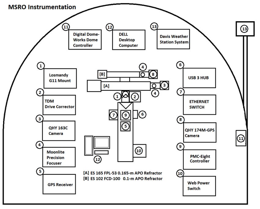
Figure 1 shows a schematic diagram of the station as it was configured about 2 years ago, We have subsequently
removed/changed some of the instruments and equipment. The equipment and systems being in use today is
described below.
Technical Innovations/ Digital Dome Works 6-Foot Observatory Dome System
The 6-foot Technical Innovations Dome gives the observatory building a classic look but is very small by design
(Figure 2). The building is constructed on an existing deck using standard 2x4 and T1-11 pre-primed siding
(bought way before today’s inflated lumber prices) and a full-size exterior door for security. The building is 7 x 7 x
7.5-feet in size and includes not only the dome itself, but also a dome skirt funded by the Rappahannock
Astronomy Club through a donation to the observatory. The dome includes the Digital DomeWorks control system
that powers the motors that slew the dome in Azimuth and raises and lowers the dome’s shutter.
Explore Scientific 5-in-1
Wireless Internet Weather
System
The original weather station installed
on StationONE was a Davis Weather
Station left to us by the Mark Slade
estate. It operated fine for 3 years, but
then started to fail. We finally removed
it from service. In the years since the
failure, we relied on Internet weather
services such as the MSRO
ClearSkyChart and Weather
Underground to give us local weather.
Earlier this year, I received the Explore
Scientific 5-in-1 Internet Weather
System that provides real-time
weather conditions at the MSRO and
uploads the data to Weather
Underground to make it available to
our local users and to those all over
the world.(Continued on page 3)
Figure 1. MSRO StationONE Instrumentation and Equipment. Credit: Jerry
Hubbell
Volume 10, Issue 1 May 2021–July 2021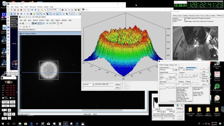
Page 2                                                                                                    The StarGazer

How to Join RAC
RAC, located in the Fredericksburg, Virginia, area,     The StarGazer
is dedicated to the advancement of public interest      May 2021–July 2021
in, and knowledge of, the science of astronomy.         Published Quarterly by Rappahannock Astronomy Club
Members share a common interest in astronomy            Editor: Linda Billard
and related fields as well as a love of observing the   Copyright 2021 by Rappahannock Astronomy Club
night sky.                                              All rights reserved

Membership is open to anyone interested in              Fair Use Notice: In accord with Title 17 U.S.C. Sections 107–
                                                        118, all copyrighted material herein is reproduced under fair use
astronomy, regardless of his/her level of knowledge.    without profit or payment and is intended solely for the benefit of
Owning a telescope is not a requirement. All you        those receiving the information for nonprofit research and
need is a desire to expand your knowledge of            educational          purposes            only.         [Reference:
astronomy. RAC members are primarily from the           https://www.law.cornell.edu/uscode/text/17/107 ]
Fredericksburg area, including, but not limited to,
the City of Fredericksburg and the counties of          Website: www.raclub.org
Stafford, Spotsylvania, King George, and Orange.        Groups.io: Members-only group. When you join RAC, you will
We also have several members who live outside           receive an invitation to join from the RAC President.
Virginia and have joined to have the opportunity to
                                                        RAC Officers
use the Mark Slade Remote Observatory (MSRO)—           Glenn Faini President
one of the benefits of joining the club.                Vacant, Vice President
                                                        Matt Scott Treasurer
RAC offers you a great opportunity to learn more        Bart Billard Secretary
about the stars, get advice on equipment purchases,     Points of Contact
and participate in community events. We meet once       Glenn Faini Public Outreach
a month and hold regular star parties each month        Glenn Holliday Scout Clinics
on the Saturday closest to the new Moon. Our            David Abbou School Programs
website, www.raclub.org is the best source of           Glenn Faini Star Parties
information on our events.                              Don Clark Web Editor & Image Gallery Editor
                                                        Don Clark Internet Administrator
                                                        Scott Busby Equipment Loan
Options for Dues Payment
                                                        Jerry Hubbell Astrophotography
                                                        Myron Wasiuta Mark Slade Remote Observatory (MSRO)
RAC annual membership is $20 per family.
Student membership is $7.50. You can now pay your dues in two ways. (For reference, the RAC membership
year is January–December.) If you join anytime in the last quarter, your membership covers the upcoming year.
Astro League dues run July to June.

    •    By Mail: Make out a check to RAC Treasurer and send it to Matthew Scott, RAC Treasurer, PO Box 752,
         Fredericksburg, VA, 22404-0752. Both new and renewing members should also print out the membership
         application here, fill it out, and return it with their payment to keep our records up to date.
    •    By PayPal: You can also pay your dues online. Simply go here, scroll down, and select the appropriate
         membership type from the dropdown box and click Pay Now. You do not need to complete an application
         because the notification the club receives of your payment will contain all the additional info needed.
         NOTE: If you pay using PayPal, your actual charge (including the PayPal usage fee) will be:
         Single/Family $21.19, Student $8.25, Single/Family & AL $28.95, Student & AL $14.98, AL Only $8.25.

 Upcoming Events*                                       Recent Events Completed
 Star Party, Caledon State Park†           August 14 Star Party, Caledon State Park                        May 8
 Star Party, Caledon State Park         September 4 Star Party, Caledon State Park                        June 5
 Star Party, Caledon State Park            October 2
 Star Party, Caledon State Park           October 30
*Our Caledon star parties are now public again! However, please check the website raclub.org for updates. To
attend a RAC meeting via Zoom, email president@raclub.org for an invitation.
†Members-only Club Picnic precedes Star Party.

Volume 10, Issue 1                                                                                 May 2021–July 2021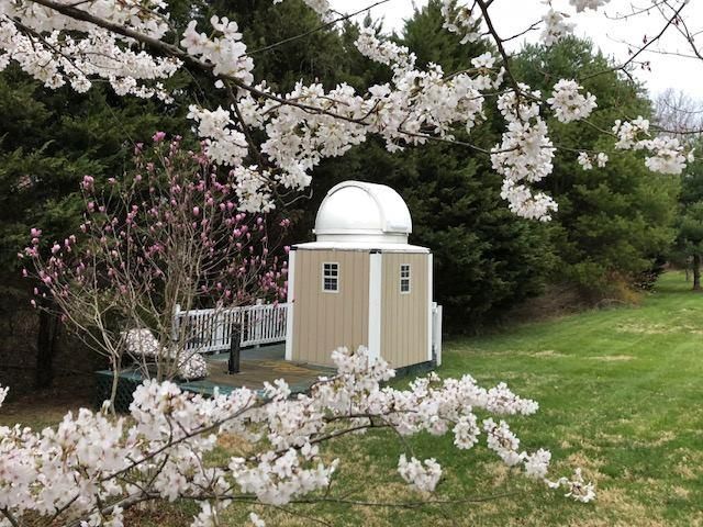
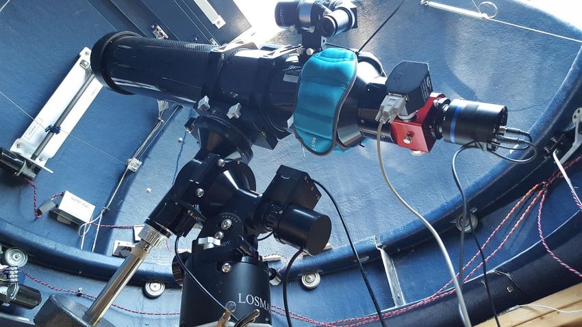
Page 3                                                                                                 The StarGazer

President’s Corner
Dear Members,

RAC Star Parties are once again open to the public. Friends, guests,
scouts, and school groups are welcome. Non-members and large groups
should contact a club officer before attending to make sure the Star Party
hasn’t been cancelled and that there will be members available to provide
guidance and assistance. There will be a Members Only picnic preceding
the August 14 Star Party.

RAC will continue to conduct its business meetings via Zoom Video
Conferencing for the foreseeable future. I send Zoom meeting invitations
to all RAC members via BCC eMail. Non-members may also participate
by sending me a request at president@raclub.org.

You can order Rappahannock Astronomy Club embroidered gear online.
Just visit www.rockytoponline.com. Under “Shop,” click “RAC.” You can purchase embroidered polos, t-shirts, and
hoodies. Orders will be processed on the last day of each month to be ready for the next General Meeting.

May God bless you with transparent skies and excellent seeing.

Glenn Faini
President

Did You Know?                                                                                      by Scott Busby
The Egyptians made precise observations of the stars as early as 3000 B.C. Their priests recognized that the
appearance of Sirius, the dog-star, in the east before sunrise was the signal that the time of the Nile floods was
approaching. They made the use of this fact to predict to the people the coming of the floods.

Source: The McDonald Telescope, Commemorating the Dedication and the Formal Opening of the McDonald
Observatory of the University of Texas May Fifth, 1939, The Caxton Company Cleveland, The Warner Swasey
Company 1939.

MSRO StationONE (from page 1)
Explore Scientific/Losmandy G11 PMC-Eight Telescope Mount System
StationONE’s mount system is the
ES/Losmandy G11 mount sold by
Explore Scientific, which is controlled
by the PMC-Eight™ Mount controller
(Figure 3). The Losmandy G11 is a
tried-and-true, high-quality, reasonably
priced mount that has been around for
more than 20 years. It is near perfect
in our application and has already
provided almost 4 years of service in
StationONE. In the interest of full
disclosure, I was hired by Explore
Scientific in 2014 to design and
develop the PMC-Eight™ system,
including the hardware, firmware, and
software used to control the mount.
The controller has very advanced           Figure 2. The Mark Slade Remote Observatory Building. Credit: Myron Wasiuta

Volume 10, Issue 1                                                                              May 2021–July 2021
Page 4 The StarGazer
features that make it very capable when used in a permanent observatory. The mount can be controlled through a
wired high-speed serial connection or wirelessly through the WiFi transceiver installed on the system. It includes
the industry standard ASCOM driver for operating the mount through a computer system.
Figure 3. Some of the Instruments installed in StationONE. Credit: Jerry Hubbell
Explore Scientific Telescope Drive Master (TDM) Drive Correction System
An additional tool installed on the ES/Losmandy G11 mount is a system called the Telescope Drive Master
(TDM). This system is an advanced drive tracking correction system that uses a high-resolution incremental
encoder installed on the Right Ascension (RA) axis. This system corrects the inherent periodic error (PE) in the
worm/wheel gear drive of the mount. PE causes the mount’s RA axis to speed up and slow down over time and
causes trailing of star images in astrophotographs.
More typical systems employ an “auto-guider” system consisting of a small telescope and camera and guiding
software that locks onto a star and sends real-time corrections (once a second or so) to the mount to mitigate the
effects of PE. The TDM operates at the higher correction rate of 5 Hz, or five times per second. This system is
basically a “turn it on and forget it” type system, whereas an auto-guider system requires a certain level of
equipment and software management and calibration to get the best performance. The TDM does not require any
extra software or time and effort to use it.
Explore Scientific 165 FPL-53 16.5-cm APO Refractor and 2.5-inch Moonlite Precision
Focuser System
The main telescope of StationONE is the Explore Scientific 165 FPL-53 16.5-cm ED APO Refractor in carbon
fiber (Figure 3). It uses the ES 3-inch 0.7x Focal Reducer/Field Flattener, which provides an effective focal length
of 851-mm with a focal ratio of f/5.1. With StationONE’s main camera system (see description below) installed,
the field of view of each image is approximately 1.3 x 0.9-degrees. We also have replaced the original focuser
with a 2.5-inch Moonlite Precision Focuser system that allows us to position the camera to within ±2 microns
(±0.000079 inches) of the telescope’s image plane. The focuser system includes a manual, push-button handset
for locally moving the focuser, and it can also be controlled by computer using the included ASCOM driver.
QHYCCD QHY163C 16-Mp Camera and Filter Wheel System
The main camera installed on the telescope is a QHYCCD, Inc. QHY163C 16-Mp CMOS TEC camera with a 7-
position filter wheel system (Figure 3). The QHY163C is a one-shot-color (OSC) CMOS chip imaging system with
a thermo-electric cooling system that allows cooling down to 40C (72F) below ambient temperature.
Volume 10, Issue 1 May 2021–July 2021
Page 5                                                                                               The StarGazer

Temperature control is important to minimize the thermal noise in the images taken with the camera. The filter
wheel allows us to not only use the OSC feature of the camera, but through a pixel binning process, acquire
filtered, monochrome images for our science work. We have developed a process to effectively use this single
camera and filter wheel for a wide range of observing projects.

GPS Receiver and NMEATime Time
The observatory computer uses a dedicated GPS receiver and the NMEATime application to provide a very
accurate time reference to timestamp image data and provide time input for controlling the mount accurately when
pointing the telescope. The GPS also gives us the precise location of the StationONE building. The NMEATime
application communicates with the GPS Receiver and constantly adjusts the computer’s internal clock to within a
few milli-seconds. This is more than enough accuracy to precisely measure the position of minor planets and to
time exoplanet transits.

Digital Loggers Web Power Switch
The Digital Loggers Web Power Switch allows us to power up and down selected equipment in the observatory
through our remote connection to the observatory over the Internet, and directly over the Internet through its
internal web server. This independent Internet connection allows us to remotely recycle the power on all the
equipment, including the computer system. We typically leave the dome controller and mount system controller
powered up, and only power up the camera system and the TDM when needed via the power switch.

Dell Inspiron 3650 Desktop Computer System
All the StationONE equipment and instruments are controlled by a Dell Inspiron 3650 Desktop Computer system
that has an Intel Core i5-6400 processor, 16GB RAM, 2-1TB system disks (main and backup), 2-6TB Data Disks
(external, USB3.0), 1Gb Ethernet adapter, and a 24-inch HD Monitor (1920x1080 resolution display). This system
stores all the data acquired over the past 5+ years of operation on the main 6-TB drive, which is replicated on the
backup 6-TB drive system. The computer system (minus the monitor) stays powered up 24x7. This system also
includes a 7-port powered USB3.0 hub to allow all the observatory instruments and equipment to communicate
with the computer system. The following instruments are attached to the USB3.0 hub: Mount Controller, TDM,
Camera, Focuser, GPS receiver, and Dome Controller.

The computer system has many different software programs and applications installed for controlling instruments,
gathering data, analyzing data, and for network and remote communications (Figure 4). We use the program
TightVNC for remotely accessing the observatory, and the main control program used is MaxIm DL. A detailed
description of all the software available will be the topic for a future article.

Figure 4. Acquiring, Analyzing Image Data, and Controlling the Observatory Using MaxIm DL. Credit:
Jerry Hubbell

Volume 10, Issue 1                                                                             May 2021–July 2021
Page 6                                                                                              The StarGazer

Observatory Network Infrastructure
The MSRO Network Infrastructure consists of several components, starting with the Comcast cable modem/router
installed in Myron’s home. The main AC power connection to the observatory also carries the network
communications through an Ethernet Power-Line adapter. The Ethernet signal is placed-on and picked-off the
power line using these adapters local to the router and at StationONE. The Ethernet is then connected to the
StationONE 5-port Ethernet Switch and connected to the observatory computer and the Web Power Switch. An
additional 30-meter Ethernet cable is run to StationTWO’s Ethernet switch, and then from there to StationTHREE.
This allows any station to access the data on any other station as needed.

As you can see, outfitting a remote observatory for reliable and high-performance operations requires several
different systems, subsystems, and components. If you would like to learn more about how the MSRO works and
are interested in using it yourself, please contact me at jhubbell@msroscience.org.

Solar System Mystery: What Is Zodiacal Light and Where Does It Come
From?
                                                     By Linda Billard

                                                     Zodiacal light—often referred to as false dawn or false
                                                     dusk—appears as a mysterious conical column of light
                                                     extending up from the horizon. It is most easily seen at a
                                                     dark location during the dark of the Moon in late February or
                                                     early March beginning 90 minutes after sunset and
                                                     continuing for about an hour and a half. You may have seen
                                                     it without knowing because it might look like light pollution
                                                     from a city or town in the distance. However, it’s much more
                                                     interesting than that.

                                                     Zodiacal light is sunlight reflected toward Earth by a cloud of
                                                     tiny dust particles orbiting the Sun. The photo shows the
                                                     zodiacal light as it appeared on March 1, 2021, in Skull
                                                     Valley, Utah. The Pleiades star cluster is visible near the top
                                                     of the light column. Mars is just below that.

                                                     Until recently, astronomers believed that asteroids or comets
                                                     brought the dust into the inner solar system. However, a
                                                     team of NASA scientists working with data collected by the
                                                     Juno spacecraft on its way to Jupiter now argue otherwise.
                                                     An instrument aboard Juno detected dust particles slamming
                                                     into the spacecraft during its journey from Earth to Jupiter.
                                                     Although the instrument was not specifically designed for
                                                     detecting these impacts, their detection offers important
Zodiacal Light. Credits: NASA/Bill Dunford           clues to the origin and orbital evolution of the dust and
resolving some mysterious variations of the zodiacal light.

As part of Juno’s magnetometer investigation, the team, led by John Leif Jørgensen, had designed the four star
trackers. To help ensure the magnetometer’s accuracy, these onboard cameras snap photos of the sky four times
a second. These snapshots help determine Juno’s orientation in space by recognizing star patterns in its images.
Jørgensen, hoping the cameras might also see an undiscovered asteroid, programmed one camera to report
anything that appeared in multiple consecutive images but wasn’t in the catalog of known celestial objects.

Jørgensen didn’t expect to see much: The star catalog accounts for nearly all objects in the sky. Consequently,
when the camera beamed thousands of images of unidentifiable objects—streaks appearing and then
mysteriously disappearing—the team was baffled. “We were looking at the images and saying, ‘What could this
be?’” Jørgensen said.

Volume 10, Issue 1                                                                            May 2021–July 2021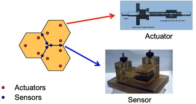
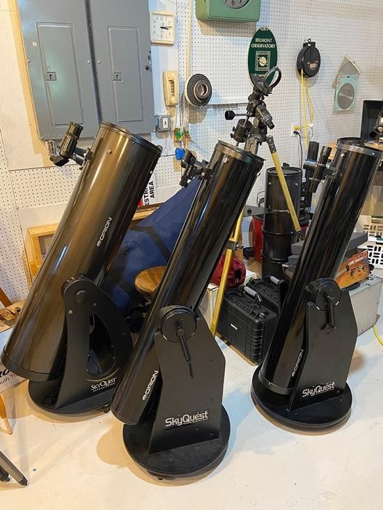
Page 7                                                                                                   The StarGazer

They considered many causes. Initially, there was the unnerving possibility that the star camera was seeing the
results of a leaking fuel tank on Juno. Jørgensen said, “The images looked like someone was shaking a dusty
tablecloth out their window.”

It wasn’t until they calculated the size and velocity of the objects that they finally realized something: The dust
grains had smacked into Juno at about 10,000 mph, chipping off submillimeter-sized pieces! As it turned out, the
spray of debris was coming from Juno’s solar panels—the biggest and most sensitive unintended dust detector
ever built.

Each piece of debris represented the impact of an interplanetary dust particle, allowing the team to determine the
distribution of dust along Juno’s journey. Juno launched in 2011. After a deep-space maneuver in the asteroid belt
in 2012, it returned to the inner solar system for an Earth gravity assist in 2013, which catapulted the spacecraft
toward Jupiter.

Jørgensen and his team noticed that most of the dust impacts occurred in the portion of the journey between
Earth and the asteroid belt, with gaps in the distribution related to the influence of Jupiter’s gravity. This was a
radical revelation. Previously, scientists had been unable to measure the distribution of these dust particles in
space. Dedicated dust detectors have limited collection areas and thus limited sensitivity to a sparse population of
dust. They mostly count the more abundant and much smaller dust particles from interstellar space. In contrast,
Juno’s solar panels have 1,000 times more collection area than most dust detectors.

Juno scientists determined that the dust cloud ended at Earth because Earth’s gravity sucks up all the dust that
gets near it. “That’s the dust we see as zodiacal light,” Jørgensen said.

The outer edge of the cloud (located at about 2 AU) ends just beyond Mars. At that point, the scientists report, the
influence of Jupiter’s gravity acts as a barrier, preventing dust particles from crossing from the inner solar system
into deep space. This same phenomenon, known as orbital resonance, also works the other way, blocking dust
originating in deep space from passing into the inner solar system.

The profound influence of the gravity barrier indicates that the dust particles are in a nearly circular orbit around
the Sun. The only object that travels in an almost circular orbit at about 2 AU is Mars, so the natural thought is
that Mars is the source of this dust.

The researchers developed a computer model to predict the light reflected by the dust cloud, dispersed by
gravitational interaction with Jupiter that scatters the dust into a thicker disk. The scattering depends only on two
quantities: the dust inclination to the ecliptic and its orbital eccentricity. When the researchers plugged in the
orbital elements of Mars, the distribution accurately predicted the telltale signature of the variation of zodiacal light
near the ecliptic. The team viewed that as confirmation of how these particles are orbiting in the solar system and
where they originate.”

While the team now has good evidence that Mars, the dustiest planet we know of, is the source of the zodiacal
light, they cannot yet explain how the dust could have escaped the grip of Martian gravity. They hope other
scientists will help them.

In the meantime, the researchers note that finding the true distribution and density of dust particles in the solar
system will help engineers design spacecraft materials that can better withstand dust impacts. This information
can also guide the design of flight paths for future spacecraft to avoid the highest concentration of particles. Tiny
particles traveling at such high velocities can gouge up to 1,000 times their mass from a spacecraft. Fortunately,
in this instance, Juno’s solar cells were undamaged because the dust impacts occurred on the back—or dark
side—of the array, which is protected by the support structure.

Featured Equipment from the RAC Lending Closet
By Scott Busby, RAC Equipment Manager

This article discusses using telescopes from our Dobsonian telescope collection. The RAC has three of these
telescopes—two 6-inch Orion© SkyQuest© models and an Orion© 10-inch with IntelliScope©.

Volume 10, Issue 1                                                                                 May 2021–July 2021
Page 8                                                                                                  The StarGazer

                                                Dobsonian telescopes have a simple, low-cost design popularized
                                                by amateur astronomer John Dobson. They are basically a
                                                Newtonian tube riding on a simple Alt/Azimuth base. Generally,
                                                Dobsonians are non-computerized systems designed for the
                                                beginning astronomer and come in apertures of 6 to 30 inches or
                                                more. As the aperture size increases, the instrument becomes
                                                heavier, bulkier, and more difficult to move about. On the other
                                                hand, the larger apertures have tremendous light-gathering ability
                                                and are very popular among experienced observers.

                                                To operate a Dobsonian, you simply rotate and elevate the scope
                                                by hand until the desired object falls within the field-of-view (FOV) of
                                                the attached and properly aligned finder scope or red-dot finder.
                                                Then use a low-power, wide-FOV eyepiece to find the target object
                                                near the center of the FOV of the main telescope. Once the object is
                                                found, you can adjust the position of the telescope to put the object
                                                in the center of view. In this position, you can experiment with
                                                various focal length eyepieces to increase or decrease
                                                magnification.

                                              I usually issue a wide-field 20–25mm eyepiece and a narrower FOV
RAC Dobsonian Telescopes. Credit:: Scott      eyepiece that offers a bit more magnification at about 8–10mm. The
Busby                                         RAC collection contains quite a few eyepieces to choose from. To
                                              determine magnification, simply use the formula: Telescope
FL/Eyepiece FL = Magnification. That’s it! For example, the 6-inch Dobsonians have a focal length of 1200 mm. If
you use 1200 mm and an EP of 20 mm, you’ll have 1200mm/20mm = 60x magnification. If you want to increase
magnification, you’ll use a shorter FL EP like a 10mm, giving you 120x magnification or an 8 mm EP giving you
150x magnification. Keep in mind that as magnification increases, the amount of light arriving at the user’s eye
goes down and the objects appear dimmer. This is not usually a problem with brighter objects like the Moon and
planets like Venus, Mars, Jupiter, and Saturn. Recently, I used one of the 6-inch Dobs with both 20 mm and 10
mm eyepieces to view the M13 globular cluster in Hercules and the Ring Nebula in Lyra. Both objects were
spectacular in the FOV of this telescope and amazed my visiting grandchildren.

For dimmer objects, such as nebulae and galaxies, you need more aperture to gather in the faint light. That’s
where the 10-inch Dob would come in handy. Also, the larger apertures permit you to use higher magnification on
objects such as the Moon and planets. The RAC’s 10-inch FL is also 1200 mm, leaving the magnification multiple
the same as the 6-inch telescopes.

The trick to becoming proficient with Dobsonian telescopes is to know the night sky. This includes the positions of
the planets and constellations during each month of the year; names of the brighter stars; and where certain
objects, such as nebulae and galaxies, live within each constellation. Star charts and a red-lens flashlight are
extremely beneficial in this regard. Alternatively, star map programs for mobile phones and tablets are readily
available, but I caution the user that your night vision may be affected by their bright screens. Another thing to
remember is that Dobsonians are manually positioned and do not automatically track objects in the sky. For that
reason, objects will tend to drift out of the FOV as the Earth rotates on its axis. Higher magnifications will intensify
this effect.

Once you master the basics, you can begin using tools to help navigate the night sky. The 10-inch Dob telescope
comes equipped with a right-angle finder-scope with crosshairs and the Orion© IntelliScope© Computerized Object
Locator. The IntelliScope© computer is easy to set up. Simply level the telescope base and turn the power on. The
handheld controller will then guide you through the alignment process, including a two-star alignment. Once you
complete the alignment, the readout on the hand controller screen will present arrows indicating what direction to
move the telescope in altitude and azimuth to arrive at the object you input into the hand controller. The hand
controller’s database has 110 Messier objects, 7,840 NGC objects, 5,386 IC objects, 8 major planets, and
provisions for 99 user-defined objects. Also accompanying the 10-inch Dob is a detailed, easy-to-understand
instruction manual.

Volume 10, Issue 1                                                                                May 2021–July 2021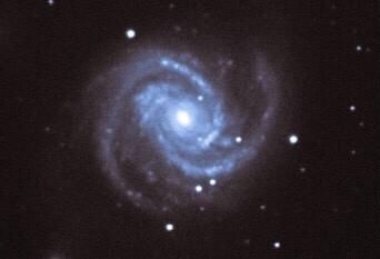
Page 9                                                                                                The StarGazer

As always and according to the rules, RAC equipment can be checked out for use by members. The process is
simple. Just notify me, the RAC Equipment Manager, via email at belmontobservatory@yahoo.com that you want
to check out a telescope or any other equipment. I may make recommendations to customize a package for you
based on your experience level. I will provide basic instructions on use, care, and maintenance of the equipment
you are checking out. The initial period of the loan is 30 days, but a phone call or email will get you an extension
of 30 days out to a maximum 90 days.

Going forward, I will highlight various RAC equipment for loan In each StarGazer quarterly issue. I will try to
describe as best I can the best use of the telescopes and other items. If you are a new member and do not have
your own telescope, the RAC equipment loaner closet is your best source to try different items to help you decide
what equipment you want to buy for your own enjoyment.

The Keck Telescopes: Birth of Segmented Mirror Technology
By Linda Billard
Recently, I watched a video presentation by Dr.
Gary Chanan, a key contributor to the development
of the segmented mirror technology that makes very
large reflectors possible. While at UC Berkeley
pursuing his Ph.D. in the 1970s, Chanan was the
student of Jerry Nelson, who would become the
father of the Keck telescopes and the originator of
the idea of the segmented mirror. Seven years later,
he joined the Nelson’s team building the Kecks. In
response to a request by Nelson and his
collaborator Terry Mast, Chanan designed the
system that aligns the segmented mirrors with each
other to form a single perfectly phased optical
surface. Today, his breakthrough technology
continues to allow construction of larger and larger      The Keck Telescopes. Credit NASA
reflecting telescopes, including several currently under construction—GMT (Giant Magellan Telescope) and ELT
(Extremely Large Telescope) in Chile, the 30-meter telescope in Hawaii, and the JWST (James Webb Space
Telescope) to be launched this fall. In his presentation, Dr. Chanan discussed the development of the Keck
telescopes, his collaboration with Jerry Nelson, and a vision of future segmented telescopes.

                 So, why is a segmented mirror used instead of a single piece of glass? There are many reasons,
                 but one of the most important is the scaling problem. As Chanan pointed out, Palomar
                 Observatory’s single 5-meter diameter mirror is 2 feet thick. You might conclude that a mirror with
                 twice the diameter (10 meters), would be twice as thick (4 feet). However, this is incorrect scaling.
Segmented        In order for the 10-meter mirror not to be subject to distortion by gravity, it would need to be not
Mirrors          twice as thick, but four times as thick (8 feet). The thickness increases by the square of the
Credit: Keck     diameter. Consequently, a single mirror of the desired size would be so heavy that it would
Observatory      difficult or impossible to move or point. Another solution to the weight problem, the honeycomb
mirrors built in the University of Arizona Mirror Lab, can be somewhat larger but still have a diameter limit of
8 meters before they become too heavy. Segmentation allows engineers to build a very large mirror whose
segments (6-foot diameter hexagons) are only 3 inches(!) thick.

So now you know that segmentation is the answer. How exactly do they do that? At least three major problems
must be solved.

How do you manufacture the segments? None of the segments has a spherical surface, which is the easiest
mirror to manufacture. To solve the problem, a number of new techniques were developed, including “stressed
mirror” polishing. Briefly, this process involves gluing levers to the perimeter of a round mirror, introducing
carefully calculated stresses using weights attached to the levers, and polishing the mirror to the usual spherical
shape with the levers in place. When the polishing is complete, the levers are removed, and the polished mirror
distorts just as desired. It can then be cut to the hexagonal shape and fit into the mirror “puzzle” with the other 35
mirrors that have had the same treatment. Chanan says this process seems like magic but works beautifully.

Volume 10, Issue 1                                                                              May 2021–July 2021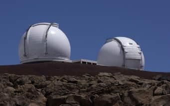
Page 10                                                                                             The StarGazer

Next, how do you control the segments? The Keck
developers designed a system of sensors and actuators,
two sensors at each edge where two segments come
together. The sensors detect the relative motion of the
two segments involved. Three actuators (glorified screws)
are attached to the back of each segment; their only job is
to adjust the relative position of the segments according
to what the sensors tell them. The sensors and actuators
are tied together through a computer system. The
software ensures that the segments work to lock
themselves together so well, Chanan was told, that you      Segmented Mirror Control System Credit: Garry Chanan
could skate around the mirror in your socks and not
disturb the relationship between the segments. During observing, the system of sensors and actuators adjusts
each segment—relative to its neighbors—to an accuracy of a millionth of an inch. This twice-per-second
adjustment effectively counters the tug of gravity.

                                            Finally, how do you align all the segments (36 in the case of each
                                            Keck telescope) so they produce the near-perfect optical surface
                                            needed for sharp images? There should be no “steps” between the
                                            segments. The mirror surface is initially mechanically aligned to
                                            within ±30 microns. However, this isn’t precise enough for optical
                                            use; the tolerances must be 1,000 times smaller. The segments
                                            must be precisely aligned to allow crisp focusing. Chanan designed
                                            the alignment system to use an interference pattern test to
                                            determine whether any pair of segments was misaligned and then
                                            adjust as necessary. The Keck telescope needs this alignment to
                                            optical tolerances about once a month to correct for slow drift in the
Initial Segmentation Installation (before
alignment) Credit: Garry Chanan             electronics of the control system. This system, designed by Chanan,
                                            is used on all the segmented telescopes in the world (and soon to
be in space), and consequently, he has been a consultant in building all telescopes that use segmented mirrors.

Even at the world’s best observatory sites, Earth-based telescopes suffer from image blurring caused by Earth’s
turbulent atmosphere. Despite their remarkable light-gathering capabilities, carefully engineered construction, and
fantastic optics, segmented mirrors are not immune to this blurring. To address this problem, the Keck telescopes,
like many large telescopes today, now use adaptive optics (AO). AO allows a deformable mirror to change shape
up to 2,000 times per second to cancel out atmospheric distortion. Consequently, the resulting images are 10
times sharper than images taken with the same telescope without AO. Successfully installing AO systems on both
Keck telescopes has made it possible for Keck astronomers to study objects in far greater detail than ever before.
(For a more detailed explanation of adaptive optics, see the April 2020 StarGazer, page 12.)

There are many examples of groundbreaking science done using the Keck telescopes with their segmented
mirrors. Here is just one. The 2020 Nobel Prize in Physics was won by Andrea Ghez of UCLA for her
revolutionary research using the Keck Observatory to provide conclusive evidence of a supermassive black hole
at the center of the Milky Way. She studied this region of the Milky Way for 25 years, observing that a number of
elliptical stellar orbits had a common focus. Whatever was at that focus had a mass 4 million times that of our
Sun, which could be nothing other than a black hole.

Note: Bart suggested I watch the referenced video as a possible subject for an article. We were surprised and
delighted to learn that Garry Chanan was a student at both Yale and Berkeley at the same times as Bart was,
although he/we never met him. However, we learned from his presentation that we did have several friends and
colleagues in common.

Volume 10, Issue 1                                                                            May 2021–July 2021
Page 11 The StarGazer Image of the Quarter: M100 By Troy Major Date/Time Taken: May 6, 2021, approximately 9–11:30 pm Brand/model telescope: Williams Optics 98 Camera: ZWO ASI294 C Exposure Info: 30-second exposures for 2-1/2 hours Post Processing/Software: Image is cropped and processed using PhotoShop Express and Lightroom According to NASA, M100 is an example of a grand-design spiral galaxy. M100 is located in the constellation Coma Berenices and is best observed during May. Its prominent spiral arms swirl around the nucleus and contain much evidence of star formation. M100’s arms also host several small black holes, including the youngest one ever observed in Earth’s cosmic neighborhood. The galaxy was discovered in 1781 by French astronomer Pierre Méchain, Charles Messier’s fellow comet hunter. M100 is located 56 million light-years from Earth and appears dim in the night sky. Its apparent magnitude of 10.1 means that, while it can be seen through small telescopes, it will appear only as a faint patch of light. Larger telescopes can resolve more details. Volume 10, Issue 1 May 2021–July 2021
You can also read