The Flexiscope: a Low Cost, Flexible, Convertible, and Modular Microscope with Automated Scanning and Micromanipulation - bioRxiv
←
→
Page content transcription
If your browser does not render page correctly, please read the page content below
bioRxiv preprint first posted online Oct. 13, 2018; doi: http://dx.doi.org/10.1101/442210. The copyright holder for this preprint
(which was not peer-reviewed) is the author/funder, who has granted bioRxiv a license to display the preprint in perpetuity.
                                    All rights reserved. No reuse allowed without permission.

     The Flexiscope: a Low Cost, Flexible, Convertible, and Modular
     Microscope with Automated Scanning and Micromanipulation.
     Amy Courtney1*, Luke M. Alvey1, George O.T. Merces1, and Mark Pickering1.

     1
         School of Medicine, University College Dublin, Ireland.

     *Correspondence: amy.courtney@ucdconnect.ie

     Abstract

     With technologies rapidly evolving, many research institutions are now opting to invest
     in costly, high-quality, specialised microscopes which are shared by many
     researchers. As a consequence, the user does not have the ability to adapt a
     microscope to their specific needs and limitations in experimental design are
     introduced. A flexible work-horse microscopy system is a valuable tool in any
     laboratory to meet the diverse needs of a research team and promote innovation in
     experimental design. We have developed the Flexiscope; a multi-functional,
     adaptable, efficient and high performance microscopy/electrophysiology system for
     everyday applications in a neurobiology laboratory. The core optical components are
     relatively constant in the three configurations described here; an upright configuration,
     an inverted configuration and an upright/electrophysiology configuration. We have
     provided a comprehensive description of the Flexiscope. We show that this method is
     capable of oblique infrared illumination imaging, multi-channel fluorescent imaging,
     and automated 3D scanning of larger specimens. Image quality is conserved across
     the three configurations of the microscope, and conversion between configurations is
     possible quickly and easily, while the motion control system can be repurposed to
     allow sub-micron computer-controlled micromanipulation. The Flexiscope provides
     similar performance and usability to commercially available systems. However, as it
     can be easily reconfigured for multiple roles, it can remove the need to purchase
     multiple microscopes, giving significant cost savings. The modular re-configurable
     nature allows the user to customise the system to their specific needs and
     adapt/upgrade the system as challenges arise.

                                                                                                                                    1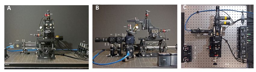
bioRxiv preprint first posted online Oct. 13, 2018; doi: http://dx.doi.org/10.1101/442210. The copyright holder for this preprint
(which was not peer-reviewed) is the author/funder, who has granted bioRxiv a license to display the preprint in perpetuity.
                                    All rights reserved. No reuse allowed without permission.

     1. Introduction
     Microscopy is widely regarded as a centrally important technique in all areas of
     biological research. The ability to resolve structures which would have otherwise been
     invisible to our eyes has contributed to the advancement of many fields. Specifically,
     the fundamental components of the brain, neurons, were identified by Golgi and Cajal
     using this technique. Neuroscience today has been propelled by the advancement of
     microscopes to perform functional measurements and connectomic studies
     (Jorgenson et al., 2015).

     With technologies rapidly evolving, many research institutions are now opting to invest
     in high-cost, high-quality, specialised microscopes which are shared by many
     researchers. As a consequence, an individual user does not have the ability to adapt
     a microscope to their specific needs and limitations in experimental design are
     introduced from the outset. Each experimental design has an optimal opto-mechanical
     configuration, and the possible variations are diverse. For example, electrophysiology
     experiments frequently require a fixed specimen stage and motion control of the
     microscope. In contrast, fluorescent or differential interference contrast (DIC)
     microscopy usually requires motion control of the specimen stage and a fixed
     microscope. Depending on the sample, an upright or inverted objective orientation
     may be optimal. Many experiments also involve coupling a microscope with other
     equipment such as a micromanipulator or incubator. Multiple microscopes would be
     required for each application despite the fact that many elements would be duplicated
     across the configurations. An adaptable work-horse microscopy system is a crucial
     and invaluable tool in any laboratory to meet the diverse needs of a research team
     and promote innovation in experimental design.

     With flexibility and funding limitations in mind, many researchers have devised
     excellent cost-saving strategies which include 3D printed microscopes and XYZ
     translators (Sharkey et al., 2016),(Baden et al., 2015) (Maia Chagas et al., 2017),
     (Stewart and Giannini, 2016), a $0.58 origami microscope (Cybulski et al., 2014), and
     modifications to old microscopes (Peidle et al., 2009), (Hernández Vera et al., 2016),
     (Stewart and Giannini, 2016). These types of systems are advantageous in the field
     or within incubators but their low cost often equates to a compromise in image quality
                                                                                                                                    2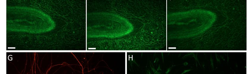
bioRxiv preprint first posted online Oct. 13, 2018; doi: http://dx.doi.org/10.1101/442210. The copyright holder for this preprint
(which was not peer-reviewed) is the author/funder, who has granted bioRxiv a license to display the preprint in perpetuity.
                                    All rights reserved. No reuse allowed without permission.

     and a lack of long term stability. In addition, many labs do not have access to these
     salvaged components or 3D printers and therefore reproducibility can be challenging.
     The components used to construct a flexible microscopy system must be readily
     available to research groups around the world, the system must cost considerably less
     than a commercial system while also maintaining a comparable image quality.

     We have designed, constructed and extensively tested a high quality, transformable
     microscopy system assembled from optical and mechanical components. The core
     optical components remain constant while alterations are made for specialised
     experimental set-ups, including objective orientation and which components are fixed
     or translating. The use of commercially available opto-mechanical elements offers
     many advantages including ease of use, reliable alignment and reproducibility (both
     within and between laboratories) due to the availability and compatibility of the parts.
     The modular, re-configurable nature allows the user to customise the system to their
     specific needs and adapt the system to the everyday diverse challenges faced when
     attempting to answer complex neurobiological questions. This system can also be
     expanded to cope with new experimental challenges and upgraded as technologies
     rapidly evolve, a considerable advantage over static commercial systems. The
     flexibility of our modular microscopy system allowed us to also implement automated
     stage scanning and image acquisition. A commercial microscope would often require
     expensive and manufacturer-specific control software. Further cost savings are
     achieved as many components can be designated for multiple applications, such as
     the actuators used to control the automated specimen stage which can be easily re-
     configured as a micromanipulator.

     We have provided a comprehensive description of a multi-functional, custom-built,
     adaptable, efficient and high-performance microscopy/electrophysiology system for
     both standard and unconventional applications in a neurobiology laboratory. This
     system encompasses the capabilities of multiple microscopes with considerable cost
     and space savings. Our system can be directly replicated or adapted to suit the needs
     any research group. Key characteristics of ‘The Flexiscope’ include: ease of use;
     upright and inverted configurations allowing multi-angle imaging; fluorescent
     microscopy; automated stage scanning; visualisation of unstained tissue; sub-micron

                                                                                                                                    3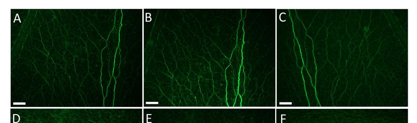
bioRxiv preprint first posted online Oct. 13, 2018; doi: http://dx.doi.org/10.1101/442210. The copyright holder for this preprint
(which was not peer-reviewed) is the author/funder, who has granted bioRxiv a license to display the preprint in perpetuity.
All rights reserved. No reuse allowed without permission.
computer-controlled micromanipulation. Implementation of this system does not
require any specialised skills or knowledge.
2. Materials and methods
2.1 Parts and Components
In order to thoroughly detail every component of the Flexiscope, each individual part
has been allocated a part designation, for use throughout this description. Table 1 lists
each part and its designation, in addition to the suppliers, supplier part number, and
cost of each part.
Table 1. Flexiscope Component List with Designators and a Cost Description.
Part Cost per unit Total cost
Component Component Description Product Code Supplier Quantity
Designator (€) (€)
Core Optical Components
Fluorescence Illumination ModuleCO1 Lime (565 nm) Mounted LED M565L3 ThorLabs 1 186.10 186.10
CO2 Blue (470 nm) Mounted LED M470L3 ThorLabs 1 236.38 236.38
CO3 UV (395 nm) Mounted LED M395L4 ThorLabs 1 249.61 249.61
CO4 LED Driver LEDD1B ThorLabs 3 258.43 775.29
CO5 Power Supply for LED and Piezo T-Cubes TPS008 ThorLabs 1 158.76 158.76
CO6 Aspheric Condenser Lens (for LED collimation) ACL2520U-DG6-A ThorLabs 3 24.43 73.29
CO7 Dichroic mounting cube CM1-DCH/M ThorLabs 2 139.36 278.72
CO8 GFP Dichroic Filter (Refl. Band = 452-490 nm, Trans. Band = 505-800 nm) MD498 ThorLabs 1 188.87 188.87
CO9 BFP Dichroic Filter (Refl. Band = 360-407 nm, Trans. Band = 425-575 nm ) MD416 ThorLabs 1 188.87 188.87
CO10 Iris Diaphragm SM1D12D ThorLabs 1 56.71 56.71
Infinite Space Module CO11 Protected Silver Tuning Mirror CCM1-P01/M ThorLabs 1 144.90 144.90
CO12 Texas Red Filter Set (Excitation, Emission, and Dichroic) MDF-TXRED ThorLabs 1 551.25 551.25
CO13 FITC Filter Set (Excitation, Emission, and Dichroic) MDF-FITC ThorLabs 1 551.25 551.25
CO14 BFP Texas Red Filter Set (Excitation, Emission, and Dichroic) MDF-BFP ThorLabs 1 551.25 551.25
CO15 Swappable Filter Set Mount DFMT1 ThorLabs 3 177.28 531.84
CO16 Filter Mount Holding Cube DFMB/M ThorLabs 1 90.85 90.85
CO17 Filter Cube Blank Top Plate DFM1C ThorLabs 1 32.40 32.40
CO18 Objective Lens Turret OT1 ThorLabs 1 262.53 262.53
CO19 4X Olympus Plan Achromat Objective (NA=0.10, WD=18.5 mm) RMS4X ThorLabs 1 167.07 167.07
CO20 20X Olympus Water Immersion Objective (NA=0.5, WD=3.5 mm) UMPLFLN20XW Masons 1 1,176.68 1,176.68
Camera Module CO21 Tube lens: Achromatic Doublet (f=150.0 mm) AC254-150-A ThorLabs 1 62.56 62.56
CO22 USB 3.0 Monochrome Camera (Flea®3 ½" FL3-U3-13Y3M-C) 86-767 Edmund Optics 1 783.75 783.75
CO23 USB 3.0 Color Camera (Grasshopper GS3-U3-15S5C-C 2/3" ) 33-533 Edmund Optics 1 1,435.09 1,435.09
CO24 1" Lens Tube to C-Mount Adapter (Male to Male) SM1A39 ThorLabs 1 18.60 18.60
CO25 USB 3.0 Locking Cable 86-770 Edmund Optics 1 23.75 23.75
CO26 Infrared LED array N/A Salvaged from CCTV Camera 1 N/A N/A
Coupling and Alignment CO27 Male to Male Tube Coupler (0.5") SM1T2 ThorLabs 6 17.55 105.30
CO28 Male to Male Tube Coupler (2") SM1T20 ThorLabs 1 18.74 18.74
CO29 Cage Cube Connector C4W-CC ThorLabs 1 43.57 43.57
CO30 Alignment Posts (Diameter = 6 mm, L = 75 mm) MS3R/M ThorLabs 4 7.10 28.40
CO31 1" Threaded Cage Plate (0.50" Thick) CP02T/M ThorLabs 1 17.90 17.90
CO32 1" Threaded Cage Plate (0.35" Thick) CP02/M ThorLabs 2 14.11 28.22
CO33 1" Lens Tube, 0.30" Thread Depth SM1L03 ThorLabs 4 10.72 42.88
CO34 1" Lens Tube, 0.5" Thread Depth SM1L05 ThorLabs 3 11.33 33.99
CO35 1" Lens Tube, 3" Thread Depth SM1L30 ThorLabs 1 21.95 21.95
CO36 1" Lens Tube, 0.31" Travel Range (Adjustable) SM1V05 ThorLabs 2 26.11 52.22
CO37 1" Lens Tube, 0.81" Travel Range (Adjustable) SM1V10 ThorLabs 1 29.34 29.34
CO38 Plastic Dust Cap for 1" Lens Tubes SM1EC2 ThorLabs 10 1.76 17.64
CO39 1" Lens Tube, 1.5" Thread Depth SM1L15 ThorLabs 1 14.27 14.27
Other components
Motion Control Components MC1 Lab Jack L490/M ThorLabs 1 527.40 527.40
MC2 Piezoelectric Actuator (13 mm Travel) PIA13 ThorLabs 4 440.12 1,760.48
MC3 T-Cube: Piezoelectric Actuator Controller TIM101 ThorLabs 1 837.90 837.90
MC4 13 mm XYZ Translation Stage MT3/M ThorLabs 1 798.21 798.21
MC5 13 mm Translation Stage Plate in One Dimension MT1A/M ThorLabs 1 356.00 356.00
MC6 25 mm XYZ Translation Stage PT3A/M ThorLabs 1 954.00 954.00
Mounting Components MO1 Optical Post (Ø12.7 mm, L = 30 mm) TR30/M-P5 ThorLabs 5 3.84 19.20
MO2 Optical Post (Ø12.7 mm, L = 20 mm) TR20/M-P5 ThorLabs 5 3.76 18.82
MO3 Optical Post (Ø12.7 mm, L = 50 mm) TR50/M-P5 ThorLabs 5 4.12 20.60
MO4 Optical Post (Ø12.7 mm, L = 75 mm) TR75/M-P5 ThorLabs 5 4.39 21.95
MO5 Optical Post (Ø12.7 mm, L = 100 mm) TR100/M-P5 ThorLabs 5 4.50 22.52
MO6 Optical Construction Post for TR75C/M (Ø12.7 mm) TR75T/M ThorLabs 1 14.90 14.90
MO7 Optical Construction Post- Variable Angle (Ø12.7 mm) TR75C/M ThorLabs 1 14.90 14.90
MO8 Post Holders (Ø12.7 mm, L=30 mm) PH30/M-P5 ThorLabs 5 6.33 31.64
MO9 Post Holders (Ø12.7 mm, L=20 mm) PH20/M-P5 ThorLabs 5 6.20 31.01
MO10 Post Holders (Ø12.7 mm, L=50 mm) PH50/M-P5 ThorLabs 5 6.79 33.96
MO11 Post Holder (Ø12.7 mm, L=75 mm) PH75/M-P5 ThorLabs 5 7.05 35.25
MO12 Mounting Base (25 mm x 75 mm x 10 mm) BA1/M-P5 ThorLabs 5 4.45 22.23
MO13 Mounting Base (25 mm x 58 mm x 10 mm) BA1S/M-P5 ThorLabs 5 3.99 19.94
MO14 Mounting Base (50 mm x 75 mm x 10 mm) BA2/M-P5 ThorLabs 5 5.80 28.98
MO15 Breadbord (100 mm x 150 mm x 12.7 mm) MB1015/M ThorLabs 1 36.90 36.90
MO16 Base Plate for Z-Axis Stage Mounting (65 mm x 65 mm x 10 mm) UBP2/M ThorLabs 1 30.87 30.87
MO17 Right-Angle Bracket AB90C/M ThorLabs 2 22.67 45.34
MO18 Microscopy Slide Holder MAX3SLH ThorLabs 1 105.69 105.69
MO19 Composite Core Optical Breadboard (600 x 600 x 28 mm) M-TD-22 Newport 1 488.70 488.70
MO20 Sorbothane Feet (Ø27.0 mm) AV4/M ThorLabs 4 4.69 18.74
Blackout Enclosure BE1 Black Hardboard (610 mm x 610 mm, 5 mm Thick) TB4 ThorLabs 3 18.81 56.43
BE2 Aluminium Extrusion (25 x 25mm, L = 600 mm) XE25L600/M ThorLabs 8 25.52 204.16
BE3 Vertical Blackout Blind (600 mm x 1700 mm) VBB060 ThorLabs 2 88.11 176.22
BE4 Black Masking Tape (50mm x 55m) T137-2.0 ThorLabs 1 13.86 13.86
Head Stage Mounting HS1 Male M6 to Female M4 Coupler AS4M6M Thorlabs 2 3.81 7.62
HS2 Male M4 to Female M3 Coupler MSA4/M Thorlabs 2 4.17 8.34
HS3 45° Brackets 100281 MakerBeam 12 0.58 6.95
HS4 Aluminum Extrusion (10x10mm, L= 100mm) 100078 MakerBeam 16 0.58 12.25
Additional configuration parts
3D printed Components 3D1 Swappable Filter Set Mount Holder 3 N/A N/A
3D2 Lens Tube - Part1 1 N/A N/A
3D3 Lens Tube - Part2 1 N/A N/A
For 3D model files, see
3D4 Camera Alignment 1 N/A N/A
3D5 Coupler: Actuator to Stepper supplementary file 3 3 N/A N/A
3D6 Y-axis Mounting 1 N/A N/A
3D7 Z-axis Mounting 1 N/A N/A
Stepper Motor XYZ-Stage S1 Arduino Uno A000066 Farnell 1 17.15 17.15
S2 CNC Shield V3.0 N/A gearbest.com 1 4.28 4.28
S3 DRV8825 Motor Drivers RB-Pol-272 RobotShop 5 1.44 7.19
S4 Jumpers 791-6454 Radionics 20 0.23 4.62
S5 NEMA17 Stepper Motor 1.8°, 0.22nm, 2.8 V, 1.33 A, 4 Wire 535-0467 Radionics 3 24.09 72.27
S6 Male USB A to Male USB B 529-8274 Radionics 1 6.21 6.21
S7 Female Shorting Link 251-8682 Radionics 10 0.03 0.27
S8 12V Power Supply 148-963 Radionics 1 12.89 12.89
S9 Spiral Binding 446-172 Radionics 1 7.21 7.21
S10 Bearings 100438 MakerBeam 10 1.40 14.00
S11 NEMA17 Stepper Bracket 100225 MakerBeam 3 3.50 10.50
S12 90° Brackets 100304 MakerBeam 12 0.58 6.95
S13 Right Angle Brackets 100326 MakerBeam 12 0.58 6.95
S14 100mm Anodised MakerBeam 100078 MakerBeam 16 0.77 12.25
S15 60mm Anodised MakerBeam 100056 MakerBeam 8 0.38 3.00
S16 40mm Anodised MakerBeam 100056 MakerBeam 8 0.38 3.00
4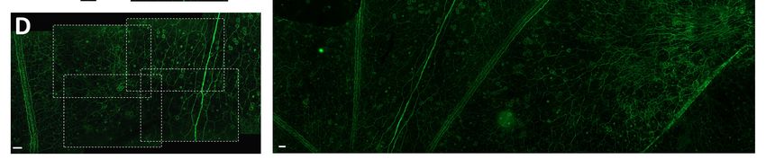
bioRxiv preprint first posted online Oct. 13, 2018; doi: http://dx.doi.org/10.1101/442210. The copyright holder for this preprint
(which was not peer-reviewed) is the author/funder, who has granted bioRxiv a license to display the preprint in perpetuity.
                                    All rights reserved. No reuse allowed without permission.

     Figure 1. Core Optical Components of the Flexiscope. The key optical and mechanical components
     constituting the light path of the Flexiscope illustrated schematically. The core optical components
     remain relatively constant with each configuration. Depending on the application, alterations are made
     to the mounting and motion control of specific elements. (A-D) illustrates the four side-views of the core
     optical components of the Flexiscope. (E) Illustrates a top-view of the core optical components of the
     Flexiscope. (F) Illustrates an orthogonal-view of the core optical components of the Flexiscope. The
     system can be divided into three functional modules; the fluorescence illumination module, the infinite
     space module, and the camera module. Component labels correspond to Table 1.

     The Core Optical Components
     We describe three sample configurations of the Flexiscope, differing in objective
     orientation, mounting and motion control. Within each configuration the core optical
     components remain relatively constant (Figure 1). The core optical components can
     be divided into three functional units: the fluorescence illumination module, the infinite
     space module and the camera module.

                                                                                                                                    5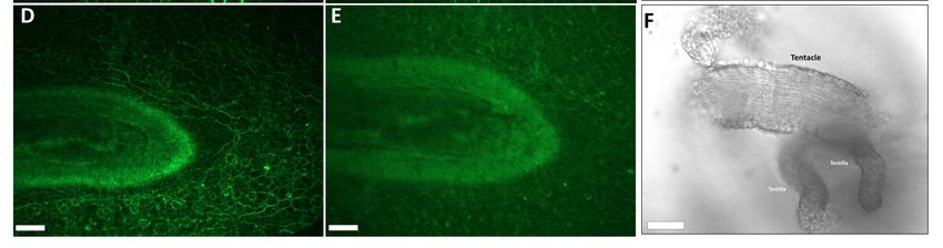
bioRxiv preprint first posted online Oct. 13, 2018; doi: http://dx.doi.org/10.1101/442210. The copyright holder for this preprint
(which was not peer-reviewed) is the author/funder, who has granted bioRxiv a license to display the preprint in perpetuity.
                                    All rights reserved. No reuse allowed without permission.

     The Fluorescence Illumination Module
     Fluorescent excitation is provided by three independent high intensity LEDs collimated
     with aspheric condenser lenses (CO6). They are combined into a single beam (Figure
     1, E and F) using two dichroic mirrors (CO8 and CO9) positioned at 45º to the light
     path in a mounting cube (CO7). The dichroic mirrors have 452-490nm reflection/505-
     800nm transmission and 360-407nm reflection/425-575nm transmission bands
     respectively. This results in the 565nm LED (CO1) passing through both dichroics, the
     470nm (CO2) reflecting off the first dichroic and passing through the second dichroic
     while the 395nm (CO3) LED reflects off the second dichroic. An iris (CO10) is placed
     after the LED module before the filter mount-holding cube (CO16) to allow for
     regulation of excitation light. The excitation light is then directed towards the filter
     mount-holding cube (CO16). The filter mount-holding cube holds the swappable filter
     set mounts (CO15), which are pre-configured to contain an excitation, emission and
     dichroic filter corresponding to either 630nm (Texas Red, CO12), 530nm (FITC, CO13)
     or 460nm (BFP, CO14) emission wavelengths. When the light passes through the
     excitation filter the dichroic mirror inside the filter set mount directs the light towards
     the objective lens. The fluorescence illumination module is a fixed entity, regardless
     of the desired application.

     The Infinite Space Module
     The Flexiscope is designed to use infinite conjugate objectives. The space between
     the tube lens and the objective (the infinite space module, Figure 1 F) can be modified
     to the user’s needs with minimal impact on optical performance. Two Infinite conjugate
     objectives, a 4X Olympus plan achromat objective (numerical aperture (NA) = 0.10,
     CO19) and a 20X Olympus water immersion objective (NA = 0.5, CO20), are coupled
     to a lens turret (CO18). The light path then travels vertically from the specimen,
     through the objective, through the filter set mount emission filter to the 45° turning
     mirror (CO11). The mirror directs the light path horizontally towards the achromatic
     doublet (CO21), which acts as a tube lens.

     The Camera Module
     The elements found immediately after the achromatic doublet lens comprise the
     camera module (Figure 1, E and F). The distance between the achromatic doublet
     lens and the camera sensor is fixed at 150mm using adjustable length lens tubes
                                                                                                                                    6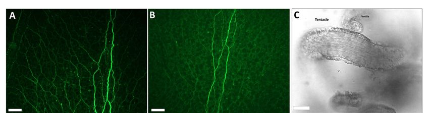
bioRxiv preprint first posted online Oct. 13, 2018; doi: http://dx.doi.org/10.1101/442210. The copyright holder for this preprint
(which was not peer-reviewed) is the author/funder, who has granted bioRxiv a license to display the preprint in perpetuity.
                                    All rights reserved. No reuse allowed without permission.

     (CO28, CO35 and CO37). Transmitted or reflected light imaging can be achieved by
     leaving the filter mount holding cube empty and enclosing the opening with the filter
     cube blank top plate (CO17). Oblique infrared illumination microscopy (OIR) uses
     infrared LEDs (CO26) at an angle above or below the specimen which allows the
     visualisation of 3D structures, resulting in images similar in appearance to DIC
     microscopy (Alix et al., 2003) (Beltran-Parrazal et al., 2014). All cameras used are c-
     mount machine vision cameras from Point Grey (now owned by FLIR). A high frame
     rate, mono, infrared sensitive camera is used for OIR (CO22). A high sensitivity, low
     noise, colour camera is used for fluorescence detection (CO23). The entire system is
     coupled together using 1” diameter lens tubes, with c-mount adaptors (CO24) used to
     couple the c-mount cameras.

     2.2 Motorised Motion Control and Automated Image Acquisition

     Our motion control system was designed to allow precise, repeatable and controllable
     movement of the specimen stage. The system can be controlled using customisable
     Matlab scripts and linked to image acquisition to permit fully automated scanning of
     larger samples.

     The Piezoelectric Stage

     Piezoelectric actuators (MC2) control the three dimensions of motion of the specimen
     stage while the Flexiscope is in the upright or inverted configuration. This allows X-
     motion (stage: right/left), Y-motion (stage: forward/backward) and Z-motion (stage:
     up/down) control. A controller module (MC3) allows computer control of the actuators.
     The APT software (ThorLabs) allows control of the actuators through the controller
     module. The ActiveX control capability in Matlab allows control of the actuators via the
     APT software. The image acquisition toolbox in Matlab is also capable of controlling
     the PointGrey cameras used on our microscope, so automated scanning is operated
     within Matlab’s workspace.

                                                                                                                                    7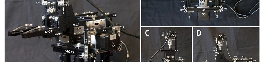
bioRxiv preprint first posted online Oct. 13, 2018; doi: http://dx.doi.org/10.1101/442210. The copyright holder for this preprint
(which was not peer-reviewed) is the author/funder, who has granted bioRxiv a license to display the preprint in perpetuity.
                                    All rights reserved. No reuse allowed without permission.

     Figure 2. Validation of Automated Specimen Stage Motion Control and Image Acquisition. (A)
     Schematic representation of the automated stage motion control workflow to acquire Z-stacks at regions
     of the sample in the X and Y direction. Many factors can influence piezoelectric actuator function and
     as the ‘step size’ values are arbitrary we acquired video recordings of the stage during motion and
     manually calculated the distance in ImageJ (Rueden et al., 2017). The following parameters were also
     set through the APT software; voltage (V): 110, drive rate (steps/sec): 500, drive accn (steps/sec/sec):
     100000 and jog rate (steps/sec):500. Load can alter piezoelectric actuator function and thus the load of
     the Z-axis is ~ 335g. (B) Validation of mean distance (µm) travelled by the Z-axis piezoelectric actuator
     when specific ‘step size’ commands (20, 50, 250, 500 and 1000) are executed repeatedly (n=15). The
     error bars indicate standard deviation and thus the intrinsic lack of repeatability of these actuators is
     evident. The resolution limit did not enable individual step distance discrimination for the 20 and 50
     ‘step sizes’ and therefore standard deviation could not be acquired. The distance travelled when the
     stage is moving up is greater than the distance travelled when the stage is moving down, despite the
     same command being sent to the actuators. (C) Example of 20 images (Z-stack) acquired at each step
     in the Z-dimension to acquire multiple in-focus planes in the tissue sample. The corresponding
     maximum intensity projection is seen alongside the Z-stack. This allows the 3D tissue to be visualised
     as a 2D image (Forster et al., 2004). (D) Illustrates the overlap in each new FOV in the X and Y
     dimension and enables image stitching. Image E is a composites of 50 maximum intensity projection
     images stitched together in ImageJ ((Preibisch et al., 2009). Scale bar for all: 50µm.

     The commands used to control the specimen stage followed a logic in which the image
     sequence of the tissue sample is considered a two dimensional array (Figure 2 A). To

                                                                                                                                    8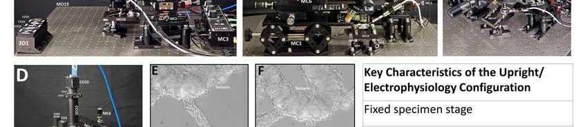
bioRxiv preprint first posted online Oct. 13, 2018; doi: http://dx.doi.org/10.1101/442210. The copyright holder for this preprint
(which was not peer-reviewed) is the author/funder, who has granted bioRxiv a license to display the preprint in perpetuity.
                                    All rights reserved. No reuse allowed without permission.

     acquire images of the whole tissue (or a region of interest) the stage is moved in the
     X-axis n-times in one direction, then moved in the Y-axis once and in the opposite
     direction in the X-axis n-times again. This cycle can then be repeated until the tissue
     has been imaged in its entirety. Each movement in X or Y dimension reveals a new
     ‘field of view’ (FOV) and a Z-stack is subsequently acquired (for code and detailed
     user guidelines see supplemental file 1).

     The Stepper Motor Automated Scanning Stage
     While the piezoelectric automated scanning stage was effective for our application
     (see 3.2) one major limitation became evident during extensive use; the piezoelectric
     actuators were slow. We therefore decided to re-configure the automated scanning
     stage to incorporate stepper motors (Supplementary Figure 2). This stage utilised 3D
     printed components to transform a manual XYZ translating stage with standard
     micrometers (MC4) into a motorised stage. Stepper motors are controlled using and
     arduino Uno running a gcode interpreter. Gcode is a standardised system for
     controlling XYZ position and movements commonly used in 3D printers and CNC
     machines. Control of the stage can then be achieved by issuing gcode commands.
     The system is controlled in Matlab in a manner similar to the piezoelectric configuration
     and the code/user guidelines are available in supplementary file 2.

     2.3 Applications Of The Flexiscope: Transforming Between Configurations
     A key design principle of a transformable microscope like the Flexiscope is that a
     single user should be able to convert from one mode of operation to another in a
     relatively short space of time, and without requiring specialised skills or tools. The core
     optical components are relatively constant in the following three modes of operation;
     the upright configuration, the inverted configuration and the upright/electrophysiology
     configuration, but differ primarily in mounting and motion control.

                                                                                                                                    9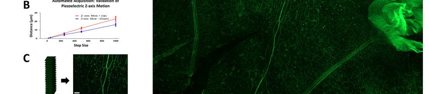
bioRxiv preprint first posted online Oct. 13, 2018; doi: http://dx.doi.org/10.1101/442210. The copyright holder for this preprint
(which was not peer-reviewed) is the author/funder, who has granted bioRxiv a license to display the preprint in perpetuity.
All rights reserved. No reuse allowed without permission.
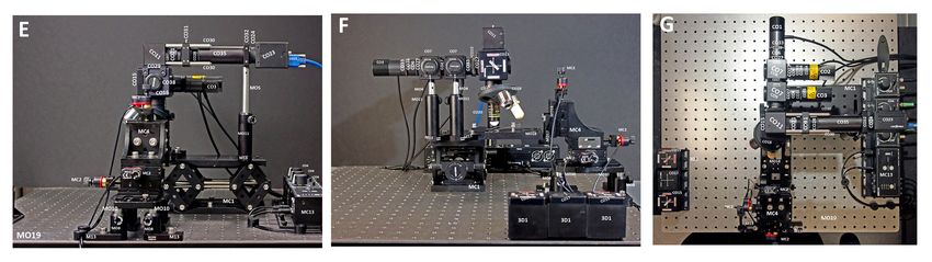
Figure 3. Comparison of the Inverted and Upright Configurations of the Flexiscope. Photographs
of the inverted (A-D) and upright (E-H) configurations illustrate the arrangement of the key optical and
mechanical components of the flexiscope into commonly used set ups. Conversion between these
configurations can be achieved in under 24 minutes (supplemental video 1). Key features of each
configuration are listed alongside the photographs. Component labels correspond to Table 1.
Inverted to Upright Configuration in Under 30 Minutes
The steps required to transition from the inverted to upright configuration (Figure 3)
involve firstly removing the XYZ specimen stage (MC4) from the jack (MC1). The jack
10bioRxiv preprint first posted online Oct. 13, 2018; doi: http://dx.doi.org/10.1101/442210. The copyright holder for this preprint
(which was not peer-reviewed) is the author/funder, who has granted bioRxiv a license to display the preprint in perpetuity.
All rights reserved. No reuse allowed without permission.
and the microscope can then be removed from the optical table (MO19). The
microscope is simply rotated 180° so that the objectives are no longer facing vertically
up, but now facing vertically down towards the optical table. Post and post holder
height on the microscope is increased (MO11, MO5, MO4). The microscopy slide
holder (MO18, MO17, MO16) on the specimen stage is reconfigured as seen in Figure
3 F. The specimen stage is mounted on a breadboard (MO15) with posts (MO10), post
holders (MO8) and mounting bases (MO12, MO13). The microscope can then be
mounted on the jack. Finally, the specimen stage and microscope/jack are aligned to
one another before fixing all components to the optical table. This process takes under
24 minutes (Supplementary Video 1). Performing these steps in reverse will result in
transformation from the upright to the inverted configuration.
Figure 4. Configuring the Flexiscope for Electrophysiology Experiments and Demonstrating OIR
Microscopy Capabilities of the System to Visualise Unstained Tissue. Photographs of the
upright/electrophysiology configuration (A-D). Component labels correspond to Table 1. The key
features of this configuration are listed alongside the photographs. The tentacles of P. pileus (gelatinous
marine invertebrate) were used to demonstrate the capability of the Flexiscope in any configuration to
implement OIR microscopy (E-G) Scale bar: 50µm. OIR microscopy to visualise the ciliary structures
and body wall of P. pileus (H) scale bar: 500µm. OIR microscopy is performed by simply positioning
Infrared LEDs obliquely above or below the tissue. No staining was required and the 3D architecture of
the tissue could be appreciated.
11bioRxiv preprint first posted online Oct. 13, 2018; doi: http://dx.doi.org/10.1101/442210. The copyright holder for this preprint
(which was not peer-reviewed) is the author/funder, who has granted bioRxiv a license to display the preprint in perpetuity.
All rights reserved. No reuse allowed without permission.
The Upright/Electrophysiology Configuration: Manual Microscope Translation
with a Four-Dimension Micromanipulator Controlled by Piezoelectric Actuators
The third configuration (upright/electrophysiology configuration, Figure 4.) requires
some alterations to core optical components. For ease of mounting, in this
configuration the light path is aligned vertically. To achieve this, the 45° mirror in the
infinite space module is replaced with a 1.5” straight lens tube (CO39). In addition, the
fluorescence illumination module is rotated so that the side mounted LEDs are
oriented upwards. This modification is only required to facilitate mounting to the optical
breadboard (MO15). The whole microscope is mounted to this breadboard which is in
turn mounted vertically to a manual XYZ translation stage (MC6). The microscope
components are mounted to the jack. A fixed specimen stage is mounted directly to
the optical table.
Figure 5. Micromanipulator Validation: Piezoelectric Actuation in Four Dimensions withbioRxiv preprint first posted online Oct. 13, 2018; doi: http://dx.doi.org/10.1101/442210. The copyright holder for this preprint
(which was not peer-reviewed) is the author/funder, who has granted bioRxiv a license to display the preprint in perpetuity.
All rights reserved. No reuse allowed without permission.
especially when computer controlled systems are required. The piezoelectric
actuators which were previously configured as a specimen stage are now re-
configured as a micromanipulator (Figure 5). A fourth dimension (approach-axis or A-
axis, MC5) is incorporated into the stage and the angle of approach can be manually
adjusted, depending on the objective configuration or to reduce the length of electrode
in solution (minimise electrical noise). The electrode holder is mounted to the
micromanipulator using Makerbeam and Thorlabs components (HS1-4). This
configuration therefore involves a fixed specimen stage, manual microscope motion in
three dimensions and four axis micromanipulation withbioRxiv preprint first posted online Oct. 13, 2018; doi: http://dx.doi.org/10.1101/442210. The copyright holder for this preprint
(which was not peer-reviewed) is the author/funder, who has granted bioRxiv a license to display the preprint in perpetuity.
All rights reserved. No reuse allowed without permission.
tentacular sheaths, mouth and pharynx) were teased away with Dumont HP Tweezers
(5 Carbon steel 0.08 x 0.04mm tip). The tissue was permeabilised with TritonX-100
(Sigma, Aldrich, T9284) at 0.2% and 0.1% in PBS for 30 minutes each on a rocking
platform at room temperature. A fluorescent conjugated primary antibody against
tyrosylated α-tubulin (Novus Biologicals, YL1/2, DyLight 488, NB600-506G) was
diluted to 1:1000 in 1% BSA (Sigma-Aldrich, A7906) (diluted in 0.01% Triton-X100)
and incubated in the fridge overnight. After washing the tissue in PBS three times for
10 minutes each, the tissue was placed epithelial layer up on a slide with OCT
compound (VWR, 361603E) and sealed with a coverslip. This stabilises the tissue and
allows 1-2 week storage in a humidity chamber in the fridge. Fluorescence imaging in
all three configurations was tested with this tissue preparation at the same position to
allow direct comparison.
Dorsal Root Ganglia Preparation
5 day old Wistar rat pups that were obtained from the Biomedical Facility in University
College Dublin were euthanized in accordance with institute guidelines and relevant
legislation (directive 2010/63/EU). Dorsal Root Ganglia (DRGs) dissected from the
pups were cultured as explants for 6 days on flat laminin coated silicone substrates
and fixed in PFA. Axons were labelled with 1:1000 Chicken anti neurofilament heavy
(NFH) primary antibody (ab72996, Abcam), and 1:500 goat anti chicken IgY Alexa
Fluor®568 secondary antibody (ab175477, Abcam). Cytoplasm of the cell bodies of
migrating Schwann cells were labelled with 1:500 rabbit anti S100β primary antibody
(ab52642, Abcam), and 1:500 Goat anti rabbit IgG Alexa Fluor®488 secondary
antibody (A11008, Fisher Scientific). Nuclei of Schwann cells were labelled with the
DNA label 10µg/ml DAPI (D9542, Sigma).
3. Results
3.1 Validation of Fluorescent and OIR Microscopy
14bioRxiv preprint first posted online Oct. 13, 2018; doi: http://dx.doi.org/10.1101/442210. The copyright holder for this preprint
(which was not peer-reviewed) is the author/funder, who has granted bioRxiv a license to display the preprint in perpetuity.
All rights reserved. No reuse allowed without permission.
Figure 6. Comparison of Fluorescent Microscopy Performance in all Three Major Configurations
and Demonstration of Three Channel Fluorescent Capabilities of the Flexiscope. Fixed whole
mount P. pileus (gelatinous marine invertebrate) were labelled with an antibody against anti-tyrosylated
α-tubulin. Image A and D were taken with the inverted Flexiscope configuration. Image B and E were
taken with the upright Flexiscope configuration. Image C and F were taken with the
upright/electrophysiology Flexiscope configuration. Image A-C and Image D-F were acquired at the
same region of tissue and thus allowed direct comparison of fluorescence performance in each
configuration. The high quality performance was consistent for each configuration. Image G-J
demonstrates the three channel fluorescent capabilities of the Flexiscope. Image G-J represents the
15bioRxiv preprint first posted online Oct. 13, 2018; doi: http://dx.doi.org/10.1101/442210. The copyright holder for this preprint
(which was not peer-reviewed) is the author/funder, who has granted bioRxiv a license to display the preprint in perpetuity.
All rights reserved. No reuse allowed without permission.
same region of DRGs dissected from 5 day old rat pups which were cultured as explants for 6 days on
flat laminin coated silicone substrates and fixed in PFA. Image G demonstrates NFH immunolabelling
to visualise axonal outgrowth. Image H represents immunolabelling for S100β to visualise cytoplasm of
the cell bodies of migrating Schwann cells. Image I demonstrates DAPI (nuclei marker) staining. Image
J is an overlay of Image G-I. Scale bar for all images: 50µm.
The use of whole mount prepared P. pileus tissue served as an appropriate stress test
for our system as the complex 3D topography of the tissue requires Z-stacking.
Fluorescence imaging in all three configurations was tested with this tissue preparation
at the same position to allow direct comparison (Figure 6 A-F). No apparent difference
in the quality of images produced by the system was observed between the three
configurations.
The triple fluorescent labelling of the DRGs allowed us to test the performance of the
manually swappable filter cubes and assess if multi-channel imaging of a sample at
the same location is possible. The system was capable of three channel imaging
(Figure 6 G-I) and subsequent alignment to produce a composite image (Figure 6 J).
This demonstrates three channel fluorescent capabilities of the system.
OIR was tested in the upright/electrophysiology configuration (Figure 4. E-H,
Supplementary Video 3). This technique allowed clear visualisation of unstained P.
pileus tissue and the 3D topography of the tissue was discernible. This approach also
allows for the clear visualisation of the electrode tip, critical for electrophysiological
applications (Supplementary Video 2).
3.2 Validation of Automated Stage Scanning and Image Acquisition
The requirements for the automated specimen scanning stage included; relatively low
cost, reasonably fast speed of motion, repeatability of motion and multi-functionality
(ability to also function as a micromanipulator).
3.2.1The Piezoelectric Stage
Repeatability in the Z-axis
At each new FOV the Z-axis will move a specific ‘step size’ a defined number of times.
This results in a Z-stack of images in which the 3D qualities of the tissue can be
16bioRxiv preprint first posted online Oct. 13, 2018; doi: http://dx.doi.org/10.1101/442210. The copyright holder for this preprint
(which was not peer-reviewed) is the author/funder, who has granted bioRxiv a license to display the preprint in perpetuity.
All rights reserved. No reuse allowed without permission.
appreciated as a maximum intensity projection (Forster et al., 2004) (Figure 2 C). The
distance travelled by the piezoelectric actuators with each ‘step size’ is dependent on
many factors including; the resistive torque against which the actuator tip is pushing,
drive voltage, step rate, active preload, variance in the frictional behaviour of assembly
components and actuation direction/condition (Thorlabs, 2017b). The ‘step size’
values used by the APT software are arbitrary, therefore we needed to determine the
distance in µm these values equated to. We also wanted to test the repeatability of
each step size as it is reported that the distance may vary up to +/-20% with each step
(Thorlabs, 2017a).
Videos were acquired of the stage in motion to determine the distance travelled for
‘step sizes’ of 1000, 500, 250, 50 and 20 (Figure 2 B). The mean distance (µm) over
15 executions of a step was calculated. The intrinsic lack of reliability upon repeating
the same command was clearly observed during our testing as seen in Figure 2 B.
This is not a major issue for our applications as maximum intensity projections
disregard any Z-dimension information. However, repeatability in the Z-axis would
enable 3D reconstructions of the Z-stacks (for example, Fiji’s Z-project (Schindelin et
al., 2012)) and therefore a different motor should be utilised to achieve this. In addition,
the distance travelled when the stage is moving up is greater than the distance
travelled when the stage is moving down, despite the same distance command being
sent to the actuators.
Z-axis Error Correction
As mentioned in 3.1, imaging the structurally complex 3D topography of P. pileus
tissue endows many challenges including the fact that the focal plane of the tissue will
vary throughout the sample. This factor in combination with the discrepancy in
distance travelled when the stage is moving up/down resulted in the need for the
implementation of a Z-correction mechanism. A previously described auto-focus
algorithm (Geusebroek et al., 2000) was implemented on all the images in every Z-
stack. This enabled a correction factor in the Z-axis to be implemented prior to the next
Z-stack acquisition. Over time without the use of this Z-correction the Z-stack images
would not contain any in focus regions and thus this was an effective solution to this
problem.
17bioRxiv preprint first posted online Oct. 13, 2018; doi: http://dx.doi.org/10.1101/442210. The copyright holder for this preprint
(which was not peer-reviewed) is the author/funder, who has granted bioRxiv a license to display the preprint in perpetuity.
All rights reserved. No reuse allowed without permission.
Large Composite Image Generation
An example of a tissue scan composite is seen in Figure 2 E and demonstrates
automated stage scanning capabilities. This demonstrates the nerve net in P. pileus
as described in 3.1. This composite is a combination of 50 images acquired at 20X
with each image comprising a maximum intensity projection from 20 images
(generated using stitching algorithm ImageJ: (Preibisch et al., 2009)). This scanning
capability not only enables significant time saving (as opposed to performing this
manually) but it also enables an appreciation of information flow and overall context of
the network which is otherwise lost with sub-sampling small regions of the nerve net.
Repeatability in the X and Y dimensions
The X and Y-actuators where tested and optimised for 20X and 4X objectives to
determine the appropriate travel distance to achieve a new ‘FOV’ with sufficient
overlap for subsequent image stitching. The X and Y axes FOV overlap at 20X was
established at 25% and 30% respectively (Figure 2 D). This overlap value can be
decreased or increased depending on the specific application/tissue by editing the
distance command in the code. The lack of repeatability of the piezoelectric actuators
was also observed in the X and Y axes, however, the overlap is large enough to
overcome this inconsistency using feature matching stitching algorithms rather than a
XY coordinate approach (Preibisch et al., 2009).
3.2.2 The Stepper Motor Stage
The stepper motor stage aimed to improve the speed and repeatability of the
piezoelectric configuration. The X and Y axes had a FOV overlap at 20X of 10% and
this was sufficient to enable subsequent image stitching. This system could translate
to a new FOV in the X-dimension at 4X magnification in 15 seconds (as opposed to
290s in the piezoelectric assembly). This assembly costs €1666 as opposed to €4539
for the piezoelectric system. The discrepancy between actual distance travelled and
the Gcode distance command was -2% and up to +18.5% (Supplementary Table
Figure 2). This was most likely due a mechanical issue (3D printed coupling
components not perfectly aligned) rather than a motor or software issue. Vibration
during motion was observed and indicates that this configuration wouldn’t be suitable
18bioRxiv preprint first posted online Oct. 13, 2018; doi: http://dx.doi.org/10.1101/442210. The copyright holder for this preprint
(which was not peer-reviewed) is the author/funder, who has granted bioRxiv a license to display the preprint in perpetuity.
All rights reserved. No reuse allowed without permission.
as a micromanipulator. The advantages of this system as compared to the
piezoelectric system include cost and speed of imaging.
3.3 Validation of Piezoelectric Actuators as a Micromanipulator in Four
Dimensions
As described above, the same approach was taken to determine the distance (µm)
travelled when commands of a specific ‘step size’ were sent to the piezoelectric
actuators, now configured as a micromanipulator (Figure 5 A), to ensure the effect of
a different load was accounted for. Precise electrode control in four directions was
achieved (Figure 5, Supplementary Video 2). Figure 5 outlines validation of the
piezoelectric actuators as a micromanipulator for electrophysiological recordings.
These actuators are described as being ideal for set and hold applications as they are
self-locking and no power is required to hold position (Thorlabs, 2017a). We therefore
tested stability of the electrode position over time as this is crucial during intracellular
electrophysiology experiments. At a resolution of 1.85µm per pixel, no drift was
observed over 16 hours with the power off. The lack of repeatability is not a major
issue for micromanipulation applications.
4. Discussion
We have provided a detailed description of the Flexiscope, a modular custom-built
microscopy and electrophysiology system which is tailored to the specific needs of our
research and successfully achieved substantial cost savings. This system could be
replicated or adapted for the specialised needs of any researcher.
4.1 Limitations
A small number of limitations of the system were noted over many months of extensive
use. Dust can be easily introduced to the system during assembly and reconfiguration;
even with care this seems inevitable, although deconstruction for cleaning should
actually be easier than pre-assembled commercial systems. Wear/tear and potential
damage due to repeated handling of the various elements is a possibility but any
damage to a specific element can be easily replaced at a relatively low cost. In
contrast, replacing a specific element of a commercial microscope is expensive and
19bioRxiv preprint first posted online Oct. 13, 2018; doi: http://dx.doi.org/10.1101/442210. The copyright holder for this preprint
(which was not peer-reviewed) is the author/funder, who has granted bioRxiv a license to display the preprint in perpetuity.
All rights reserved. No reuse allowed without permission.
often must be performed by an engineer. The most significant issue noted with our
system is uneven illumination observed in our fluorescent images, however this has
been described as a common problem in many commercial systems (Leong et al.,
2003). In addition, during motion the piezoelectric actuators were slow and produced
a high-pitched sound. We would suggest to any researchers wanting to replicate our
piezoelectric automated stage scanning set up to consider purchasing a different
motion control actuator. Our script could be incorporated into any XYZ motion control
system by simply substituting the motion control command lines with an alternative
command. This script could also be adapted for time lapse imaging of multiple regions
within a sample or for automated behaviour tracking.
4.2 Replace Mechanical Coupling Components with 3D printed Components
A key motivation behind this design is to reduce costs as far as possible while still
maintaining performance. The next step in cost reduction would be to replace some of
the prefabricated components with 3D printed components. While obviously critical
optical components (lenses, mirrors, filters) of the system cannot be 3D printed easily,
we wanted to know if the structural components, such as lens tubes, could be replaced
by 3D printed parts to further reduce cost. A length adjustable 1” 3D printed lens tube
(3D1, 3D2) was printed in black PLA filament on an Ultimaker Original printer and
incorporated into our system replacing the aluminium lens tubes in the camera
module. Black PLA was used to reduce the influence of reflections within the light path.
In terms of the OIR microscopy, no difference in quality was observed (Supplementary
Figure 1 C and F). However, when performing fluorescent microscopy the exposure
time needed to be four times higher compared to the original upright configuration in
order to visualise the tissue. This resulted in an increase in the signal to noise ratio
and a loss of sharpness (Supplementary Figure 1 B and E). This indicates that the
quality of the OIR microscopy is not reliant on the commercial 1” lens tubes and this
technique could be implemented with 3D printed coupling components. However, this
was not the case for fluorescent microscopy and the commercially available coupling
components are important for high quality images, although the exact reason for this
is not clear. Future studies would involve replacing other commercial mechanical
coupling components with 3D printed components to determine if major cost savings
could be achieved with comparable image quality.
20bioRxiv preprint first posted online Oct. 13, 2018; doi: http://dx.doi.org/10.1101/442210. The copyright holder for this preprint
(which was not peer-reviewed) is the author/funder, who has granted bioRxiv a license to display the preprint in perpetuity.
All rights reserved. No reuse allowed without permission.
4.3 Comparison to Other Modular Microscopes
There are few microscopy systems which can be directly compared to our system. In
terms of the ability to alter the light path to configure the objective in the upright or
inverted configuration, this has been described once previously (Nguyen et al., 2016).
Other modular epi-fluorescent (Beltran-Parrazal et al., 2014), confocal (Ye and
McCluskey, 2016) and scanning two-photon (Rosenegger et al., 2014) microscopy
systems have also been described. However, our system advantage lies specifically
in the ability to designate multiple roles to specific components and alter what aspect
of the system is fixed or translating in each configuration. This allows us to achieve
the capabilities of multiple microscopes at a considerably lower cost.
5. Conclusion
The configurations described here are only three of the many potential configurations
of the Flexiscope. Our system could be directly replicated by the reader or this study
could be used as inspiration for any research group to establish their own custom
Flexiscope. Depending on the needs and financial resources of the user, a stripped
back version or an upgraded model could be implemented. For example, if the user
only requires one channel of fluorescence, a considerable reduction in cost would be
achieved. The modular nature of the system means that as technologies improve, or
as additional funding becomes available, new components can be incorporated or
replaced over time as the needs of the team evolves. Innovation and flexibility in
experimental design are paramount to the advancement of neuroscience.
6. Acknowledgements
This work is financially supported by School of Medicine, University College Dublin.
The authors also wish to acknowledge Dominic Courtney for his invaluable assistance
in the collection of ctenophores.
21bioRxiv preprint first posted online Oct. 13, 2018; doi: http://dx.doi.org/10.1101/442210. The copyright holder for this preprint
(which was not peer-reviewed) is the author/funder, who has granted bioRxiv a license to display the preprint in perpetuity.
All rights reserved. No reuse allowed without permission.
Bibliography
ALIX, P., WINTERER, J. & MÜLLER, W. 2003. New illumination technique for IR-video guided
patch-clamp recording from neurons in slice cultures on biomembrane. Journal of
Neuroscience Methods, 128, 79-84.
BADEN, T., CHAGAS, A. M., GAGE, G., MARZULLO, T., PRIETO-GODINO, L. L. & EULER,
T. 2015. Open Labware: 3-D Printing Your Own Lab Equipment. PLoS Biology, 13,
e1002086.
BELTRAN-PARRAZAL, L., MORGADO-VALLE, C., SERRANO, R. E., MANZO, J. &
VERGARA, J. L. 2014. Design and construction of a modular low-cost epifluorescence
upright microscope for neuron visualized recording and fluorescence detection. J
Neurosci Methods, 225, 57-64.
CYBULSKI, J. S., CLEMENTS, J. & PRAKASH, M. 2014. Foldscope: Origami-Based Paper
Microscope. PLOS ONE, 9, e98781.
FORSTER, B., VAN DE VILLE, D., BERENT, J., SAGE, D. & UNSER, M. 2004. Complex
wavelets for extended depth-of-field: A new method for the fusion of multichannel
microscopy images. Microscopy Research and Technique, 65, 33-42.
GEUSEBROEK, J.-M., CORNELISSEN, F., SMEULDERS, A. W. M. & GEERTS, H. 2000.
Robust autofocusing in microscopy. Cytometry, 39, 1-9.
HERNANDEZ-NICAISE, M. L. 1973. [The nervous system of ctenophores. I. Structure and
ultrastructure of the epithelial nerve-nets]. Z Zellforsch Mikrosk Anat, 137, 223-50.
HERNÁNDEZ VERA, R., SCHWAN, E., FATSIS-KAVALOPOULOS, N. & KREUGER, J. 2016.
A Modular and Affordable Time-Lapse Imaging and Incubation System Based on 3D-
Printed Parts, a Smartphone, and Off-The-Shelf Electronics. PLOS ONE, 11,
e0167583.
JAGER, M., CHIORI, R., ALIE, A., DAYRAUD, C., QUEINNEC, E. & MANUEL, M. 2011. New
insights on ctenophore neural anatomy: immunofluorescence study in Pleurobrachia
pileus (Muller, 1776). J Exp Zool B Mol Dev Evol, 316b, 171-87.
JORGENSON, L. A., NEWSOME, W. T., ANDERSON, D. J., BARGMANN, C. I., BROWN, E.
N., DEISSEROTH, K., DONOGHUE, J. P., HUDSON, K. L., LING, G. S. F.,
MACLEISH, P. R., MARDER, E., NORMANN, R. A., SANES, J. R., SCHNITZER, M.
J., SEJNOWSKI, T. J., TANK, D. W., TSIEN, R. Y., UGURBIL, K. & WINGFIELD, J. C.
2015. The BRAIN Initiative: developing technology to catalyse neuroscience discovery.
Philosophical Transactions of the Royal Society B: Biological Sciences, 370,
20140164.
LEONG, F. J. W. M., BRADY, M. & MCGEE, J. O. D. 2003. Correction of uneven illumination
(vignetting) in digital microscopy images. Journal of Clinical Pathology, 56, 619-621.
22bioRxiv preprint first posted online Oct. 13, 2018; doi: http://dx.doi.org/10.1101/442210. The copyright holder for this preprint
(which was not peer-reviewed) is the author/funder, who has granted bioRxiv a license to display the preprint in perpetuity.
All rights reserved. No reuse allowed without permission.
MAIA CHAGAS, A., PRIETO-GODINO, L. L., ARRENBERG, A. B. & BADEN, T. 2017. The
€100 lab: A 3D-printable open-source platform for fluorescence microscopy,
optogenetics, and accurate temperature control during behaviour of zebrafish,
Drosophila, and Caenorhabditis elegans. PLOS Biology, 15, e2002702.
NGUYEN, V., RIZZO, J. & SANII, B. 2016. An Assemblable, Multi-Angle Fluorescence and
Ellipsometric Microscope. PLoS ONE, 11, e0166735.
PEIDLE, J., STOKES, C., HART, R., FRANKLIN, M., NEWBURGH, R., PAHK, J.,
RUECKNER, W. & SAMUEL, A. 2009. Inexpensive microscopy for introductory
laboratory courses. American Journal of Physics, 77, 931-938.
PREIBISCH, S., SAALFELD, S. & TOMANCAK, P. 2009. Globally optimal stitching of tiled 3D
microscopic image acquisitions. Bioinformatics, 25, 1463-1465.
ROSENEGGER, D. G., TRAN, C. H. T., LEDUE, J., ZHOU, N. & GORDON, G. R. 2014. A
High Performance, Cost-Effective, Open-Source Microscope for Scanning Two-
Photon Microscopy that Is Modular and Readily Adaptable. PLoS ONE, 9, e110475.
RUEDEN, C. T., SCHINDELIN, J., HINER, M. C., DEZONIA, B. E., WALTER, A. E., ARENA,
E. T. & ELICEIRI, K. W. 2017. ImageJ2: ImageJ for the next generation of scientific
image data. BMC Bioinformatics, 18, 529.
SCHINDELIN, J., ARGANDA-CARRERAS, I., FRISE, E., KAYNIG, V., LONGAIR, M.,
PIETZSCH, T., PREIBISCH, S., RUEDEN, C., SAALFELD, S., SCHMID, B., TINEVEZ,
J.-Y., WHITE, D. J., HARTENSTEIN, V., ELICEIRI, K., TOMANCAK, P. & CARDONA,
A. 2012. Fiji: an open-source platform for biological-image analysis. Nature Methods,
9, 676.
SHARKEY, J. P., FOO, D. C. W., KABLA, A., BAUMBERG, J. J. & BOWMAN, R. W. 2016. A
one-piece 3D printed flexure translation stage for open-source microscopy. Review of
Scientific Instruments, 87, 025104.
STEWART, C. & GIANNINI, J. 2016. Inexpensive, Open Source Epifluorescence
Microscopes. Journal of Chemical Education, 93, 1310-1315.
THORLABS 2017a. PIA Series Piezo Inertia Actuators: User Guide ( HA0360T Rev C Feb
2017). 1 Saint Thomas Place, Ely Cambridgeshire CB7 4EX, UK.
THORLABS 2017b. TIM101 Piezo Inertia Motor Controller: User Guide (HA0195T Rev A Jun
2017). 1 Saint Thomas Place, Ely Cambridgeshire CB7 4EX, UK.
YE, X. & MCCLUSKEY, M. D. 2016. Modular Scanning Confocal Microscope with Digital
Image Processing. PLOS ONE, 11, e0166212.
23bioRxiv preprint first posted online Oct. 13, 2018; doi: http://dx.doi.org/10.1101/442210. The copyright holder for this preprint
(which was not peer-reviewed) is the author/funder, who has granted bioRxiv a license to display the preprint in perpetuity.
All rights reserved. No reuse allowed without permission.
Supplementary Figure 1. Replacing Opto-mechanical Elements with 3D Printed
Components: Fluorescence and OIR Microscopy Comparison.
Fixed whole mount P. pileus (gelatinous marine invertebrate) were labelled with an antibody against
anti-tyrosylated α-tubulin. Image A and D were acquired with the upright Flexiscope configuration with
all commercial optomechanical components. Image B and E were acquired with the upright
configuration and CO35 and CO37 were replaced with an adjustable 1” 3D printed lens tube. Exposure
time was set at 2000ms for Image A/D and 8000ms for Image B/E. Image A/B and Image D/E were
taken at the same region of tissue. This comparison was undertaken to determine if further cost savings
could be achieved by replacing commercial optomechanical components with 3D printed components.
Image C and F demonstrates the ability of the upright configuration with the 3D printed component to
perform OIR microscopy on the tentacle of P. pileus. Image E and F can be directly compared with
Figure 4 E-G. Scale bar: 50µm.
24You can also read