Printing Teddy Bears: A Technique for 3D Printing of Soft Interactive Objects
←
→
Page content transcription
If your browser does not render page correctly, please read the page content below
Printing Teddy Bears:
      A Technique for 3D Printing of Soft Interactive Objects
                                           Scott E. Hudson
   Human-Computer Interaction Institute, Carnegie Mellon University and Disney Research Pittsburgh
                           5000/4720 Forbes Ave., Pittsburgh, PA15213
                                      scott.hudson@cs.cmu.edu
ABSTRACT
This paper considers the design, construction, and example
use of a new type of 3D printer which fabricates three-
dimensional objects from soft fibers (wool and wool blend
yarn). This printer allows the substantial advantages of
additive manufacturing techniques (including rapid turn-
around prototyping of physical objects and support for high
levels of customization and configuration) to be employed
with a new class of material. This material is a form of
loose felt formed when fibers from an incoming feed of
yarn are entangled with the fibers in layers below it. The
resulting objects recreate the geometric forms specified in
the solid models which specify them, but are soft and
flexible – somewhat reminiscent in character to hand
knitted materials. This extends 3D printing from typically
hard and precise forms into a new set of forms which
embody a different aesthetic of soft and imprecise objects,
and provides a new capability for researchers to explore the
use of this class of materials in interactive devices.
Author Keywords
Additive manufacturing; soft materials; computational
crafts; interactive devices.
ACM Classification Keywords
H.5.m. Information interfaces and presentation (e.g., HCI):
Miscellaneous.
                                                                             Figure 1. A 3D Printed Teddy Bear. Solid model (top left),
INTRODUCTION
                                                                                 printing in progress (top right) and result (bottom).
Additive manufacturing – most commonly referred to as 3D
printing – offers exciting new possibilities for the creation                possibilities for what can be manufactured. Finally, recent
of physical objects. It allows object geometry to be                         advances have dramatically reduced the cost of this
specified (“drawn”) in purely virtual form on the computer,                  technology [7], making it accessible to a broad range of
and then realized in physical form seemingly “at the push of                 people and allowing the formation of a community of
a button”. As a result, it enables both rapid prototyping of                 mostly non-professional makers who can share and
physical forms and new forms of mass customization not                       customize       object   designs     (see   for     example:
previously practical. Further, some of these systems offer                   http://thingiverse.com).
the ability to create new forms which are difficult or                       In this paper we introduce a technique which extends the
impossible to manufacture in other ways, opening up new                      range of additive manufacturing to include a new class of
Permission to make digital or hard copies of all or part of this work for    material which we believe is interesting to the Human-
personal or classroom use is granted without fee provided that copies are    Computer Interaction (HCI) community. Currently, nearly
not made or distributed for profit or commercial advantage and that copies   all additive manufacturing has focused on the production of
bear this notice and the full citation on the first page. Copyrights for
components of this work owned by others than the author(s) must be           precise forms using hard materials such as plastic and
honored. Abstracting with credit is permitted. To copy otherwise, or         metal. (A notable exception being printers capable of very
republish, to post on servers or to redistribute to lists, requires prior    precise manufacture of flexible materials similar to silicon
specific permission and/or a fee. Request permissions from                   rubber, such as the Objet Connex printer). In the work
Permissions@acm.org.
                                                                             presented here we consider a technique to manufacture
CHI 2014, April 26 - May 01 2014, Toronto, ON, Canada Copyright is
held by the owner/author(s). Publication rights licensed to ACM.             objects made from needle felted yarn (see Figure 1). These
ACM 978-1-4503-2473-1/14/04…$15.00.
http://dx.doi.org/10.1145/xx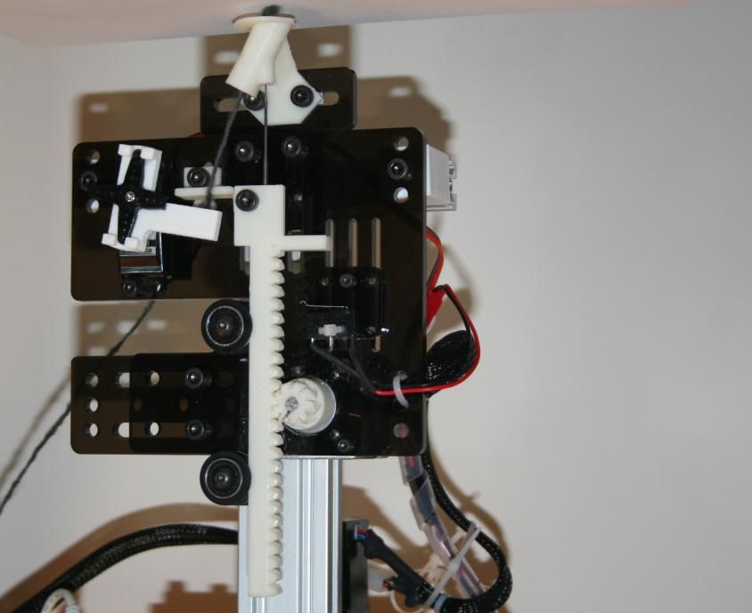
objects are soft and flexible – with a feel and form
somewhat analogous to hand knitted or crocheted objects.
This material moves away from an aesthetic of very precise
shapes and hard lines, towards the more varied texture and
feel of hand crafted fiber arts. However, at the same time        Figure 2. The felting needle used in this work is triangular
we retain the ability to create designs using solid modeling       with barbs in the form of notches placed approximately
software and fabricate them on demand, which is central to                       2mm apart around the needle.
the advantages of additive manufacturing. This opens up           mechanics of control and manipulation of soft bodies as
new possibilities in the creation of interactive objects which    well as the details of sensing in this domain. Soft sensors in
are soft and flexible, and so more suitable to be worn or         particular are of considerable interest for HCI (see for
simply “held close”. Figure 1, shows one such example in          example [16, 19]). These developments all form important
the form of a printed Teddy Bear.                                 prerequisites for progress in this area.
In the next section we will very briefly consider related         CONSTRUCTION OF A FELTING PRINTER
work. We will then consider the details of how our                Felt is a textile which is created by entangling and
prototype printer is constructed and used. Then we will           compressing sheets of fibers (rather than weaving them).
explore several techniques for going beyond creating of           The printing technique introduced in this paper involves a
simple soft solid forms, considering how hard objects (such       process of needle felting where a barbed needle (see Figure
as electronics) might be embedded inside prints, how the          2) is repeatedly passed through a body of fibers in order to
connection between hard and soft materials can be                 draw fibers down into layers below and entangle them
managed, and how we might systematically manipulate the           there. Barbed needles are used for this purpose in the
stiffness of objects. The design and construction of an           commercial manufacture of felt (which is normally done in
example object using these techniques will be considered,         a wet environment such as soapy water, which we do not
then limitations and prospects for future will be discussed.      use) as well as the craft of needle felting. Needle felting
                                                                  craft objects include fibrous decorative materials such as
RELATED WORK
                                                                  felt, yarn, and loose fiber roving, joined onto (i.e.,
Substantial prior work has been done on embedding
                                                                  entangled over and through) loosely woven or knitted
electronics in fabric and fabric-based objects (most notably
                                                                  clothing (such as a sweater). In a more closely related, but
clothing). This has in turn been an enabler for new types of
                                                                  less structured form, needle felting can also used to
interactive devices and new styles of interaction. We will
                                                                  construct full 3D forms from fiber (see for example:
not attempt to review this large literature here, but can point
                                                                  http://www.stephaniemetz.com/portfoliocurrent.html).
to several important themes and a few exemplars of each.
These include: the development of techniques for creation         In the process introduced here we produce three-
of circuits (and more specifically for creating sensors) on       dimensional felted forms in a layered fashion. Like many
and with fabric [2,10,3,5], examining new applications that       other forms of 3D printing we form solid objects by
are enabled by an ability to work with a soft, flexible, or       creating a series of thin layers of material, each representing
otherwise more “personal” forms for electronic device [1,         a horizontal slice of the final geometry. By working from
12], and the personal and community effects engendered by         the bottom of the object up, and bonding each layer of
extending electronic making into new domains, looking for         material together (in this case by needle felting) a complete
example at the relationship of this work to crafts and the        3D object with fairly arbitrary geometry can be formed.
DIY movement [6,13,10].                                           For each layer in this process we place fiber, in the form of
                                                                  yarn, along a winding 2D path which fills the layer. As we
More generally, new technologies for personal fabrication
                                                                  deposit this yarn along the printing path, we bond it to the
have begun to open up new possibilities for exploring the
                                                                  layers below by repeatedly piercing it with a felting needle
space of interactive devices. Recent work has looked at
                                                                  – dragging down individual fibers from the yarn into the
making use of new materials for 3D printed input and
                                                                  layer(s) below and entangling them there.
output components (see for example [18]), new fabrication
techniques using existing technology (such as the                 To accomplish this process mechanically we use a new
innovative use of laser cutting in [9]), as well as new           custom felting print head (described below; see Figure 3)
classes of fabrication (such as the hybrid manual/automated       attached to a precision 3D motion platform. The motion
techniques introduced in [20]). Work has also considered          platform is driven by stepper motors and control electronics
better systems and tools for supporting existing fabrication      which respond to the same “G-Code” commands used for
processes for prototyping of devices (see e.g., [14,15]).         RepRap 3D printers [7] and very similar to those used by
                                                                  many CNC machines [8]. Specifically the open hardware
Another emerging area of considerable overlap with the
                                                                  Arduino-based RAMPS control and drive electronics (see
work presented here is soft robotics (see recent surveys of
                                                                  http://reprap.org/wiki/RAMPS_1.4) and open source
this very large area in [11, 17]). While some of this work is
                                                                  Repetier firmware (see http://repetier.com) are used
motivated by a desire to more easily interact with people,
                                                                  (unmodified).
much of this work is also concerned with the detailed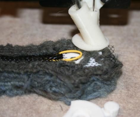
On the (200x200mm) bed of our printer we use a 50mm
thick block of felting foam – a coarse, open pore, foam
Rack rubber which absorbs needle punches well without
degradation. This is topped by a sheet of manufactured felt
Stepper Motor
(behind plate)
which provides a body of “starter fiber” for the first printed
layer to entangle with. The final print may be carefully
peeled away from this base felt, or it may be cut to shape
Pinion and left in place for added strength. The resulting prints are
soft and flexible. They feel somewhat like hand-knitted
material, but in 3D solid, rather than flat form
Servo Motor
Print Head Details
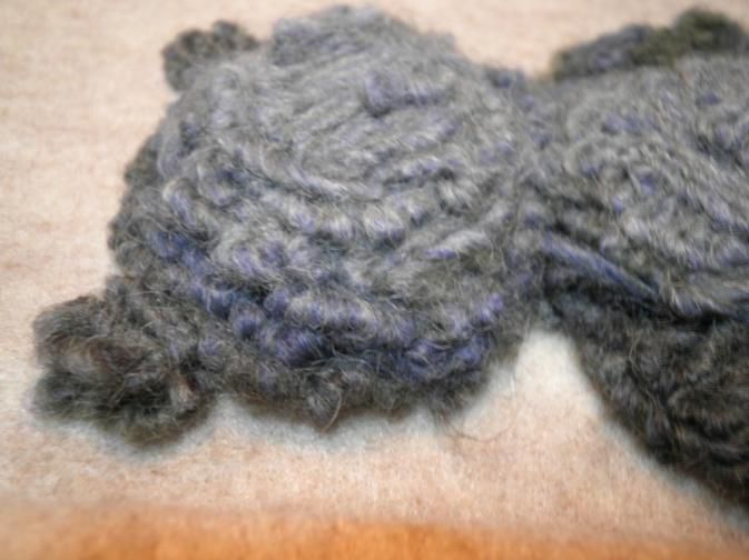
Endstop Figure 3 shows the felting print head which is the heart of
Switch the printer described here. The primary action of the print
head is to drive a felting needle up and down through the
incoming yarn and into the base of previously printed
fibers. This reciprocal motion is provided by a rack and
pinion driven by a stepper motor. A double helical (or
Feed Lock herringbone) gear tooth pattern is used to reduce alignment
Mechanism Felting issues and allow wider construction tolerances, and an
Needle endstop switch is used to establish a home position for the
Yarn Feed
Head rack. The felting needle is attached to the end of the rack
and moves up and down within a custom 3D printed feed
Figure 3. Needle Felting Print Head. The dark mounting head whose interior geometry is shown in Figure 4. This
plate is laser cut acrylic, while white parts are 3D-printed feed head allows new yarn to enter along the tube angled to
This process of forming layers, each constructed from the left. The yarn then joins a 2mm diameter tube guiding
material deposited along a path to fill the layer, is tightly the needle and is contained there with the needle for a
analogous to the process used for Fused Deposition length of 8mm until it emerges through a hole in the center
Modeling (FDM) [4] which is the most common process of the foot. This area where yarn and needle are together in
used for lower-end 3D printing today. (In that process a tightly confined space helps ensure that the barbs on the
melted thermoplastic is extruded from a nozzle in a thin line needle catch some part of the yarn on their trip down.
along a path which fills the layer. The plastic adheres to the To regulate the entry of yarn into the feed head a feed lock
layer below as it cools forming a solid object.) In fact, the mechanism controlled by a servo motor is used. This
process is so similar that we were able to simply attach our mechanism either allows yarn to travel freely from a low
custom print head to an existing FDM printer (initially next friction spool (behind and above the print head) or stops the
to the plastic extrusion head, which we also used to feed of yarn entirely by pinching it between two gripping
separately 3D print some of the parts forming the early bars. This mechanism serves a purpose somewhat
prototype) and directly employ an existing open source analogous to tension control in a conventional sewing
slicing and path planning program for FDM printing machine in that it allows an appropriate amount of yarn to
(Slic3r, see http://slic3r.org), augmented with custom enter the machine for each step along a printing path.
translation software as a post-processor, to drive it. However, conventional uniform tension was found not to
work in this case. Our experimentation with early versions
of the printer showed that a very low friction feed of yarn is
Needle Path Needle critical while the head is in motion between steps, and for
Guide
Tube
the first needle punch of a printing step. This is because
Yarn Feed even small amounts of tension on the yarn feed will create a
Tube tendency for the previous felting location to “pull out”
rather than feeding new yarn in (this is in contrast to
conventional sewing where this pull serves to tighten a knot
in the stitch). On the other hand, the yarn must not feed
Shared
continuously, as each of the multiple needle punches
“Yarn Catch” necessary to properly felt the yarn into the layer below
Section would pull in new yarn. Our experimentation showed that
} this creates felting paths which “bunch up”, rather than
producing a single smooth line of material.
Figure 4. Cut-Away View of Yarn Feed Head.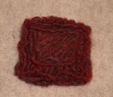
Tensioning which varies during the felting process is             before long moves with a prompt to manually cut the yarn.
accomplished by opening the feed lock before the printer is       We intend to introduce an automatic cutter based on servo
moved to the next step location, and closing it after the first   actuated scissor blades in our next round of prototype
punch of the needle, leaving it closed for the remaining          development.
punches which serve to “felt in” the yarn at that spot. In
                                                                  Material and Printing Details
addition, we regulate the amount of yarn drawn in by the          Needle felting most typically uses unspun fibers (roving)
first punch by making it a bit shorter than later punches         rather than yarn because the spinning process makes the
(pushing the first needle barb 6mm below the foot as              fibers slightly less available for entanglement (they are
opposed to 10mm for later punches).                               already partially entangled with other fibers in the strand).
The printing paths produced from a 3D model by the slicing        However, yarn has the significant advantage that it can be
software are made up of a series of “G-Code” commands             easily spooled and fed through the printing mechanism in a
for linear movements (originally targeting a conventional         controlled and consistent fashion. Nonetheless it may be
FDM 3D printer), some of which also contain commands              useful in future work to consider mechanisms which can
for extruding plastic, and some of which do not. We use a         handle pencil roving rather than yarn.
custom program to translate these commands into modified          Yarn used for the printer must be suitable for felting. Yarn
G-Codes appropriate to drive our machine. In particular,          made from animal hair, most notably wool, is the most
non-extruding moves (and other commands) are tracked,             suitable material due to the micro-structure of its fiber
but passed on to the movement controller as is, while each        surfaces. However we have also had good success with
extruding linear moves are translated into a series of felting    wool blends which include at least 50% wool. Synthetic
steps. We use a step size as close to our target step size        yarns not blended with wool (such as acrylic) appear to be
(currently 2mm) as possible and still produce an integral         unsuitable for felting because the very smooth micro-
number of steps per line. At each step we do the following:       surfaces of the fibers do not entangle well. We also found
1.   Move to the step location                                    cotton fibers to be wholly unsuitable and “superwash” wool
2.   Initiate the punch sequence with control line pulse          (which has been treated to improve washablity) does not
     Performed by independent print head controller:              perform well. Overall we found that less tightly spun yarns
     2.1. Perform an initial (short) needle punch                 with a lot of loose fibers – what might be described simply
     2.2. Close the feed lock                                     as “fuzzy” – produced the best results. However, the
     2.3. Perform N (currently 3) full length felting punches     difference between the best and worst results for a
     2.4. Open the feed lock                                      particular fiber type were not found to be as dramatic as
3.   Wait for the punch sequence to complete                      differences in fiber type – specifically all (non
                                                                  “superwash”) wool and most wool blend yarn we tried
Parts 1,2, and 3 are performed by the unmodified control          felted quite well.
board (and firmware) of the original 3D printer. While
parts 2.1-2.4 are performed by custom drive electronics           Because yarn is soft, inherently variable, and is compressed
(and firmware) for the print head when triggered by a pulse       during printing, accurately measuring of the diameter of
on a control line connecting the two controllers. (The            yarn to establish the proper thickness of layers is a bit
Repetier firmware we used provides G-code commands for            difficult. Most of the yarn we experimented with was
setting the state of unused I/O pins on underlying the            approximately 2mm in diameter (as measured by calipers)
Arduino compatible micro-controller it runs on, so this           and because printed layers are easily compressed this
pulse can be initiated through G-Codes alone without              “round number” worked well for most prints. However, for
modification to the original printer firmware.)                   tall prints (over about 50mm) sub-millimeter inaccuracy in
                                                                  the layer height is compounded. We found it was necessary
As currently configured, a punch sequence takes just under        to empirically determine the best layer height for these tall
1 second (including 100msec to open or close the feed lock        prints. For example we determined that the yarn we used
and 195msec for each full length punch). Moves between            most often printed best in tall prints using a layer height of
felting steps can be performed quickly, resulting in a            2.25mm instead of the 2mm.
printing rate of approximately 2mm per second.
                                                                  Due to the comparatively large thickness of the material
One important limitation of the current prototype print head      being depositing (e.g., 2mm in comparison to 0.5-0.2mm or
is that it does not have a mechanism for cutting the yarn.        less for FDM printing) dimensional accuracy is inherently
Feeding extra yarn during non-felting moves often just            more limited than in other forms of 3D printing. In addition
requires a bit of additional “clean up” after printing (most      to this inherent limitation we also found that the flexibility
extra yarn ends up interior to the object and is just invisibly   and compressibility of the material also contributed to
felted over). However, in some cases previously felted yarn       inaccuracies in the result. For example, we found most
can be “pulled up” during a long move. So to temporarily          prints tended to push ~2-4mm outward from the nominal
compensate for this missing feature of our prototype, our G-      edge of the specified geometric model due to the felting
Code translation software can optionally insert pauses            process in layers above somewhat “squashing” the layers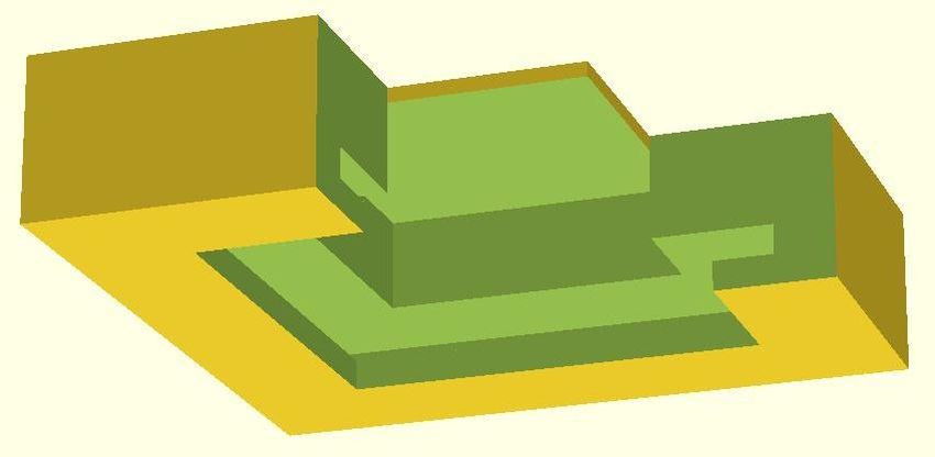
below. Further, this type of effect does not occur evenly.       the model in places where the print head moved from place
This results in an overall randomness of the result which        to place without felting down the yarn. Many of these will
makes its character much more like hand knitting and much        occur inside the solid model. However, the remainder can
less like tightly woven manufactured cloth (or even              be easily removed with scissors.           In addition, the
manufactured felt). While this change of character can be        imprecision of the printing process (partially resulting from
seen as one of the interesting and desirable properties of the   lower layers in some cases being “squashed” or pushed
result, it also limits the feature size of things that can be    aside somewhat by layers above them) can sometime leave
printed with this material. For example, the solid model for     the outside perimeters of layers with small loops or bulges.
the test bear shown in Figure 1 contains features for a small    If desired, these can be “tidied up” by trimming with
nose and eyes (8mm and 4mm wide respectively).                   scissors and/or a bit of hand needle felting work to bind
However, these end up fairly indistinct in the final result.     stray yarn more tightly back into the body of the print.
                                                                 Note that these cleanup steps are very much analogous to
Due to the flexibility of the material we were initially
                                                                 the kind of trimming and sanding work that is very often
concerned that we would be unable to print taller objects.
                                                                 needed to clean up FDM printed plastic models on typical
However, in our tests we found that we could successfully
                                                                 lower-end printers.
print objects up to the limit of our initial prototype machine
(75mm tall) as long as they were not too narrow. For             In addition to cleanup steps it is also possible to increase
example we printed a 50mm diam x 75mm tall cylinder              the tightness of fiber binding within the resulting felt and
without much difficulty (once an accurate layer height was       the overall density of printed objects by agitating the
determined). However, for a similar 30mm cylinder we             objects in hot water (typically along with a surfactant such
encountered some distortions at higher layers from the           as mild soap). Our experiments show that this makes the
“wobble”, and large problems for a 20mm cylinder.                resulting objects considerably firmer. However, the wool
                                                                 fibers making up the object also shrink changing the
As in several other types of 3D printing, the geometry of
                                                                 dimensions of the object.              Considerably more
printed objects cannot be completely arbitrary.            In
                                                                 experimentation is needed to properly characterize these
particular, geometry containing overhangs, where part of a
                                                                 effects and of course this post-processing may be
layer has little or no material in the layer below it, can be
                                                                 problematical if embedded electronics are used.
problematical since at the limit the layer can be “printing
over thin air”. This same limitation applies to e.g., FDM        FUNCTIONAL AND STRUCTURAL COMPONENTS
printing. For FDM printing this can be overcome by               Printing of custom solid soft objects provides an interesting
printing extra sacrificial support material which is removed     new capability in and of itself. However, to take full
in a post-processing step. Even without support material,        advantage of this capability for innovative interactive
overhangs of up to 45° can typically be supported (45° is        devices, we would like to integrate additional electronic and
the theoretical tipping point at which the center of gravity     mechanical components and may also want to manipulate
of an overhanging flat object is outside the profile of an       the structural properties of the resulting object. In this
identical object below it). In fact in FDM printing              section we consider some of these aspects. Considerable e-
overhangs of a bit more than 45° can sometimes be printed        textiles work has been done which shows e.g., how to
without support due the adhesion of the material when it is      integrate electronic components with fabric objects. Much
hot.                                                             of this work is applicable in this domain as well and can
                                                                 largely be reused. Consequently, we will not cover it in
While the felting printer can also print extra material to       detail here. For example, it should be easy to stitch in areas
provide support for overhanging elements of the geometry,        of conductive thread to create capacitive touch sensors [5].
it can be a tricky to determine exactly what material should     In this section, we will instead concentrate more on aspects
be removed and remove it without damage to the layers            which are mostly unique to the nature of this work such as
above. To determine how much overhang can be tolerated           its 3D form.
without support, we performed tests on objects with
increasing overhang angles. We found that as the overhang        Cavities and Embedding
increased deeper layers would get pushed out farther from        To explore the full potential of soft printed objects as a
their intended locations resulting in a gradual degradation      form factor for interactive devices we would like to embed
of the shape away from its intended geometry. However,           electronic components for sensing and display, as well as
this gradual degradation also allowed overhang angles up to      motors and mechanisms for actuation within the material.
55° in our tests to print without failure (which usually         Unfortunately, many of the components we might like to
manifests itself as a tangle of unfelted yarn).                  embed would not seem to be very compatible with repeated
                                                                 strikes from a very sharp motor-driven needle. For
Post-Processing                                                  example, it would seem a normal printed circuit board
After printing is complete a number of post-processing           would likely bend or break the needle (or at least forcibly
steps may be performed. The first of these is a set of           alter its z-position and ruin subsequent felting punches),
cleanup steps. Since our prototype printer does not yet          while the needle might puncture and damage softer
contain a yarn cutter, extra lengths of yarn will be left with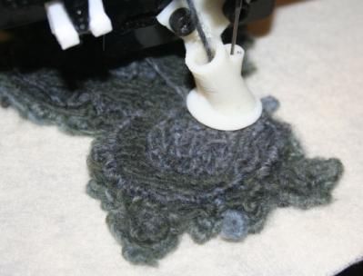
components such as typical flexible circuit materials and         option. For these cases we can consider several other
some conductors.                                                  approaches.
To address this challenge we have developed several               First, based on our experiments we have determined that it
different embedding mechanisms which can be used in               is possible to simply felt over a few more types of objects
different circumstances. In this section we consider five         than is immediately apparent. For thin wires (stranded
methods: Sew in/on later, Deep pocket embedding, Direct           insulated wire, solid insulated or bare wire, as well as
felt-over, Capped pockets, and Nylon braid tunnels.               typical through-hole component leads up to approximately
                                                                  1mm in diameter) our experiments show that they can be
The simplest solution, and one used by most previous
                                                                  simply placed on top of a layer in a paused print, held
fabric-based devices, is to simply sew components onto or
                                                                  loosely in place by hand or with pins, and simply felted
into the body of the felted object after it has been
                                                                  over. Our observations show that when the thin needle
constructed.    For example circuit boards and other
                                                                  strikes these objects they simply shift slightly to one side to
components can be sewn on the outside of the object, or
                                                                  allow it to pass (although in a few cases the needle bent the
under a sewn on flap. Also because the material is soft and
                                                                  wire slightly rather than simply shifting it). Similar results
fibrous, a sewing or yarn needle can be used to pull
                                                                  were also obtained with conductive thread. We did not see
conductive thread through a considerable depth of material
                                                                  thread breakage in our tests. We also have not observed
(limited only by the length of the needle), or from the
                                                                  spurious conductivity between felted in conductive threads
surface of the material to an interior cavity (see below).
                                                                  crossing at right angles and separated by a layer of felted
This would allow, for example, components such as LEDs
                                                                  yarn. However, we do not feel our tests at present are
sewn onto the surface, to be easily connected to interior
                                                                  exhaustive enough to determine that this will always avoid
components such as a micro-controller. In fact, due to the
                                                                  shorts.
pioneering fabric-based interface work of the past, a range
of electronic components specifically designed for sew on         In a “torture test” we also successfully felted over a 2.5mm
use are currently available commercially (see for example         wide nylon wire tie. In this case the needle hit the wire tie
the over 100 E-Textile products listed for sale at:               on every pass across it and was unable to shift it out of the
https://www.sparkfun.com/categories/204).                         way in most cases. However, due to the flexibility of the
                                                                  wire tie itself and the compressibility of the 50mm foam
Since both the exterior and interior geometry of an object
                                                                  pad on the bed of the printer, the material was depressed
can be fairly arbitrary, it is also possible to create interior
                                                                  enough to avoid breaking the needle or causing its motor to
cavities or pockets to hold components.             With this
                                                                  skip steps, and the print continued successfully. This
approach, an interior void is specified in the object
                                                                  indicates that the direct felt-over approach may be more
geometry. When the print reaches some number of layers
                                                                  viable than immediately obvious. However, more testing is
past the bottom of this void, it can be paused. Then a
                                                                  needed to define the range of its applicability.
component can be placed in the partial or complete pocket,
and the print continued, forming layers over the top of the       For cases where direct felting-over is not viable, we have
pocket.                                                           developed a more involved capped pocket method which
                                                                  allows objects to be placed in pockets no deeper than the
However, the nature of the printing process constrains this
                                                                  embedded object so long as the pocket can be placed within
approach. In particular, to create good felted bonds
                                                                  a few printing layers of the top of the print (or an
between layers our experimentation has shown that the
                                                                  indentation at the top of the print is acceptable). To do this,
felting needle should generally penetrate 15mm into the
                                                                  we first separately print a thin cap consisting of a felt base
material (this includes 5mm of needle which has no barbs
                                                                  with one or two layers of yarn felted on top of it. The felt is
and approximately 5 barbs on the next 10mm of the needle
                                                                  cut with a ~4mm “lip” sticking out past the printed yarn
shaft). This means that for hard or vulnerable components
                                                                  layers. In the main object we use a pocket geometry
(such as printed circuit boards) there must be a 15mm gap
                                                                  illustrated in the cutaway view of Figure 5 (top). The print
between the top of the component and the top of the pocket.
                                                                  is stopped one layer above the top of the pocket, the
Since we generally cannot “print in mid-air” over large
                                                                  embedded object is inserted, the previously printed cap
unsupported areas, we accomplish this by placing a small
                                                                  (with its felt base) is placed on top, and the print is
piece of foam or other “stuffing material” (such as polyester
                                                                  continued. The remaining layers then felt through the cap
fibers or even simply yarn) in the 15mm void above the
                                                                  lip and abut the cap yarn layers. This results in a surface
embedded component. Printed layers at the top of the deep
                                                                  covered with felted yarn as shown at the bottom of Figure
pocket then felt into this support material and the needle
                                                                  5, but is formed in a way which never has the needle
does not strike the embedded component.
                                                                  intrude into the embedded object’s pocket.
This deep pocket approach to embedding is suitable for
                                                                  A final method for embedding objects can be used if small
large prints which can contain a ~20mm tall interior void.
                                                                  embeddings away from the print surface are needed and
However, for thin objects this is unlikely to be a viable
                                                                  objects can be inserted from the side after printing, or when
                                                                  long passages are needed (e.g., for multiple wires or even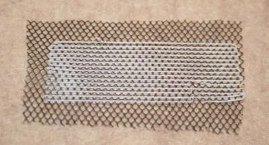
Cap felt “lip” placed here   In order to address this issue and provide more usefulness
                                                                    for resulting printed objects we have developed a simple
                                                                    technique for bridging between hard and soft materials.
                                                                    This technique involves felting in a layer of nylon mesh
                                                                    fabric to form this interface. The holes in the mesh allow
                                                                    felting fibers to pass through it and be entangled in layers
                                                                    below the mesh. This thoroughly embeds the mesh within
                                                                    the felting and can be done without otherwise disturbing the
                                             Print paused at this   print (as with other embedding, fibers of the mesh appear to
                                              layer for object &    shift slightly when they happen to be struck by the thin
                           Object pocket
                                                cap insertion       felting needle). Since the mesh stretches slightly (but less
                                                                    than the felting) this allows any forces on the mesh to be
                                                                    distributed over the whole area where it is embedded.
                                                                    Specifically lateral forces on the mesh will be transferred to
                                                                    the fibers of the felting at the boundary of nearly every hole
                                                                    in the mesh rather than being concentrated in a small area,
                                                                    e.g., immediately around a hard connection point.
                                                                    This leaves the problem of attaching hard objects to the
                                                                    nylon mesh. The nylon mesh is much stronger than the
                                                                    printed felt and in many cases is sufficiently strong to attach
                                                                    to directly. However, to provide more robustness for
                                                                    attachment and allow us to also spread out the forces
 Figure 5. Cutaway view of capped pocket internal geometry          applied from a hard object into the mesh, we have
            (top), and resulting cap surface (bottom).              developed a double embedding technique.
thick cables). This method makes use of flexible nylon              This technique embeds the mesh within the plastic of a 3D
braided tubes which are sold for use as wire bundle covers.         print (created with an FDM 3D printer, in our case printing
In this case, the print is paused, and the nylon tube is placed     PLA plastic). Figure 6 (right) shows an example of this.
on top, then loosely pinned or held in place. The print then        Here we have constructed a large grommet around a 5mm
continues, felting the tube in place through the braid, first       mounting hole which is embedded in a patch of nylon
with one layer only at the edges, then fully over the tube          mesh.
(see Figure 7). After printing is complete, the interior of
the tube can be partially cleared of fibers with e.g., a small      To construct this embedding we create a solid model for the
screwdriver shaft, and then objects may be inserted into the        grommet which leaves a small (1 layer) gap for the mesh.
relatively slippery nylon tube. To accommodate thicker              The layers below the mesh are printed. The print is then
objects the layers above and below the tube can be                  paused and the mesh taped in place over the partially
constructed with small gaps or holes to allow more room             constructed grommet. The print is then resumed (with the
for the tube to expand (and partially displace those layers).       printer having skipped the layer containing the mesh as
Figure 8 shows the use of this type of nylon braid tunnel as        specified in the solid model) to print layers of plastic over
part of a flexible bend actuator.                                   the mesh. This results in an embedded patch of mesh which
                                                                    is tightly bound to the plastic layers surrounding it. A mesh
Bridging Between Hard and Soft Materials
                                                                    patch prepared in this way can then be felted into an object
In order to fasten printed objects to most types of materials
                                                                    printed on the felting printer using one of the embedding
it is necessary to bridge between hard “external” materials
                                                                    techniques described in the last subsection.
(or fasteners) and the soft felted material produced by the
printer. Such a bridging is also necessary if internal motors       For our experiments with this technique we used a nylon
or other actuators are to be embedded in the object to move         mesh with ~2mm holes which appears very suitable for
it, since the solid actuator must push or pull the felting.         embedding both in the FDM deposited plastic and the
Unfortunately, the felting which results from the printer is        felting. The mesh is ~0.2mm thick. However, to provide
not as strong as e.g., typical fabric. In addition, we do not       clearance for potential unevenness in the mesh and/or very
necessarily have the ability to apply reinforcement                 small wrinkles we used a 0.4mm layer height in the FDM
techniques developed in that domain such as the extra               print (hence leaving a 0.4mm gap for the mesh). When
stitching around button holes. As a result, when forces end         initially deposited, the hot thermoplastic seems to flow over
up being transferred from e.g., an attachment point with a          and through the mesh, including any small irregularities,
bolt, rivet, or other solid connector, into the printed object,     and bonds firmly with the plastic in the layer below. We
it is often not (at least in the long run) strong enough, and       found that two plastic layers below and two plastic layers
will tend to (eventually) rip out.                                  above the mesh were quite sufficient to create a solid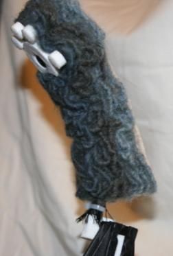
However, we found that this sort of fabric stiffener could
                                                                    only increase stiffness to a low to moderate degree. To
                                                                    achieve more stiffness (and make it easier to place and
                                                                    tailor stiffness at modeling time) we also experimented with
                                                                    the creation of custom stiffening sheets. In this technique
                                                                    we again used nylon mesh embedded in 3D printed plastic.

Figure 6. (Left) Nylon mesh interface layer embedded in a 3D        In this case we printed a series of thin lines bonded above
  printed hard plastic grommet (with 5mm mounting hole).            and below the mesh as shown in Figure 6 (right). This
The nylon mesh can then later be embedded in a felting print        material is constructed from a solid model with the same
   to provide a smooth distribution of forces applied to the        mesh embedding procedure described above. These lines
  grommet across the many fibers felted through the mesh.           were designed to be narrow enough (and widely spaced
         (Right) Custom 3D printed stiffening sheet.                enough) that they could be easily felted over – like other
                                                                    narrow objects we tried, the lines appear to shift slightly
   mounting, but thicker and more varied geometries could be        rather than break if they happen to be struck by the needle.
   used.                                                            Sheets of this type can then be felted into the body of a
  This technique is particularly flexible because the solid         print to significantly increase stiffness where desired. Like
  model for the plastic part of the interface can be specified to   the hard/soft material interface described above, the use of
  directly mate with the mounting holes and/or other                an embedded mesh allows forces to be distributed across an
  geometry of the specific part being attached or embedded.         area, making the presence of a stiff material inside a soft
  We also have flexibility in how much mesh surface is used         one less problematic. Because the stiffeners are 3D printed,
  to absorb and distribute forces and can tailor that surface       the exact placement of stiff versus flexible regions can be
  area in the direction(s) we expect forces from the hard/soft      easily specified as part of the solid model for the stiffening
  interface to be applied from.                                     plastic. Further the exact stiffness can be varied by leaving
                                                                    alternating gaps in the lines and/or manipulating the space
  Manipulating Stiffness
                                                                    between them. This allows us to very finely manipulate the
  A final area we explored was manipulating the stiffness of
                                                                    details of stiffness properties and thus to create objects
  printed objects. This is useful for example, for creating         which can be highly tailored to their intended use. For
  joints within articulated characters or foldable devices.         example objects on the outside of clothing can be made to
  There we would like the joint to be more flexible than the        bend where they need to for comfort, while being more
  material adjacent to it so that bending occurs at the joint       ridged in other locations.
  rather than elsewhere.
                                                                    For our experiments with custom stiffeners we used the
  For this purpose we looked at three techniques. First we
                                                                    same nylon mesh as our hard/soft material interfaces. Like
  can increase the flexibility of the resulting printed object by   those tests we used two 0.4mm layers below the mesh, a
  leaving small gaps in the geometric model used to create it.      0.4mm gap for the mesh itself and two layers above the
  This causes the creation of small voids which bends can           mesh. We deposited the thinnest lines available on the
  collapse into.                                                    printer (~0.4mm wide).
  To increase stiffness we looked at two techniques. In the         As is evident in Figure 6 (right), the resulting print typically
  first we placed a layer of low stretch fabric within the print.
                                                                    contained some flaws. These were caused in two ways.
  This fabric was felted into the body of the print, with fibers    First the very narrow lines did not respond to unevenness in
  from the layer above the fabric passing through it to felt        the mesh well in a few places. In particular, the extruded
  with the layer below.                                             plastic bead did not have plastic next to it which would help
  In our experiments we used a thin nylon organza fabric –          to hold it closer to its intended position when irregularities
  essentially a very thin woven nylon mesh. The properties          occurred. Second, the very narrow separated lines stuck
  of this particular fabric cause it to be both amenable to         nearly as well to the printer bed as to the mesh and layer
  felting fibers through, and exhibit low stretch. However,         above, and so in a few spots the layers delaminated when
  many other fabrics could likely be used for this purpose.         they were removed from the printer. Also, although
                                                                    inconclusive, our experiments raised questions about the
  Since the fabric was less stretchable than the felt that was      long term robustness of the printed stiffeners – whether the
  formed through it, it resisted bending somewhat more than         thin lines might break over time and hence decrease
  the surrounding felt, thus somewhat increasing the stiffness      stiffness. Our tests were done with PLA thermoplastic.
  of the area it was embedded in. Additional layers of non-         However, it is likely that nylon would be a more robust
  stretch fabric can be embedded to increase stiffness. This        material to deposit for this purpose.
  allows us to create a range of different stiffnesses to meet
  different needs. It also allows the stiffness of an object to     EXAMPLE USE
  shift incrementally across an area rather than changing at a      As an illustration of how the techniques described above
  single point from most to least stiff.                            can be brought together to create functional interactive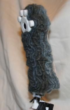
or
                                  yf
                               Bod d Paw
                           ted an
                      Pri n rm ,
                  l t        A
               Fe lder,
                  o  u
               Sh
                                                             ,&     Stif
                                                      l b ow            fen
                                                    E       s                 e rs
                                               e r, i n t
                                        o u l d i st Jo                         Embedded
                                      Sh Wr                                    Paw & Tendon
                                                                                 Connector
                                                                        ed
       Servo Mounting                                                int
                                                                   Pr arts
      Bracket & Tendon                                         M       P
       Tube Connector                                        FD stic                             Figure 8. Partially printed arm example showing
                                                              Pl a
                                                                                                    embedded components. Here we can see an
                                                                                                   embedded black nylon mesh tube (left) which
 Figure 7. Exploded view of a geometric model for articulated arm example.                          holds a yellow tendon wire. This wire loops
  The shape at the top left is printed on the felting printer, while the shapes                  around a bolt which attaches the (white) assembly
   along the lower right are 3D printed plastic parts, several of which are                       under it that is being printed over at this point.
     designed to include embedded nylon mesh. These plastic parts are                             This assembly contains an embedded metal nut,
   embedded inside of, or attached to, the felt component to form the final                      nylon mesh to spread forces from the hard attach
 functioning arm which bends smoothly at shoulder, elbow, and wrist joints.                          point and 3D printed stiffening material.
objects, this section describes the design and construction                          components and some assembly by hand placement of
of a partial prototype for an articulated soft object. In                            embedded objects (and attachment of a bolt), each of these
particular we consider an internally articulated arm which                           parts can be specified and manipulated in a purely virtual
could be part of an interactive teddy bear. This example                             solid model and can be printed on demand. This allows for
combines embedding, hard/soft bridging and stiffness                                 very rapid exploration of a space of prototypes which
manipulation to create a soft arm which bends smoothly                               would not be possible without the use of this technology.
under control of a servo motor (which could in term be
                                                                                     LIMITATIONS, CONCLUSION AND FUTURE WORK
driven from an embedded microcontroller which could e.g.,                            This paper has demonstrated the basic capability to 3D print
capacitively sense touch using conductive thread). Figure 7                          objects in a soft material composed of needle felted yarn.
shows the solid model which was used to print each of the                            This new material opens up many new possibilities for 3D
parts making up the final object which is depicted in Figure                         printed objects and extends the domain of 3D printing from
9. The form in the upper left of Figure 7 is the felted                              primarily hard and precise objects into a domain which can
portion of the print which was printed on the felting printer.                       include soft and imprecise objects. This allows the
The parts arrayed on the lower right are printed on an FDM                           exploration of a very different design aesthetic while still
3D printer. Several of these parts are designed to be                                allows the many advantages of additive manufacturing
embedded over nylon mesh as described in the last sections.                          techniques. These include the ability to rapidly move from
These parts include: a mounting bracket which connects a                             ideas, through virtual geometric models, to physically
servo motor to a polyethylene tube which in turn connects                            realized forms. In this case we are able to design objects
to a nylon braid tube (not shown); stiffening elements with                          with mature solid modeling tools, and then print these
gaps to support bending preferentially at shoulder, elbow                            objects in a few hours. This can be contrasted with roughly
and wrist joints; and an embedded connector (with                                    equivalent hand knitted objects which do not have similar
embedded metal nut (not shown)) which attaches a tendon                              design tools (at least with respect to their 3D
wire to the paw plate with a small bolt (not shown). The                             characteristics) and would take days to create.
tendon wire runs from the servo motor to a solid attachment
point under the paw plate. When this wire is retracted the
arm bends (up) at the shoulder, elbow, and wrist joints
formed by gaps in the stiffener as well as voids in the felt.
The full assembly arrayed in the lower right of Figure 7 is
embedded inside (or attached to) the felt shown at the upper
left as it is printed. Figure 8 shows some of this embedding
part way through the printing process, while Figure 9 shows
the final result.
This example illustrates some of the range of structures
which might be combined to create fully interactive soft
devices.   Although this example requires multiple
                                                                                                     Figure 9. Final printed arm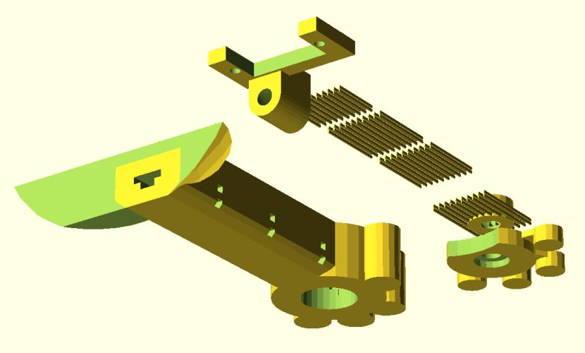
However, the work presented here is only a beginning. The             Report (NISTIR) – 6556. Available from:
printing technique described here has several limitations             http://www.nist.gov/ manuscript-publication-
and considerable future work is still needed. Perhaps the             search.cfm?pub_id=823374
most important limitation of this technique is the physical       9. Mueller, S., Kruck, B., and Baudisch, P. (2013)
robustness of the resulting felted objects. These objects             “LaserOrigami: laser-cutting 3D objects”, In Proc. of
exhibit reasonable strength for forces applied laterally to           the SIGCHI Conf. on Human Factors in Computing
layers.     However, they are less robust to forces                   Systems (CHI '13), pp. 2585-2592.
perpendicular to layers, tending to pull the layers apart. To     10. Perner-Wilson, H. and Buechley, L. (2010) “Making
improve robustness in that direction in future work we may            textile sensors from scratch. In Proc. of the
consider injecting very small amounts of a flexible adhesive          International Conf. on Tangible, Embedded, and
in conjunction with the felting process in order to more              Embodied Interaction (TEI ’10), pp. 349-352.
permanently bind felted fibers between layers. However,           11. Pfeifer, R., Lungarella, M., and Iida, F. (2012) “The
considerable experimentation will be needed to find an                challenges ahead for bio-inspired 'soft' robotics”.
appropriate adhesive and application process. In particular,          Commun. ACM 55, 11, pp. 76-87.
a balance will need to be struck between adhesion and             12. Rosner, D., and Ryokai, K. (2008) “Spyn: augmenting
resulting stiffness if the soft character of the results are to       knitting to support storytelling and reflection”, In Proc.
be maintained.                                                        of the International Conf. on Ubiquitous Computing,
                                                                      pp.340-349
Although imprecision is in some sense a desired part of our
                                                                  13. Rosner , D., and Ryokai, K., (2009) “Reflections on
result, another limitation of the technique is that it may be
                                                                      craft: probing the creative process of everyday knitters”,
too imprecise for some uses.          Finally, we feel that
                                                                      In Proc. of the ACM Conf. on Creativity and Cognition,
considerably more exploration is needed in designing new
                                                                      pp. 195-204.
types of mechanisms, structures, and electronic sensors,
                                                                  14. Saakes, D., Cambazard, T., Mitani, J., and Igarashi, T.
within, around, and with this new material.
                                                                      (2013) “PacCAM: material capture and interactive 2D
REFERENCES                                                            packing for efficient material usage on CNC cutting
1. Berglin, L. (2005) “Spookies: Combining smart                      machines”. In Proc. of the ACM Symposium on User
   materials and information technology in an interactive             Interface Software and Technology (UIST '13), pp. 441-
   toy”, In Proc. of Interactive Design and Children (IDC             446.
   ’05), pp.17-23.                                                15. Savage, V., Zhang, X. and Hartmann, B. (2012)
2. Buechley, L., Eisenberg, M., Catchen, J. and Crockett,             “Midas: fabricating custom capacitive touch sensors to
   A. (2008) “The LilyPad Arduino: Using Computational                prototype interactive objects”, In Proceedings of the
   Textiles to Investigate Engagement, Aesthetics, and                ACM Symposium on User Interface Software and
   Diversity in Computer Science Education”, In Proc. of              Technology, pp. 579-588.
   the SIGCHI on Human factors in Computing Systems               16. Slyper, R., Poupyrev, I., and Hodgins, J. (2010)
   (CHI ’08), pp. 423-432.                                            “Sensing through structure: designing soft silicone
3. K. Cherenack, C. Zysset, T. Kinkeldei, N.                          sensors”, In Proc. of the International Conf. on
   Münzenrieder, and G. Tröster (2010) "Woven Electronic              Tangible, Embedded, and Embodied Interaction (TEI
   Fibers with Sensing and Display Functions for Smart                '11), pp. 213-220.
   Textiles," Advanced Materials, vol. 22, no. 45, pp.            17. Trivedi, D., Rahn, C., Kier,W, and Walker, I (2008)
   5178-5182.                                                         “Soft robotics: Biological inspiration, state of the art,
4. Crump S. (1992) “Apparatus and method for creating                 and future research”, Applied Bionics and
   three-dimensional objects”, US Patent 5121329A.                    Biomechanics, v5, n3, pp. 99-117.
5. Holleis, P., Schmidt, A., Paasovaara, S., Puikkonen, A.,       18. Willis, K., Brockmeyer, E., Hudson, S. and Poupyrev, I.
   and Häkkilä, J., (2008) “Evaluating capacitive touch               (2012) “Printed optics: 3D printing of embedded optical
   input on clothes”, In Proc. of the Conf. on Human                  elements for interactive devices”. In Proc. of the ACM
   Computer Interaction with Mobile Devices and Services,             Symposium on User interface Software and Technology
   pp. 81-91.                                                         (UIST '12), pp. 589-598.
6. Johnson, J. S., Hawley, J. (2004) Technology's impact          19. Yoshikai, T., Fukushima, H., Hayashi, M., and Inaba,
   on creative traditions: Pieceful co-existence in quilting.         M. (2009) “Development of soft stretchable knit sensor
   In Clothing and Textiles Research Journal, 22(1/2), pp.            for humanoids' whole-body tactile sensibility”, In Proc.
   69-78.                                                             of the IEEE-RAS International Conf. on Humanoid
7. Jones, R., Haufe, P., Sells, E., Iravani, P., Olliver, V.,         Robots. pp. 624-631.
   Palmer, C. and Bowyer, A., (2011) “RepRap – the                20. Zoran, A., Shilkrot, R., and Paradiso, J. (2013)
   replicating rapid prototyper”, Robotica, 29, pp. 177-191.          “Human-computer interaction for hybrid carving”. In
8. Kramer, T., Proctor, F., Messina, E. (2000) “The NIST              Proc. of the ACM Symposium on User Interface
   RS274NGC Interpreter - Version 3”, National Institute              Software and Technology (UIST '13) pp. 433-440.
   of Standards and Technology Interagency/Internal
You can also read