Region of Interest Coding for Aerial Video Sequences Using Landscape Models
←
→
Page content transcription
If your browser does not render page correctly, please read the page content below

Provisional chapter
                                                                                                                          Chapter 3

Region of Interest Coding for Aerial Video
Region of Interest Coding for Aerial Video Sequences
Sequences Using Landscape Models
Using Landscape Models

Holger Meuel, Julia Schmidt,
Holger Meuel, Julia Schmidt, Marco Munderloh and
Marco Munderloh and Jörn Ostermann
Jörn Ostermann
Additional
Additionalinformation
           informationis is
                         available at the
                            available     endend
                                      at the  of the chapter
                                                  of the chapter

http://dx.doi.org/10.5772/52904

1. Introduction
Video coding standards traditionally work in a block-based manner wherein every block
basically receives the same treatment. For certain kinds of videos, such as movies for
television, this might indeed be the sensible thing to do.
Depending on the use-case, though, it often is helpful to treat different areas of the image
with different coding parameter sets or techniques even. In applications with focus on
moving objects for example, a better resolution in the identified Regions of Interest (ROI)
might help subsequent processing steps within a larger system. Existing video coding
standards, such as MPEG-1,2,4 video or the ITU-T H.26x standards, only provide basic support
for ROI coding. In e. g. MPEG-4 Video Object Planes (VOPs) and the separate encoding of these
planes is included [1]. Unfortunately these features aren’t used to the extent possible, even
though several real-life applications could be enhanced by such systems. Surveillance and
videoconferencing tasks for example can benefit from a special ROI coding approach, wherein
objects are automatically selected by e. g. motion (surveillance), color [2] (videoconferencing),
shape or have been selected manually beforehand. Those regions are then coded with a
higher quality than the rest of the picture. Especially for narrow-band transmission channels
as used e. g. in aerial surveillance, it is important to keep the amount of data to be transmitted
for the conduct of the task at hand to a minimum. In ROI coding it is one possibility to reduce
this amount of data by degrading the quality of the parts of the image that are not as useful
to the application.
Instead of decreasing the image quality by coarser quantization, it is also possible to code
non-ROI regions in skip-mode. In the case of a static camera this leads to loss of changes and
local motion in those areas. In the case of a moving camera, the lost motion information
might be predicted and compensated, when only linear global movement is taken into
account.

                         ©2012 Meuel et al., licensee InTech. This is an open access chapter distributed under the terms of the Creative
                         Commons Attribution License (http://creativecommons.org/licenses/by/3.0), which permits unrestricted use,
                          © 2012 Meuel
                         distribution, andet al.; licenseein
                                           reproduction    InTech. This is an
                                                             any medium,      open access
                                                                            provided       articlework
                                                                                     the original distributed  under
                                                                                                        is properly    the terms of the Creative
                                                                                                                    cited.
                          Commons Attribution License (http://creativecommons.org/licenses/by/3.0), which permits unrestricted use,
                          distribution, and reproduction in any medium, provided the original work is properly cited.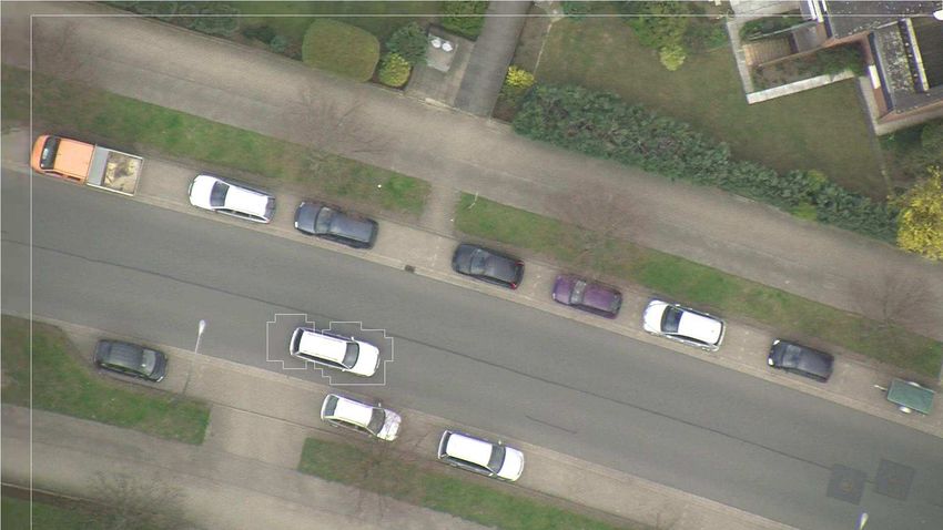
52   Advanced Video Coding for Next-Generation Multimedia Services
2    Video Coding

     In general it is desirable to reconstruct high overall image quality at low data rates. For
     aerial video sequences, which often show predominantly static scenarios and only little
     changes in regions with moving objects, this can be done by allowing certain assumptions.
     One assumption to reduce data rates is the planarity of the landscape recorded. This
     simplification enables projecting the entire scene into one plane and rendering it as one
     big image when using Global Motion Estimation/Compensation (GME/GMC) at encoder side. At
     decoder side this opens the possibility of reconstructing the current image through outtakes
     of this so-called mosaic.
     In existing GME/GMC approaches for aerial surveillance, GME is based on a projective
     transform [3]. To estimate the global motion of a scene, features have to be detected e. g. with
     a Harris Corner Detector [4] first. These features will be tracked from frame to frame e. g. with
     a KLT feature tracker to estimate their movements [5]. Finally, from all trajectories the global
     motion can be estimated based on an affine or projective transform. When transmitting the
     global motion parameters as additional side information, GMC can be applied at decoder side.
     With implementations employing GMC, data can be reduced dramatically for the example
     of aerial surveillance. However, to reconstruct moving objects at the decoder, additional
     data about those has to be transmitted. Consequently the achievable data rate reduction
     strongly depends on the number of moving objects in a scene. For scenes consisting of a
     static background and some moving objects, overall bit rate reductions of about 50 % can be
     easily achieved.
     The true surface of most scenes however isn’t flat at all. This leads to mapping errors during
     the GMC process due to the use of a projective transform. The effect will be more obvious
     for applications with low recording altitudes and scenes containing areas with large height
     differences, such as mountains or buildings. For aerial surveillance this leads to falsely
     detected moving objects and unnecessarily transmitted data when a difference-image-based
     moving object detector is used. For those cases a model that consists of several small planes,
     as it is realized through a mesh-based approach, takes into account the aforementioned
     differences. It prevents partial misregistration due to insufficient GMC of image content by
     better adapting to perceived local motion. The basic idea is that several feature points of
     an aerial video sequence are visible over consecutive frames and can therefore be tracked
     and triangulated into a mesh. All triangles of the mesh are motion compensated by using
     the motion vectors acquired during the tracking process. For motion compensation, only
     piecewise planarity is assumed, which is correct for small mesh patches.
     In scenarios where interesting regions are identified by motion, the mesh approach yields
     several additional advantages and the rate of objects that are falsly classified as moving can
     be reduced by up to 90 % when compared to planar landscape model-based approaches [6].
     This chapter gives a more real-life scenario oriented insight about the usage of different
     techniques for content adaptive video coding. The emphasis will lie on ROI coding and
     decoding for aerial sequences with a detailed view on:

     • Assumption of planar earth surface: Projective transform-based global motion
       compensation and detection of moving objects
     • Approximation of the earth surface using a mesh:                Mesh-based global motion
       compensation and detection of moving objects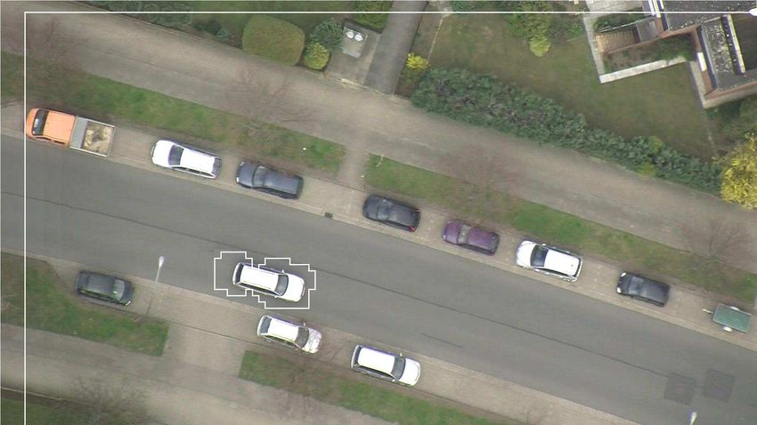
Region of Interest Coding for Aerial Video Sequences Using Landscape Models    53
                                                     Region of Interest Coding for Aerial Video Sequences Using Landscape Models 3
                                                                                                       http://dx.doi.org/10.5772/52904

                                   12
                                                     Mob.Chan.Cap.                     AVC
                                   10                  TV resolution
             Data rate in Mbit/s                     HDTV resolution
                                        SP
                                   8

                                   6                                                                        HEVC

                                   4                ASP                                          AVC+
                                                                                                 GMC+
                                                                                         AVC     ROI
                                   2                                                                        HEVC+
                                                       ASP+ROI                                            GMC+ROI?
                                   0
                                             2000    2002        2004     2006       2008      2010       2012       2014
                                                                            year

Figure 1. Data rates of different video codecs with and without Region of Interest (ROI) coding for aerial video sequences (SP:
MPEG-4 Simple Profile, ASP: MPEG-4 Advanced Simple Profile, AVC: Advanced Video Coding (MPEG-4 part 10/H.264), HEVC:
High Efficiency Video Coding).

1.1. Limits of standard-based coding
In its long tradition back to H.261 [7] from 1988, standardized digital video coding has reached
amazing coding efficiency. Advanced Video Coding (AVC) is able to compress PCM (Pulse Code
Modulation) coded data with a data rate of 166 Mbit/s for SDTV sequences (PAL resolution as
used for DVB: 768 × 576 pel) to about 2–4 Mbit/s at a fairly high subjective quality. HDTV video
with 1920 × 1080 pel can be compressed to about 10–20 Mbit/s depending on the video content.
The latest standard, High Efficiency Video Coding (HEVC), needs only half the bitrate.
If mobile channels like WCDMA/UMTS and LTE are used for transmission, channel capacity
is limited to a few Mbit/s. Especially when looking towards upcoming scenarios such as
video transmission from Unmanned Aerial Vehicles (UAVs), there definitely is a need for a
higher level of compression than offered by standardized coding techniques at the moment.
Municipal agencies have recently started utilizing such UAVs for environmental and disaster
area monitoring, so this use-case is especially important to work on. It has to be noted that
in real-life scenarios other basic requirements, besides from what is known from television
signal transmission, have to be met. While in the latter application the overall video quality
has to be satisfying, in disaster area monitoring scenarios it is of highest priority to encode
static infrastructure (background) and moving objects in highest quality, to be able to capture
the scene adequately and react in an appropriate manner using all the knowledge about the
situation at hand. However, with simple bit redistribution schemes, the quality of one part
of the video image can only be increased at the cost of other image parts. The principle
of sprite coding (see Section 3.2) was introduced with MPEG-4 to encode a static background
separated from moving objects, so that the needed transmissions could be reduced to a
minimum. GMC is a part of this technique, which is why it has to be mentioned here. In
Figure 1 the encoding capabilities of recent video coding standards such as MPEG-4 Simple
Profile (SP), MPEG-4 Advanced Simple Profile (ASP), AVC and HEVC are compared to versions
with additional ROI coding for aerial landscape video sequences to give an impression of
the amount of bitrate needed for transmission. Regions of interest in this case are moving
objects and newly emerging areas in the picture hailing from the movement of the camera
and the UAV, respectively. Since the amount of data of aerial video sequences really benefits
from GMC, but MPEG-4 sprite coding was not inherited to AVC due to its insufficient coding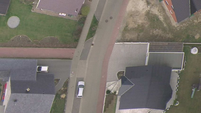
54   Advanced Video Coding for Next-Generation Multimedia Services
4    Video Coding

     performance for regular TV movies, an adaption of the concept for the current AVC codec is
     useful. To get an idea about where to integrate adaptations for Region of Interest coding, a
     basic understanding of hybrid video coders is necessary.

     2. Hybrid video coding
     Hybrid video coding was first introduced with H.261 in 1988 [7]. Since then, technical progress
     led to many improved versions of hybrid video coders, which were standardized later on as
     MPEG-1 [8], MPEG-2 [9], AVC [10] as well as its latest successor HEVC [11].

     A basic block diagram of a hybrid video coder can be found in Figure 2. It basically consists
     of three main stages: first a motion estimation followed by a motion compensated (MC)
     prediction step is performed. Afterwards the prediction error is transformed and quantized,
     e. g. with a DCT-based integer transform, to decorrelate the spatial signal. Finally, entropy
     coding is the last important step in modern encoders. All processing is done in a block-wise
     manner, which means that all pixels are grouped into larger units and consequently treated
     as one. A group of such blocks (i. e. 16 × 16 pel for AVC) is commonly known as macroblock.
     Two different types of video frames have to be distinguished, so called intra frames and inter
     frames. The former can be decoded independently from any other frame, while inter frames
     use temporal correlations between consecutive frames to predict the image content. In the
     following only inter frames will be further discussed, for most data reduction techniques use
     the correlations within those.
     The purpose of the aforementioned motion estimation/compensation process is to estimate
     the position of the current block in an earlier coded (reference) picture and only encode
     a motion vector representing its displacement along with the transformed and quantized
     error of the motion prediction, the so called residual. Motion estimation is employed
     block-wise by comparing the current block to a list of reference blocks and calculating
     the difference. The best match is then assigned in a Rate-Distortion-Optimization process.
     For complexity reasons an often used measure for this comparison is Sum of Absolute
     Differences (SAD), albeit the logarithmic measure Peak Signal-to-Noise Ratio (PSNR) is commonly
     employed for quality evaluation of coded video sequences compared to their uncompressed
     original. Even though block-wise motion compensated prediction is very efficient in general
                         s(n)     e(n)                  c(n)                            Entropy
                                         Transform             Quantization             Coding
                                  s(n)
                                                                           Inverse
                                                                          Transform

                                                                               e’(n)

                                                                               s’ (n)
                                                                                k
                                              Motion Compensated
                                                   Prediction
                                                                                        Entropy
                                                                                        Coding
                                                      Motion
                                                     Estimation

     Figure 2. Simplified block diagram of a hybrid video coder.
Region of Interest Coding for Aerial Video Sequences Using Landscape Models    55
                                     Region of Interest Coding for Aerial Video Sequences Using Landscape Models 5
                                                                                       http://dx.doi.org/10.5772/52904

                                                               ROI
                                                             Detection                            Sec. 3.1

                                                                    ROI Mask
      Video
        in
                            AVC
                                               FMO              SVC               GMC              Mesh
                            QP

                                             Sec. 3.2                          Sec. 4.1−4.2       Sec. 4.4

Figure 3. Schematic overview of ROI coding possibilities.

purpose coding, special scenarios can benefit from tailored solutions. In a number of real
life use-cases, a differentiation of the scene in fore- and background can improve coding
efficiency. Therefore, the background can be seen as a static scene (sprite image) which
has to be reconstructed at decoder side. Afterwards, any moving objects can be mapped
into the static background at appropriate positions. Systematic mapping errors caused by
an inaccurate model assumption can emerge at block boundaries. For different moving
objects with different directions contained in one macroblock, systematic problems occur,
too. As a technique to code fore- and background separately, sprite coding, which will be
explained in detail in Section 3.2, already existed in MPEG-4 and needed an adaption to
AVC. By implementing this, benefits from the GMC-based coding concept from MPEG-4 sprite
coding could be combined with the improved coding performance of AVC. Before being able
to code fore- and background however, working solutions to separate the scene into these
object layers have to be introduced.

3. Concept of ROI coding
A lot of research has been done in the field of segment- and object-based coding [12, 13].
Seeing that certain objects are indeed regions of interests, object-based coding can be
considered ROI coding, which promises to grant more efficient coding of aerial video
sequences (especially when employing landscape models). Therefore an overview of existing
ROI coding techniques is a good starting point to introduce this concept, before additional
assumptions for landscape model-based coding of aerial video sequences are presented.
The basic idea of Region of Interest (ROI) coding is to improve the quality of certain parts of the
video. Therefore it first has to be clear, what the important or interesting regions of the image
are, so that a fitting discriminatory factor to detect them can be determined. Afterwards, it
has to be decided on how the ROI is treated in contrast to the rest of the image. The following
sections are hence split according to these main issues:

1. How are ROIs detected?
2. How are ROIs encoded?

Figure 3 gives a schematic overview of the workflow including the different possibilities on
how to encode ROIs with references to the appropriate sections of this chapter.
56   Advanced Video Coding for Next-Generation Multimedia Services
6    Video Coding

                                           VOP 0                                   VOP 0
                                          Encoder                                 Decoder

              Video                                            bit stream                                       Video
               in       VOP                VOP 1                            De−    VOP 1             VOP         out
                                                         MUX
                      Formatter           Encoder                           MUX   Decoder          Compositor
                                                               Channel

                                           VOP 2                                   VOP 2
                                          Encoder                                 Decoder

                          global motion                                                     global motion
                           parameters                                                        parameters
                                          Encoder                                 Decoder

                                                VOP 0:    background sprite
                                                VOP 1:    object plane 1
                                                VOP 2:    object plane 2

     Figure 4. Simplified sprite-based MPEG4 coding.

     3.1. ROI detection
     The detection of ROIs can be arbitrarily realized, starting by the definition of fixed image
     positions (e. g. the center of the image) or skin color detection for teleconferencing systems [2,
     14] to more sophisticated methods, which include several preprocessing steps, as described
     in the context of screen content coding [15], or the employment of a human attention model,
     even. A neural network-based approach is employed in [16] to determine foreground and
     background blocks. In [17] the Sarnoff Visual Discrimination Model is introduced to detect the
     Just Noticeable Difference (JND) by taking into account several parameters such as the distance
     from the observer to the image plane, the eccentricity of the image in the observer’s visual
     field and the eye’s point spread function. For coding aerial sequences regions of interest are
     often moving objects, such as cars and people. Generally, an easy way to find motion in
     pictures is to subtract the current from the preceding frame. If the background is relatively
     static, only the moving objects of the frame are left after this step. If an additional threshold
     or filter is added to decide whether the changed region is just noise or an actual object,
     the detection becomes even more accurate. The movement of the camera also causes newly
     emerging areas within a video sequence, which is another ROI in aerial video coding.
     The suitable ROI detection method to determine a ROI depends on the application scenario.

     3.2. ROI encoding
     Different parts of one image may move into different directions, whereas motion vectors of
     objects with the same movement basically point in similar directions. These objects can be
     summarized as one object plane, in video coding referred to as Video Object Plane (VOP), as in
     MPEG-4 part 2 [18, 19]. VOPs can be of arbitrary shape and quality, thus different VOPs may
     be used for coding different ROIs (and the image background) independent of each other.
     To efficiently encode composed scenes containing one background and one or more
     foreground planes, the concept of sprites was introduced [20], see Figure 4. The sprite
     represents the background either statically or dynamically. A static background sprite is
     a (off-line) preprocessed mosaic image, assembled from the background images of the whole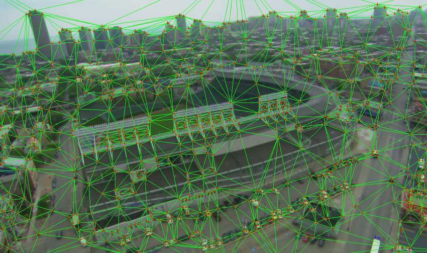
Region of Interest Coding for Aerial Video Sequences Using Landscape Models    57
                                    Region of Interest Coding for Aerial Video Sequences Using Landscape Models 7
                                                                                      http://dx.doi.org/10.5772/52904

Figure 5. Example for ROI coding (white line emphasizes the sharp region).

sequence, which is generated at encoder side. It is transmitted as the first frame of a sequence
and handled as a VOP. At decoder side, the background of the current frame is reconstructed
from the sprite image. Global motion parameters are employed to determine the section to
use from the sprite image. Afterwards, any other VOPs – containing foreground objects –
can be mapped into the current frame. Basically, dynamic sprites are very similar, but they
are able to change over time. The dynamic sprite is estimated during the encoding process
utilizing global motion compensation (GMC). The current background image is composed out
of an image generated from the warped sprite and the prediction error [21]. Any foreground
objects are subsequently mapped into the image as it is done for static sprites. A detailed
view into global motion estimation techniques will be given in Section 4.1.
Due to the mostly static landscapes in aerial video sequences, sprite coding can be quite
useful. Thus, an adaption of sprite coding to AVC is of interest. To understand, how
sprite-based-like coding can be introduced into a block-based coder, a closer look at certain
AVC features is needed:

In AVC the basic independently decodeable part of one image is called slice. It consists
of a group of macroblocks. The concept of Flexible Macroblock Ordering (FMO) initially was
introduced into AVC for error resilience. The idea of FMOs is to order macroblocks in well
defined different slices. Yet it also can be employed for ROI coding of different parts of
the video image, since different slices can be coded in different qualities. Instead of setting
the Quantization Parameter (QP) per slice, an alternative would be the direct QP variation on
macroblock level according to the importance of an image region (low QP for important
regions, higher QP for the rest). Since every QP change has to be signaled, this method is
expensive in terms of bitrate [15]. A similarly simple, yet effective approach is to discard all
residual data for non-ROI areas [22]. A basic assumption of this approach is, that the motion
vectors have to match the real motion. Bitrate saved for residual data can be redistributed to
improve ROI’s quality. Recent developments also investigate the ROI coding with scalability
features as e. g. proposed in [23].
All these approaches, which can be realized by a standard AVC coder, are based on the
redistribution of bits: to encode ROIs in higher quality than in general video coding, more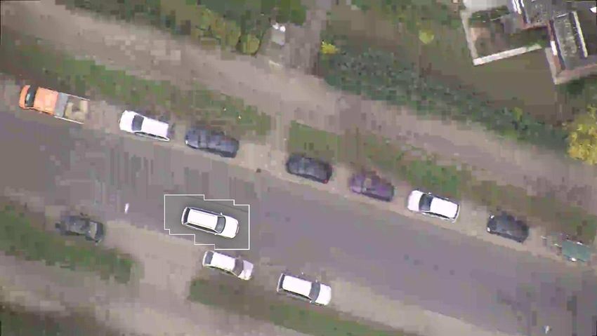
58   Advanced Video Coding for Next-Generation Multimedia Services
8    Video Coding

                     (a) Complete frame 176 from Stefan.                       (b)       Segmented   (c) Block raster for
                                                                               foreground.           coding.

     Figure 6. Example of object segmentation for test sequence Stefan [24].

     of the overall available bits are needed. These bits are saved at the cost of regions of lower
     importance whereby those are degraded in quality. An example of such a method is shown
     in Figure 5. A solution to overcome this issue for aerial video sequences is presented in
     Section 4.2.
     Figure 6 illustrates the principle of sprite coding. Figure 6(a) shows one example frame
     from the test sequence Stefan, the Region of Interest segmentation was determined with the
     approach described in [24]. Therein a gradient-based approach with pixel-wise accuracy,
     which relies on an eight parameter perspective motion model to register two images, is
     employed. The error between the current image and the adjacent motion-compensated
     reference image is then calculated to produce a coarse segmentation of the frame. After
     binarization and morphological filtering, any moved (foreground) object remains in the error
     image (Figure 6(b)). Based on this detection method some details or even parts of any
     ROI can get lost. For instance, in Figure 6(b) parts of the hair and legs are missing. For
     encoding, this segmentation is expanded to fit the macroblock structure (Figure 6(c)). [3] uses
     similar techniques but considers low-complexity constraints for landscape-based aerial video
     sequence coding, which results directly in a block-based structure. The complete coding
     system is explained in detail in Section 4.2.

     4. Video coding of aerial sequences using landscape models
     This chapter focuses on video coding methods suitable for the coding of aerial sequences.
     Therefore the idea of ROI coding is extended by employing landscape models, which can
     save additional bit rate when compared to general video coding. Also one weakness of
     other existing ROI coding approaches, which is to improve certain areas while degrading
     other image parts in quality, will be overcome – basically by reassigning some more bits to
     important regions than to non-important ones.
     A landscape model can be employed and used at en- and decoder side to estimate the
     movement of certain image parts. If the model is employed at both sides of the coding
     chain, only data not known from previous frames has to be transmitted. Image parts at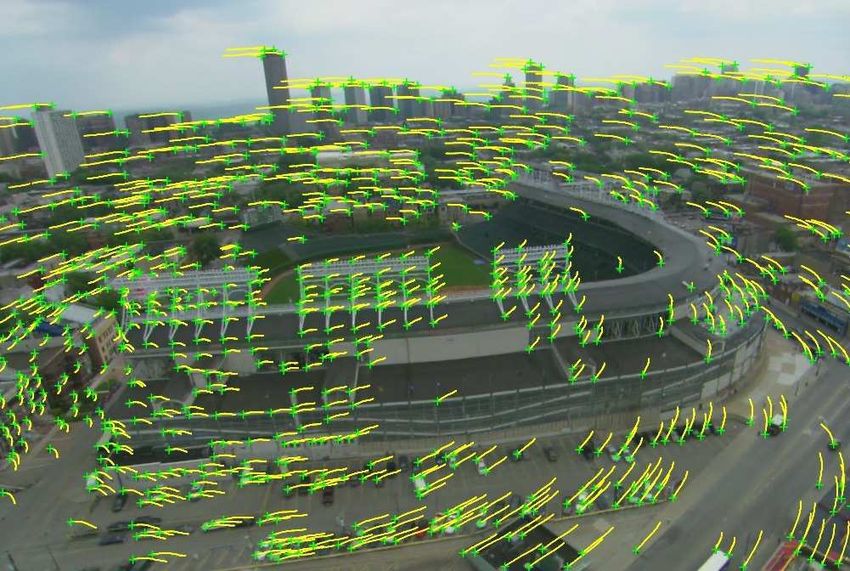
Region of Interest Coding for Aerial Video Sequences Using Landscape Models    59
                            Region of Interest Coding for Aerial Video Sequences Using Landscape Models 9
                                                                             http://dx.doi.org/10.5772/52904

the borders (New Areas) emerge in every frame and thus cannot be estimated from previous
data. Moving objects like cars also cannot be covered by a landscape model due to their
erratic movements. Handling these image parts as ROI is beneficial since existing ROI coding
techniques can be applied and extended.
A generic block diagram for landscape model-based coding is depicted in Figure 7: a
landscape model is applied to the video input stream, first. Although different landscape
models will be discussed later on, further processing steps basically stay the same. Landscape
extraction commonly begins with an estimation of the perceived global motion of the
background of a scene. Details will be given in Section 4.1. The parameters of the landscape
model necessary for decoding, have to be transmitted as side-information. In the case of a
planar landscape model (GMC-based approach) no additional landscape model information
beside the GMC mapping parameters are needed.
Simultaneously working Region of Interest Detectors are used for extracting different ROIs, such
as New Areas (ROI-NA) or Moving Objects (ROI-MO), which will be prioritized in the following
encoding. These two ROI detectors are specially tailored for aerial sequence coding and are
included in the block diagram, but in principle any ROI detector, e. g. shape-based detectors
for special buildings, can be added.
Before everything else, the benefits of general landscape model-based coding are introduced
and the concept of model-based coding is depicted. The estimation of the perceived
background motion is one essential part of it, hence a detailed explanation will be given
first. Afterwards, a closer look into a practical coding system employing a GMC-based
approach is taken, including detection of ROI, encoding and corresponding decoding. Finally,
different landscape models are introduced and their special advantages and disadvantages
are discussed.

4.1. Basic principles of background motion estimation
To estimate the global motion in a frame of a video sequence, it is necessary to know about
the movement of the camera, which is fixed at an airplane or UAV. Given the accuracy
limitations of GPS and drift problems of INS, features within the video sequence have to
be used to get information about the motion [25].
At the common speed and flight height of an UAV, most of the content of one frame is
available in the previous frame as well. This is illustrated in Figure 8.
To align two frames, there are several well-known possibilities to find significant features
within each frame, e. g. feature-based approaches like SIFT [26] or corner detectors such as
the Harris Corner Detector [4]. The latter was used in [3] and will be described in detail in the
following.
The Harris Corner Detector is employed to detect corners within a frames. This detector is
based on a two-dimensional gradient method which uses the luminance (gray values) within
the picture. Features are defined as corners with high gradients in horizontal and vertical
direction.
Afterwards,     a correspondence analysis is performed,            employing the KLT
(Kanade-Lucas-Tomasi) feature tracker [5, 27]. Based on a local optical flow method
the position of all features from frame k − 1 can be aligned with those in the consecutive
frame k.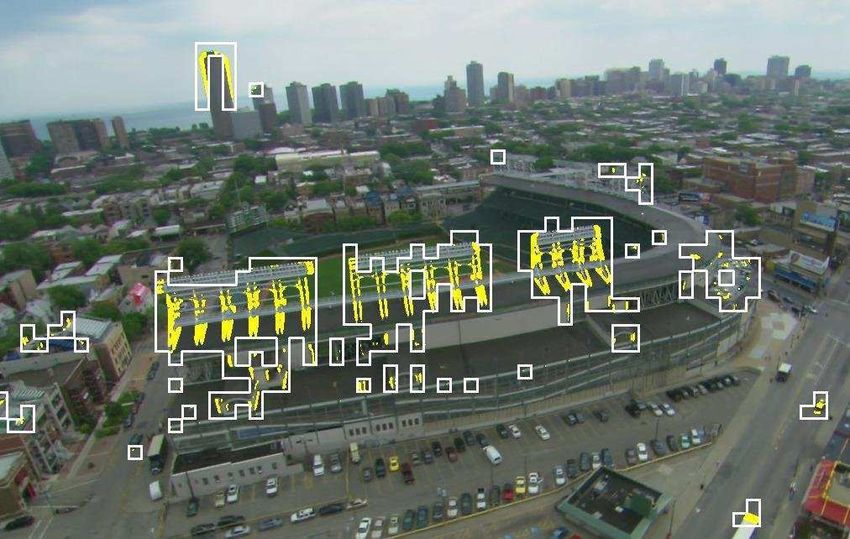
60   Advanced Video Coding for Next-Generation Multimedia Services
10 Video Coding

                                                                     ▲❛♥❞s❝❛♣❡ ▼♦❞❡❧

                                             ▲❛♥❞s❝❛♣❡ ▼♦❞❡❧
                                                                                          ●▼❈
                                                                                          ▼❛♣♣✐♥❣
                                            ❈✉rr❡♥t      ❘❡❢❡r❡♥❝❡                        ♣❛r❛♠✳
                                             ❢r❛♠❡       ❢r❛♠❡

                                ❘❖■✲◆❆                               ❘❖■✲▼❖
                                ❉❡t❡❝t♦r                             ❉❡t❡❝t♦r

                                      ◆❡✇ ❛r❡❛                             ▼♦✈✐♥❣ ♦❜❥❡❝t
                                      ✐♥❢♦r♠❛t✐♦♥                          ❛r❡❛ ✐♥❢♦r♠❛t✐♦♥
                                                                                                       ▼❯❳      ❊♥❝♦❞❡❞
                                                                                                                ❜✐t str❡❛♠

                                            ❘❖■ ❈♦❞✐♥❣ ❈♦♥tr♦❧

                                                        ▲✐st ♦❢ ❜❧♦❝❦s
                                                        t♦ ❜❡ ❝♦❞❡❞

         ❱✐❞❡♦                                                                            ❱✐❞❡♦
            ✐♥                                                                            ❜✐t str❡❛♠
                                               ❱✐❞❡♦ ❊♥❝♦❞❡r

     Figure 7. Block diagram of landscape model-based coding (dashed lines: optional, depending on the use-case). ROI-NA is a
     Region of Interest detector for New Areas (newly emerging areas within the picture, for example at the edge of one frame),
     whereas ROI-MO is a Region of Interest detector for Moving Objects, such as cars etc.

                                                                                        ♥❡✇ ❛r❡❛s t♦ ❜❡ ❝♦❞❡❞

                                                                                   sk
                                                                          s k −1
                                                                                         ✢✐❣❤t ❞✐r❡❝t✐♦♥

     Figure 8. Detection of new areas by global motion compensation (GMC).
Region of Interest Coding for Aerial Video Sequences Using Landscape Models 61
Region of Interest Coding for Aerial Video Sequences Using Landscape Models 11
http://dx.doi.org/10.5772/52904
Block-matching as described in [28] would be an alternative, wherein the blocks of one frame
are searched within the next one and their positions are used to align the frames. Seeing that
in aerial video material lots of blocks look similar speaks against using this approach, though.
4.2. Video coding using a planar landscape model
Since from big flight heights the movement at the ground seems approximately translational,
using a homography leads to a simple landscape model for the decoder, i. e. the landscape
is assumed to be planar.
First, a matching process of corners in two consecutive frames is performed as explained in
Section 4.1. With the assumption of a planar ground, it is possible to transform one entire
frame into another using 8 parameters (perspective or projective transform parameters),
Equation (1).
ak = ( a1,k , a2,k , . . . , a8,k ) T (1)
The projection describes for every pel x and y in frame k − 1 a matching pel ★✔
p = ( x, y) in the
succeeding frame k with the mapping parameter set a★✔k .
F ( ★✔
p , a★✔k ) =
a1,k · x + a2,k · y + a3,k a4,k · x + a5,k · y + a6,k
, (2)
a7,k · x + a8,k · y + 1 a7,k · x + a8,k · y + 1
The parameters a3 and a6 stand for a translational movement in direction of x and y, whereas
parameters a1 , a2 , a4 and a5 describe shearing and rotation.
The point-correspondences are used to register two consecutive frames and thus estimate
the global motion of the camera. Therefore, an overdetermined linear equation system is
set up for an estimation of the 8 parameters of the projective transform. By minimizing the
Mean Squared Error (MSE), Random Sample Consensus (RANSAC) [29] estimates the resulting
projection parameters, which are then used to align two frames and are employed for global
motion compensation.
Since with GMC only shifting of the background can be described, additional efforts for
coding of the areas not contained in the first frame have to be made. To cope with these image
parts, a New Area ROI detector (ROI-NA) is employed. Like this an adaption of MPEG-4 sprite
coding can be introduced into AVC as explained in [24]. [3] presented a similar approach
especially fitting for landscape model-based coding, taking into account the computational
possibilities on board of UAVs. Whereas the former approach was designed as a general
video coder, the latter utilizes the planarity assumption of aerial landscape video sequences
for further data rate reduction employing a GMC-based coding (without transmission of an
additional prediction error). This coding scheme will be summarized shortly in the following.
Drawbacks as well as their possible solutions are discussed in Section 4.4.
The block diagram of the coding scheme equals Figure 7 when replacing the block Landscape
Model with Global Motion Estimation & Compensation. In this case background representation
is similar to MPEG-4 dynamic sprites but employs improved AVC coding instead of MPEG-4.62 Advanced Video Coding for Next-Generation Multimedia Services
12 Video Coding
As mentioned above, the camera movement is estimated with global motion estimation in
the beginning. This estitmate is then used for detecting areas at border of the current frame
sk , which were not already part of the previous frame sk−1 . They are considered to be a
new area and marked as ROI. The decoder only needs information about the global motion
to warp the content of the previous frame to the current position. The new area is padded to
the appropriate position at decoder side and thus, a mosaic is generated (Section 4.2.1) from
which the complete current frame can be cut-out. This global motion compensated approach
not only prevents the retransmission of redundant image parts but also freezes the noise so
that data rate can be saved. On the downside moving objects like cars are also frozen at
the position of their first occurrence in the video sequence. To solve this a Moving Object
detector is employed (ROI-MO): a difference picture between two frames is derived in order
to detect moving objects and uncovered background. To reduce false detections because of
noise, the average of a 3 × 3 block is calculated and values below a predefined threshold t1
are considered to be noise. If a region is larger than a predefined minimum m, a moving
object is registered and the corresponding macroblock is additionally marked as ROI for
further processing. Any desired other detectors could be added to work in parallel, e. g.
shape-based ROI detectors for industrial buildings or image-based ROI detectors for hospitals
or the like.
The ROI Coding Control combines all macroblocks containing any ROI and forwards the
information to a video encoder, i. e. an AVC encoder. Thus, any macroblock (of size
16 × 16 pel) containing at least one ROI is considered to be encoded in high quality, whereas
other macroblocks are encoded in skip mode, i. e. not encoded at all.
4.2.1. Decoding and Visualization of a ROI Controlled Bitstream
Since AVC does not support global motion compensation which is employed to transform the
background image to the appropriate position, a GMC capable AVC decoder, here referred to
as ROI decoder, has to be used.
A block diagram of this ROI decoder is depicted in Figure 9.
❱✐❞❡♦ ▼❛♣♣✐♥❣
❇✐t str❡❛♠ ♣❛r❛♠❡t❡rs
❋r❛♠❡ ●❧♦❜❛❧ ▼♦t✐♦♥
❱✐❞❡♦ ❉❡❝♦❞❡r
❞❡❧❛② ❈♦♠♣❡♥s❛t✐♦♥
▼♦t✐♦♥ ❝♦♠♣✳ ▼❛♣♣✐♥❣
◆❡✇ ❆r❡❛ ♣❛r❛♠❡t❡rs
■♥t❡❧❧✐❣❡♥t
▼♦✈✳ ❖❜❥✳ ◆❡✇ ❆r❡❛
▼❡♠♦r② ❢♦r ▼♦s❛✐❝
❋r❛♠❡ ❝✉t
❢r♦♠ ♠♦s❛✐❝
❈♦♠❜✐♥❡ ◆❡✇ ❆r❡❛
❛♥❞ ▼♦✈✐♥❣ ❖❜❥❡❝ts
❱✐❞❡♦ ♦✉t
Figure 9. ROI decoder for combining GMC background with additional moving objects [3].Region of Interest Coding for Aerial Video Sequences Using Landscape Models 63
Region of Interest Coding for Aerial Video Sequences Using Landscape Models 13
http://dx.doi.org/10.5772/52904
It basically shows that a video or a mosaic is created from the ROI-NA encoded data and
afterwards ROI-MO blocks are inserted into the resulting video sequence or the mosaic at
appropriate positions, respectively. This method is comparable to MPEG-4 sprite decoding
and inserting other objects, e. g. from other VOPs. It is necessary to transmit the
mapping parameters as side-information to the receiver in order to apply a GMC at the
decoder. This can be done without modification of the standardized bit-stream when
encapsulating the mapping parameters as SEI (Supplemental Enhancement Information) in the
data stream. Information about the position of moving objects containing macroblocks has
to be transmitted also.
(a) Generation of the decoded video sequence out of (b) Principle of creating a mosaic. Black lines between
new area. frames are for illustration purpose.
Figure 10. Principle of decoding a ROI coded video sequence (sequence from 500 m flight height).
To reconstruct the initially intra coded frame from the background sprite, here referred to as
mosaic, new area macroblocks are registered employing the transmitted mapping parameters
to their final position in the mosaic. Like this the mosaic is growing with every new area
stripe. Figure 10(a) shows the principle of stitching stripes of ROI-NA together. Figure 10(b)
gives a closer look at the growing-process of the mosaic: it shows some succeeding stripes
of new area which are stitched to the reference frame. The black marker lines between the
single frames only serve illustration purposes.
The receiver can generate a decoded video sequence from the created mosaic. Therefore,
the position of the current frame in the mosaic back to the last reference frame has to
be derived using global motion parameters. Using the global coordinates of the current
background frame as well as the binary mask for the current frame indicating the positions
of macroblocks with moving objects (and the uncovered background as well), an entire frame
with high-resolution background and moving objects can be reconstructed.
A complete mosaic is shown in Figure 11, with the level of details shown in magnification.
The mosaic has a size of 21104 × 4500 pel, which corresponds to about 30 seconds of flight in
a flight height of 350 m.
A decoded frame from the ROI decoder is shown in Figure 12, whereas white lines emphasize
ROI[3].64 Advanced Video Coding for Next-Generation Multimedia Services
14 Video Coding
Figure 11. Mosaic and magnification (sequence from 350 m flight height).
Figure 12. Output frame from the ROI coding system, white lines emphasize ROI.
4.2.2. Limits of Global Motion Compensation-based Techniques
The previous approach works quite well for planar landscapes, where the coder is able to
project one frame into another by use of global motion compensation. However, as the
real landscape often can’t be approximated by the assumption of a planar ground, several
model violations can occur in aerial video sequences. Especially if recorded from a lower
altitude, where the perceived diverging speeds of different image areas become obvious,
the simplifications made do not hold true. An illustration of such a case can be found
in Figure 13: while global motion compensation can handle most of the similar housingsRegion of Interest Coding for Aerial Video Sequences Using Landscape Models 65
Region of Interest Coding for Aerial Video Sequences Using Landscape Models 15
http://dx.doi.org/10.5772/52904
(a) Example frame including correctly classified moving objects and wrongly classified static
structures.
(b) Magnification of one static structure
detected as moving.
Figure 13. Limits of translatory block matching. Yellow: motion candidates, white rectangles: areas found to contain moving
objects. Test sequence Chicago.
correctly, the high structures of the stadium in the foreground are closer to the camera and
seem therefore to be moving faster when compared to their surroundings (Figure 13(b)).
Their approximated motion doesn’t fit the global estimate and as a consequence the
structures are classified as moving objects.
Since the corresponding macroblocks are handled as ROI, many false positive macroblocks
have to be encoded and transmitted, leading to an increased data rate. To keep the needed
bandwidth constant when faced with the worst case scenario in which all parts of the scene
were recognized as ROIs, the overall quality of the image would have to be degraded. To
avoid false detections and keep the transmitted data to a minimum while preserving details,
other ways to model the surface of the scene had to be explored.66 Advanced Video Coding for Next-Generation Multimedia Services
16 Video Coding
(a) Selected features (green crosses) and their (b) Green regions are considered background, while
trajectories (yellow lines). other colors are candidates for moving objects.
Figure 14. Feature selection, tracking (left) and clustering results (right).
4.3. Video coding using piecewise approximation of the Earth surface by planes
The global motion approach which uses only a single plane to approximate the earth
surface leads to mistakes as described in Section 4.2.2. Several objects in aerial video
sequences, houses for example, however, can be described as piecewise planar and therefore
an approximation using more than just one plane seems natural.
One way to realize this is by computation of oriented tangential planes for a number of
significant points as described in [30] and using those planes as a local linear approximation
of the surface. Another method is introduced by [31], where the production of a piecewise
planar model from a continuous aerial video stream is done in three stages: First half-planes
are computed, afterwards lines are grouped and completed based on those planes, followed
by a plane delineation and verification process which concludes the model building process.
In both cases motion would be estimated and compensated for each of the computed planes
separately in the same way described for the single-plane approach. A more purpose-built
approach is described by [32], in which planar surfaces are first detected and segmented
within a point cloud to seek out buildings from an aerial sequence. Using this step as a
priori information could help to compensate the perceived motion of the different image
parts, when motion is estimated for all of those found surfaces instead of just the assumed
base plane.
4.4. Video coding using a mesh-based approach
When approximating a more complex surface structure, a sophisticated piecewise approach
with whole planes often ignores smaller faces and becomes computationally difficult. In the
case of UAVs, this can easily lead to problems, as there is only so much computational capacity
available on-board. An alternative is using the points and correspondences already available
through the corner detector and tracking mechanism introduced earlier for recognizing the
moving objects. In Figure 14(a) an example for selected features is shown by the green
crosses. The yellow lines mark the trajectories on which those features have moved over
time.
The tracked features lead to a motion vector field which has to be cleared of outliers that were
caused by false tracking. This is done by testing the motion vectors against a motion modelRegion of Interest Coding for Aerial Video Sequences Using Landscape Models 67
Region of Interest Coding for Aerial Video Sequences Using Landscape Models 17
http://dx.doi.org/10.5772/52904
and remove vectors that are not supported by it. Typically the model is a projective transform
which is then treated by RANSAC for a global solution. In the case of a mesh-based motion
estimation however, there is no global solution without a full 3D model available, which
means another approach has to be chosen here. In [33] a region growing approach based
on vector field smoothness is described: the spatial distance (Equation (3)) and displacement
difference (Equation (4)) of adjacent motion vectors are compared to an adaptive threshold.
k~rk ( x, y) − ~nk ( x, y)k < td1 (3)
kd~~rk ( x, y) − d~~nk ( x, y)k < td2 (4)
~rk ( x, y) describes the position of the classified motion vector nearest to the yet unclassified
motion vector ~nk ( x, y) in frame k, while d~~rk and d~~nk are displacement vectors of the associated
motion vectors pointing to their position in the preceding frame. Through this representation
the movement of a region is only described by the motion vectors at its boundaries. In
contrast to this, block-based methods use the motion vector from the center of the block as
a representation. If they are smaller than the threshold, the vectors are clustered into one
object, otherwise they remain unclassified. In case none of the unclassified motion vectors
fulfills the requirements mentioned, a new object is created. Large regions, in which the
same motion vector prevails, are treated as background, smaller regions are considered to be
potentially moving objects. Objects containing less than a certain threshold are considered
outliers and are consequently removed. In Figure 14(b) the results of the process are given.
At this point, only the motion of the selected feature points is known. With the help of
these features in combination with the information about their movement, the displacement
of each pel (xtk , ytk ) of the image can be interpolated. The found feature points form a
point cloud, which can be transformed into a mesh through a triangulation algorithm ([6]).
Delaunay Triangulation, as described in [34], is one example to complete this task. This
method basically tries to connect the points of a plane in such a manner, that no other
point within the circumcircle of a triangle exists and the minimum angle of all triangles
gets maximal at the same time. The mesh derived for the stadium example can be found in
Figure 15.
The planar assumption is then used on all of the resulting patches, which is an accurate
estimation if the patches are small. By defining this, it is now possible to model each patch
by an affine transform, whose parameters Atk , Btk , Ctk , Dtk , Etk and Ftk can be calculated
using the feature points that span the triangle tk in the current frame k, as well as their
position (xtk−1 , ytk−1 ) in the preceding one (k − 1). Each position of a pel within a triangle can
be connected to its eqivalent coordinate in the old frame via
x t k −1 x tk
= T tk · + b tk (5)
y t k −1 y tk
wherein68 Advanced Video Coding for Next-Generation Multimedia Services
18 Video Coding
Figure 15. Triangulated mesh from selected features.
Atk Btk
T tk = (6)
Ctk Dtk
and
Etk
b tk = . (7)
Ftk
To get the integer position pixel values, a final interpolation has to be performed. One
example to get the needed accuracy is the usage of a two-stage filter as proposed in [6],
where half-pel positions are calculated using a six tab Wiener filter and quarter-pel positions
through bilinear filtering. Moving objects within the scene can be found by comparing
the resulting motion compensated frame with the preceding one by e.g. sum of squared
differences (SSD) and a subsequent low-pass filtering. Motion candidates are then determined
by thresholding. When examining the result of the moving object detection hailing from the
mesh-based method (Figure 16(a)) in contrast with the results from the earlier introduced
single-plane approach (Figure 13), it becomes apparent that the number of falsely detected
moving objects has reduced quite a lot. Only smaller regions of the high structures are still
misclassified, the moving cars, which doesn’t fit the model, however are correctly recognized.
Overall the mesh-based approach leads to about 90 % less false positive detections.
Some moving objects however show only little motion from one frame to the next. If their
surface is relatively uniform, as it is the case with car roofs for example, a comparison
between adjacent frames would only show pieces of the object moving. This is because
only changing parts of the image can be recognized by differencing. If a uniform area
is moved though, chances are, that the new position overlaps with the old one, so that
the difference in these parts equals zero. As a consequence, truly changing areas can beRegion of Interest Coding for Aerial Video Sequences Using Landscape Models 69
Region of Interest Coding for Aerial Video Sequences Using Landscape Models 19
http://dx.doi.org/10.5772/52904
(a) Mesh-based method. (b) Mesh-based method combined with mosaic approach.
Figure 16. Result of moving object detection. Yellow: motion candidates, white rectangles: areas found to contain moving
objects.
rather small, so that a filter threshold to get rid of false motion has to be quite low to not
loose them. If more candidates in valid regions would be available, this threshold could
be raised so that falsely detected moving regions could be discarded while the real moving
objects are kept. By combining the mosaicking technique described in Section 4.2.1 with the
mesh-based approach, this can be achieved. First a motion compensated reference picture
from the preceding N frames is created by tracking the features and mapping them into the
coordinate system of the current frame. With temporal distance as a weighting factor for the
pixel values, the emerging image has the perspective of the current frame, only created from
the previous frames. Moving object areas, which were already identified via differencing for
preceding images or the aforementioned clustering step, are skipped during the mapping
process, so that those areas are removed from the resulting reference image. If now the
difference between the reference picture and the current image is calculated, the number of
motion candidates increases, so that a higher noise filtering threshold can be used. This in
turn leads to less misclassified regions and therefore less data that has to be transmitted. The
result can be seen in Figure 16(b).
An option yet to be explored for coding purposes is the usage of a full 3D model instead
of the comparatively simple mesh just described. To get the mesh as it is to the decoder
side, a transmission of such a model would be necessary anyway, so its advantages could
as well be used. 3D reconstruction from image sequences via depth estimation as described
in [35] for example could be an alternative way to get such a model. Otherwise the mesh
would be used as a base and turned into a 3D model by mapping texture from the video
sequence onto it. Eventhough computationally expensive, the availability of such a model
could provide several advantages, such as a better recognition of moving objects and a better
understanding of the area for the following processing steps in a more elaborate system,
wherein the coding and transmission of image sequences is only one step.
5. Results
In this section improvements in terms of coding efficiency for aerial video sequences
employing the methods introduced in Section 4 will be evaluated.
Therefore, the coding efficiency of the AVC implementation x264 [36] is compared to an
encoder optimization which suppresses all residual data for non-ROI blocks, first. This70 Advanced Video Coding for Next-Generation Multimedia Services
20 Video Coding
42 42
AVC codec
AVC w/o resid. in non−ROI
40 40 Mesh codec
38 38
PSNR in dB
PSNR in dB
36 36
34 34
AVC codec
32 AVC w/o resid. in non−ROI 32
Mesh codec
GMC ROI codec
30 30
600 800 1000 1200 1400 1600 600 800 1000 1200 1400 1600
Data rate in kbit/s Data rate in kbit/s
(a) RD plot for AVC-based systems, only for (b) RD plot for comparison of mesh coding system with AVC
ROI areas. Mesh-based coder for comparison. for the entire frame.
Figure 17. Rate-distortion (RD) diagrams for ROI-based coding systems and mesh coding system, each compared with AVC for
very low bit rates.
(a) Reconstructed image from the mosaic.
(b) Detail of the (c) Detail of
original image. the GMC-based
reconstr. image.
Figure 18. Mapping errors due to perspective distortions in the GMC-based coding system.Region of Interest Coding for Aerial Video Sequences Using Landscape Models 71
Region of Interest Coding for Aerial Video Sequences Using Landscape Models 21
http://dx.doi.org/10.5772/52904
is expected to provide improved ROI quality at cost of non-ROI quality (Section 3.2).
Additionally, the GMC-based approach is included in the comparison, which encodes all
non-ROI in skip mode. Thus, apart from signalization, the entire data rate can be used to
encode the ROIs (Section 4.2). Both encoders are controlled by the external ROI Coding Control
(cf. Figure 7).
Bitstreams were created and decoded either with a standard video player or, for the
GMC-based implementation, with a special ROI decoder (cf. Section 4.2.1). For quality
comparison, the widely used image difference measure Peak-Signal-to-Noise Ratio (PSNR) can
not be used for entire frames, because the output of the GMC-based ROI decoder is not
pel-wise the same as the input – especially at object borders. To overcome this issue and
to give a realistic performance analysis, only the PSNR of those macroblocks containing a
ROI is considered for different coding systems (Figure 17(a)). Mapping errors caused by the
projective transform of non-planar frames into a mosaic occur. Thus, any object not matching
the planarity assumption causes shifted edges as depicted in Figure 18. The GMC-based
approach however, was designed to buy a reduction of data rate for the price of such errors
which are considered to be not as grave as they do only occur in small partitions of the frame.
This can be seen in Figure 18(a).
For ROI, the encoder without residual coding performs slightly better for very low bit rates
(≤1500 kbit/s) than the (unmodified) AVC coder, as was expected. Since the residual isn’t
coded anymore, block artifacts become larger. They also serve as a base for motion vector
derivation, which leads to an inhomogeneous motion vector field that is expensive to code
with the AVC differential encoding. Thus, only little additional gain can be gathered by
discarding residual data for non-ROI. The GMC-based approach outperforms both opponents
by far in terms of PSNR at any bit rate, since significantly more bits are available to encode a
very small image area (compared to the entire frame).
Informal subjective tests support these findings and demonstrate the achievable quality. The
resulting image quality after ROI coding and decoding is shown once for a magnification of
non-ROI (Figure 19) and once for ROI areas (Figure 20), respectively. For this comparison all
coders were operated with the same parameters, except for the Quality Parameter (QP), which
was adjusted for each coder to match an overall bit rate of about 1000 kbit/s.
Starting with the results of non-ROI (Figure 19), a magnified outtake of the original frame is
shown as it was recorded by a camcorder mounted to a motorized glider in Figure 19(a). A
magnified outtake of the coding result of the unmodified AVC coder is printed in Figure 19(b).
The loss of details is obvious as can be seen e. g. in the tree and with the man holes on the
right (light green/dark blue markers). Essentially, the modified AVC codec with disabled
residual coding in non-ROIs delivers similar image degradations as the previous codec. But
since no residual information was employed, additional block errors occur e. g. at the street
light (Figure 19(c), red arrow). The ROI controlled GMC-based codec from Section 4.2) is able
to provide the highest level of details for the entire frame (Figure 19(d)).
For ROI (Figure 20), the results look quite similar. Figure 20(a) again is the reference,
representing the recorded quality. In contrast to the results for non-ROI, the standard
AVC performs worst, because the available bitrate has to be spread over the entire frame
(Figure 20(b)) leading to heavy loss of details (e. g. markers at the road, dark red ellipses),
whereas the modified AVC codec (without residual coding for non-ROI) is able to preserve
slightly more details at a relatively bad overall quality (Figure 20(c)). The ROI controlled72 Advanced Video Coding for Next-Generation Multimedia Services
22 Video Coding
(a) Original. (b) AVC. (c) AVC w/o residual (d) GMC-based ROI
coding for non-ROI. coding with ROI
Control.
Figure 19. Quality visualization of non-ROI areas (outtakes) coded with 1000 kbit/s with different coders:
(a) Original
(b) AVC encoded and decoded
(c) Modified AVC: coding of non-ROI blocks without residual
(d) GMC-based ROI coding using ROI Control from Section 4.2
(a) Original. (b) AVC. (c) AVC w/o (d) GMC-based ROI
residual coding for coding with ROI
non-ROI. Control.
Figure 20. Quality visualization of ROI areas, here outtakes of new area, coded with 1000 kbit/s with different coders:
(a) Original
(b) AVC encoded and decoded
(c) Modified AVC: coding of non-ROI blocks without residual
(d) GMC-based ROI coding using ROI Control from Section 4.2Region of Interest Coding for Aerial Video Sequences Using Landscape Models 73
Region of Interest Coding for Aerial Video Sequences Using Landscape Models 23
http://dx.doi.org/10.5772/52904
GMC Mesh
One plane assumption Multiple plane assumption
Mosaic creation of planar landscapes Mosaic containing 3D structures can be
only derived
Adapts to global motion Adapts to local motion
Coarse MO-classification results Refined classification results of MO
Very robust Sensitive to unremoved outliers
Easy computation More complex computation
Table 1. Differences between GMC-based and mesh-based approach.
GMC-based codec (Section 4.2) also performs best, since it is able to provide full spatial
resolution over the entire frame (Figure 20(d), light green ellipses). For aerial video sequences
in full HDTV resolution, with a GMC-based ROI coder, a bit rate of 0.8–2.5 Mbit/s at 1000 kbit/s
(depending on the sequence) can be reached, which is much less than the bit rate needed for
detail preserving regular AVC video coding.
In Section 4.4 mesh-based coding was presented as an alternative to the GMC approach. The
main differences between those two are summarized in Table 1.
To make use of the mesh-based concept, motion vectors as well as residual data have to
be transmitted from the encoder to the decoder. Seeing as the decoder already knows the
preceding image when decoding the current one, a transmission of the feature points isn’t
necessary. Finding the mesh grid points at the decoder can be achieved by the same steps
used at encoder-side, which were described in Section 4.1.
[37] showed, that for a QP of 30 nearly 20 % of the data rate of a video is needed for the
coding of motion vectors. For mesh-based coding only a fourth of the data rate necessary for
the transmission of motion information in AVC is needed. This is because only motion vectors
for the grid points of the mesh have to be taken into account in contrast to sending motion
vectors for every block. Another advantage is the omission of modes and the fact, that the
signaling of how the image is divided for coding isn’t necessary anymore. The residual is
thought to be equally big for both methods.
In Figure 17(b) a comparison between mesh and AVC coding is performed. It has to be noted
that in this plot the PSNR for the entire frame was used, in contrast to using the “quality” of
ROIs only in Figure 17(a). It is obvious that the mesh is able to achieve a better overall PSNR
at any bitrate when compared with the AVC coder. Though the bitrate of the GMC-based
approach is still below this of the mesh for the same PSNR, the reconstructed mesh image
doesn’t show perspective distortions anymore. Overall, compared to AVC, a reduction of
data by about 10 % when using the mesh-based approach seems realistic, taking into account
the findings of [37].
6. Conclusion
In this chapter, an improvement of coding efficiency for standardized video coding is shown
for user scenarios, in which a discrimination between Regions of Interest and background is
reasonable. Aerial video sequences, as captured e. g. by an airplane or an Unmanned AerialYou can also read