USE OF LIQUID NITROGEN AS WILDFIRE SUPPRESSANT - Northeastern ...
←
→
Page content transcription
If your browser does not render page correctly, please read the page content below
USE OF LIQUID NITROGEN AS WILDFIRE SUPPRESSANT

                          A Thesis Presented
                                   by

                               Aobo Liu

                                   to

      The Department of Mechanical and Industrial Engineering

                in partial fulfillment of the requirements
                            for the degree of

                           Master of Science

                                   in

                       Mechanical Engineering

                       Northeastern University
                        Boston, Massachusetts

                               April 2021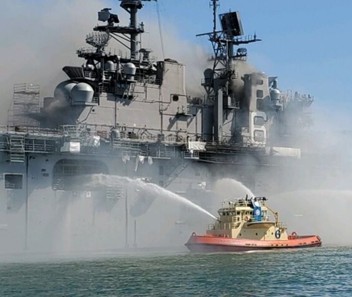
To my parents and Zengyao.

            i
Contents

List of Figures                                                                                                  iv

List of Tables                                                                                                   vi

Nomenclature                                                                                                     vii

Acknowledgments                                                                                                  ix

Abstract of the thesis                                                                                            x

1   Introduction                                                                                                  1
    1.1 Motivation . . . . . . . . . . . . . . . . . . . . . . . . . . . . . . . . . . . . . . .                  1
    1.2 Background and Previous Work . . . . . . . . . . . . . . . . . . . . . . . . . . .                        4
    1.3 Research Objective and Overview . . . . . . . . . . . . . . . . . . . . . . . . . .                       7

2   Small-Scale Experiments and Results                                                                           9
    2.1 Experiment Facility and Procedure . . . . . . . . . . . . . . . . . . . . . . . . . .                     9
    2.2 Experiment Results and Discussion . . . . . . . . . . . . . . . . . . . . . . . . . .                    10

3   Theory                                                                                                       13
    3.1 One-Hour Fuel and Safety Operation Distance . . . . . . . . . . . .      .   .   .   .   .   .   .   .   14
    3.2 Mechanical Breakup and Breakup Length of a Liquid Jet . . . . . .        .   .   .   .   .   .   .   .   15
    3.3 Preliminary Model Formulation and Validation . . . . . . . . . . .       .   .   .   .   .   .   .   .   18
        3.3.1 Preliminary Model of a Vertically Falling Spherical Droplet        .   .   .   .   .   .   .   .   18
        3.3.2 Model Validation . . . . . . . . . . . . . . . . . . . . . . .     .   .   .   .   .   .   .   .   20
    3.4 Droplet Evaporation Model After Primary Jet Breakup . . . . . . .        .   .   .   .   .   .   .   .   21

4   Simulation Results and Analysis                                                                              24
    4.1 Baseline Cases of LN2 Droplet Motion and Evaporation . . . . . . . . . . . . . .                         24
    4.2 Performance of the LN2 Droplet When tackling the One-Hour Fuel Fire . . . . . .                          27
        4.2.1 Effect of Droplet Type and Size on the Flight Distance and Evaporation . .                         27
        4.2.2 Effect of LN2 Droplet Initial Velocity on the Flight Distance and Evaporation                      33
        4.2.3 Effect of LN2 Droplet Injection Angle on the Flight Distance and Evaporation                       35
        4.2.4 Effect of Thermal Radiation on the Droplet Flight Distance and Evaporation                         38

                                                  ii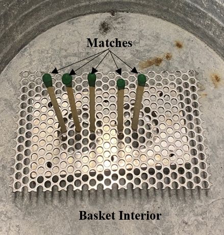
5   Conclusion           42

6   Future Works         44

Bibliography             46

                   iii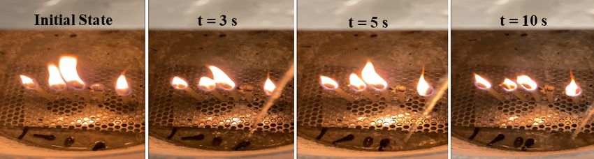
List of Figures

 1.1   Wildfires at the WUI can cause widespread human loss and immense destruction .              3
 1.2   Firefighters spent four days battling a raging fire aboard the Bonhomme Richard
       warship, spraying water to lower decks from side openings . . . . . . . . . . . . .         4
 1.3   P-T diagram of the nitrogen . . . . . . . . . . . . . . . . . . . . . . . . . . . . . .     6

 2.1   Experimental setting for simulating the fires in an enclosure . . . . . . . . . . . . .    10
 2.2   Laboratory experiments in a small home-made exposure. A small jet of water or
       liquid nitrogen was used to extinguish fires of 5 matches. The jet was either aimed
       blindly at a random point inside the enclosure (Cases a and b), or it was targeted
       directly on the matches (Cases c and d) . . . . . . . . . . . . . . . . . . . . . . . .    12

 3.1   Schematic diagram of primary breakup and secondary atomization [24] . . . . . .            16
 3.2   The Shadowgraph near the tip of a turbulent water jet in quiescent air (We = 33,100,
       d = 4.8 mm, at a distance of 1,040 mm from the jet exit) [25] . . . . . . . . . . . .      17
 3.3   The comparison of simulation results and experimental data from Awonorin [35] .            21

 4.1  Droplet velocity profiles along x and y directions. The air temperature is 150°C and
      initial horizontal velocity is 10 m/s . . . . . . . . . . . . . . . . . . . . . . . . . .   25
 4.2 Trajectory and diameter profiles of 2-mm LN2 droplets. The air temperature is 150°C
      and initial horizontal velocity is 10 m/s . . . . . . . . . . . . . . . . . . . . . . . .   25
 4.3 Trajectory and diameter profiles of 2-mm LN2 droplets under various air temperatures         26
 4.4 Schematic diagram of the position of the droplets and the flame shape . . . . . . .          28
 4.5 Hypothetical air temperature distribution profiles (linear and parabolic) near the
      one-hour fuel fire . . . . . . . . . . . . . . . . . . . . . . . . . . . . . . . . . . .    29
 4.6 Trajectory and diameter profiles of water and LN2 droplets under linear temperature
      distribution . . . . . . . . . . . . . . . . . . . . . . . . . . . . . . . . . . . . . .    30
 4.7 Percentage of remaining mass of LN2 and water droplets when approaching the fire
      under linear temperature distribution . . . . . . . . . . . . . . . . . . . . . . . . .     30
 4.8 Trajectory and diameter profiles of 2-mm and 3-mm LN2 droplets under different
      temperature distribution patterns . . . . . . . . . . . . . . . . . . . . . . . . . . .     32
 4.9 Trajectory and diameter profiles of the 2-mm LN2 droplets with various initial velocities    34
 4.10 Trajectory and diameter profiles of the 2-mm LN2 droplets with various injection
      angles . . . . . . . . . . . . . . . . . . . . . . . . . . . . . . . . . . . . . . . . .    36

                                               iv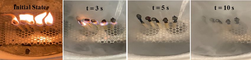
4.11 Trajectory and diameter profiles of the LN2 droplets under the effects of thermal
     radiation and convection . . . . . . . . . . . . . . . . . . . . . . . . . . . . . . .   40

                                             v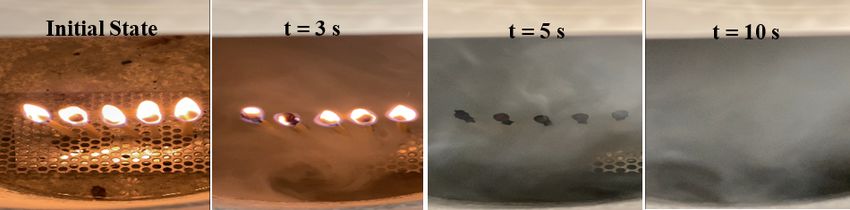
List of Tables

 1.1   Thermophysical properties of water and liquid nitrogen . . . . . . . . . . . . . . .     5

 4.1   Boundary conditions to investigate the effect of droplet type and size . . . . . . . .   29
 4.2   Boundary conditions of LN2 droplets to investigate the effect of the initial velocity    33
 4.3   Boundary conditions of LN2 droplets to investigate the effect of injection angle . .     36
 4.4   Boundary conditions of LN2 droplets to investigate the effect of thermal radiation .     40

                                               vi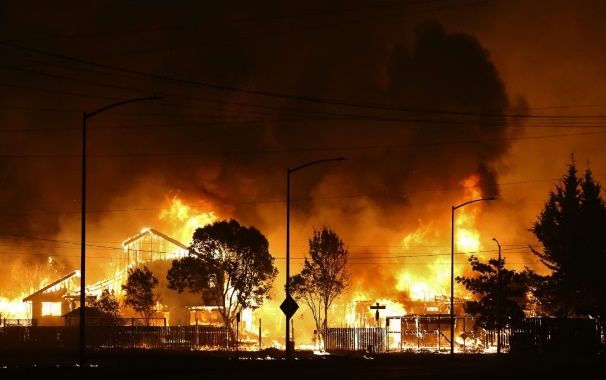
Nomenclature
                                  Dv
Re           Reynolds number,
                                  va
VF           View factor

v       vx    vy Velocity and its components along x and y directions (m/s)

x       y    Horizontal and vertical replacements of the droplet after the primary breakup (m)

Q̇           Heat release rate (kW)

q̇ 00        Heat flux (kW/m2 )
                               Cpg µg
Pr           Prandtl number,
                                kg
µg           Dynamic viscosity of gas (Pa·s)

ρf           Air density (kg/m3 )

ρl           Jet density (kg/m3 )

ρp           Droplet density (kg/m3 )

σ            Surface tension (N/m)

A            Area of the sphere (m2 )

Cpg          Specific heat of gas (kJ /K)

Cd           Drag coefficient of the sphere

D            Droplet diameter (m)

d            Nozzle diameter (m)

Dp           Pool diameter (m)

F            The net force acting on the droplet (N)

Fb           Buoyancy force (N)

Fd           Drag force (N)

                                                       vii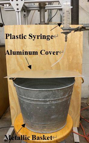
Fe     Force acting on the droplet due to evaporation (N)

Fg     Gravity force (N)

g      Gravitational acceleration (m/s2 )

hfg    Latent heat of evaporation (kJ/kg)

kg     Thermal conductivity of gas (mW/m·K)

Lf     Flame height (m)

Lx     Jet breakup length (m)

m      Droplet mass (kg)

p      Droplet momentum (kg·m/s)

Qrad   Radiative energy absorbed by the droplets (kW)

R      Distance from the fire center (m)

t      Time (s)

Tp     The temperature of the droplet surface (K)

T∞     Ambient air temperature (K)

va     Kinematic viscosity of air (m2 /s)

Xr     Radiant fraction

                                               viii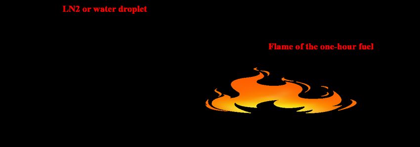
Acknowledgments

          I would like to express my sincere thanks to my thesis advisor, Professor Yiannis Levendis

and the thesis committee members, Professor Michael Delichatsios and Dr. Mary Delichatsios. Your

patient instructions always inspire me to do my research and your invaluable guidance consistently

led me through the unknown with profound insights. I also appreciate your recognition and advice

for my thesis presentation. I definitely could not make this far without your priceless assistance.

          I would like to thank my dear parents, Shinian and Hongmin, for their love and great faith

in me.

          Zengyao, I desire to share my greatest gratitude for your love and accompany for the past

six years. I love you.

          I also want to show appreciation to my friend at Northeastern, Dongchuan, you are my

best friend here in Boston. I could not finish my thesis without your assistance. Finally, I would like

to extend my appreciation to everyone who ever helped me at Northeastern. Aidin, thank you for

purchasing the liquid nitrogen sprayer for me. Di, thank you for finding the liquid nitrogen for me.

                                                  ix
Abstract of the thesis
USE OF LIQUID NITROGEN AS WILDFIRE SUPPRESSANT
by
Aobo Liu
Master of Science in Mechanical Engineering
Northeastern University, April 2021
Yiannis A. Levendis, Michael Delichatsios, Advisor
In recent years, all kinds of fire have become one of the most severe threats to human
beings and properties. Several methods are being used to extinguish the fires. Water, the most
commonly used fire suppressant, has been proven to be of limited effectiveness when tackling some
challenging types of fires, such as forest fires and industrial fires. Chemical foam, another popular
fire extinguishment agent, causes environmental contamination after the fire is quenched. Liquid
nitrogen (LN2) is a cryogenic fluid that is widely utilized in industry, and some of its characteristics
such as high volatility and low temperature showcase its potential to be a novel fire suppressant. It
can be produced readily from deep refrigeration of air and it is environmental-benign. In this thesis, a
small-scale experiment was performed to investigate the feasibility and effectiveness of using liquid
nitrogen jet as a fire suppressant. Then, a numerical simulation was carried out to determine the fate
of liquid nitrogen droplets upon a jet breakup. In this calculation, the effects of the parameters such
as ambient air temperature, initial droplet velocity, droplet size, droplet injection angle, and thermal
xradiation on the droplet flight distance and evaporation rate were studied. The experimental results
demonstrate the superior performance of LN2, as compared to water, in extinguishing a fire in an
enclosure. The results of numerical simulation indicate that ambient air temperature, droplet size,
initial velocity, and injection angle are the main factors influencing the LN2 droplet flight distance
and evaporation rate. Results reveal that coarser atomization and closer nozzle-to-fire distances of
the cryogen, in comparison to water, are necessary to maximize its performance.
xiChapter 1
Introduction
1.1 Motivation
Fire is one of the top causes for property and life loss around the world. The environmental
disruption caused by fire being also a considerable fact needs urgent attention. However, current
extinguishment techniques show inadequacy in extinguishing challenging fires, such as forest fires
and chemical fires. Those types of fire are either hard to reach or cannot be extinguished by
conventional fire suppressants.
Liquid nitrogen (LN2) is a readily available and frequently used cryogen that can serve as
a more effective and environmentally benign fire suppressant when compared to chemical foams and
water.
Wildfires, such as forest fires, recently become the most common form of natural disaster
in many regions of the world, particularly in California, Siberia, Southern Europe, South America,
and Australia. In the United States, California, and Oregon have repeatedly experienced some of the
largest fires ever. For a large-scale wildfire that has developed for days, LN2 is not a prior option
based on practical and economic considerations. However, the sheer scale of the catastrophe of such
1CHAPTER 1. INTRODUCTION
fires at the Wildland-Urban Interface (WUI), see Figure 1.1, and the difficulty of the current methods
to address them effectively and expediently, makes a compelling case for exploring additional
techniques in such critical situations [1–17]. It is feasible that LN2 would be employed to extinguish
expediently some fires at the WUI, such as nascent fires, fires in or around infrastructure, enclosure
fires in structures (public buildings and private residences), before they turn to be uncontrollable.
In Northern California, the August Complex fire had burned over 1 million arches in 2020 before
it was fully extinguished in November. Fire also raged in other western states such as Oregon and
Washington. More than 35 people died in the wildfires in 2020. Similar disasters happened in
previous years, as many as 71,499 wildfires were reported in 2017. They burned 10,026,086 acres
of land and destroyed 12,306 commercial and residential structures located in the wildland-urban
interface (WUI) [1–6]. The catastrophic Camp Fire in Northern California, the most lethal and
devastating wildfire in the state’s history [2–6], caused 88 civilian fatalities, injured 3 firefighters,
burned 153,336 acres, and destroyed 18,792 buildings. The 2019-2020 Australian bushfire season,
(“Black Summer”) burned 46,050,750 acres [4], destroyed 9,352+ buildings, caused 34 direct and
417 indirect human deaths (smoke inhalation), and killed millions of wildlife.
Unfortunately, despite such catastrophes, an increasing number of houses are being built in
the WUI. It was reported that approximately one in three houses are now in the WUI [18]. Gloomily,
if this housing growth trend at the WUI continues and climactic warming persists, wildfire problems
in the future will certainly intensify.
In addition to the wildfires, there are many other types of situations involving challenging
fires that may benefit from the application of this cryogenic fire extinguisher. For instance, in
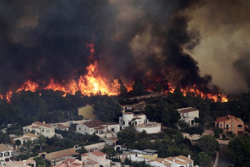
July 2020, firefighters spent days battling a raging fire aboard the 843-foot-long assault ship USS
2CHAPTER 1. INTRODUCTION
Figure 1.1: Wildfires at the WUI can cause widespread human loss and immense destruction
Bonhomme Richard, which was undergoing refit in San Diego’s Naval Base. The blaze raged for four
days. And when it was over, the ship had suffered damage to 11 of her 14 decks. In November 2020,
it was announced that between the fire itself and the days-long firefighting effort, about 60-percent of
the ship was ruined and would have had to be rebuilt or replaced, at a cost between $2.5 billion and
$3.2 billion and taken five to seven years hence, sadly, the Navy decided to scrap the only 22-year
old USS Bonhomme Richard (US Naval Institute News) [19, 20].
All firefighters were withdrawn from the ship by authorities for safety reasons and they had
to battle the raging fires by remote approaches, including water dropped from the buckets attached to
the helicopters or delivered into the ship by hoses from firefighting boats surrounding it on the bay,
see Figure 1.2. The hundreds of thousands of gallons of water pumped to fight the blazes caused
water damage, in addition to fire damage, and as a result, the ship “significantly listed to starboard
and then to port”. Moreover, air pollution was prevalent over the San Diego metropolitan area during
those days.
While this fire was eventually brought under control, in all likelihood it could have been
expediently extinguished with liquid nitrogen, instead of water, and the fire destruction to the ship
and the associated air pollution would have been minimized. Moreover, the water damage would
3CHAPTER 1. INTRODUCTION
Figure 1.2: Firefighters spent four days battling a raging fire aboard the Bonhomme Richard warship,
spraying water to lower decks from side openings
have been entirely avoided. Similarly, the extinction of other challenging fires in industries, refineries,
warehouses, buildings can benefit from the application of liquid nitrogen. All it requires is the
evacuation of living beings before its application to avoid the suffocation and frostbite. Often the
application of water by fire-fighting hose causes damage that is worse than the damage by the fire
itself. In the case of Bonhomme Richard, the ship ended up listing perilously. Both the listing and
the water damage would have been avoided if liquid nitrogen were used instead of water. Liquid
nitrogen is also safer than chemical fire extinguishing foams, as those cause atmospheric pollution as
well as groundwater and/or seawater contamination.
1.2 Background and Previous Work
Liquid nitrogen (LN2) is produced industrially by fractional distillation of liquid air. Its
boiling point is 77 K [21]. The retail cost of liquid nitrogen is in the order of $1/Liter. Because of
its special cooling characteristics, it is widely used in biology, medical treatment, food, metallurgy,
electronics, aerospace, and other cryogenic industry fields [22]. When it is employed as a fire
4CHAPTER 1. INTRODUCTION
suppressant, it can expediently cool down the temperature around the fire. In addition, the application
process is accompanied by abrupt evaporation and expansion which can facilitate the extinguishment
because the air is expelled from the fire. However, it still has several disadvantageous properties such
as high volatility when compared to water which may make it rather difficult to reach the core of the
fire from a distance and quench the combustion. The thermophysical properties of liquid nitrogen are
distinct when compared to water, see Table 1.1 and Figure 1.3.
Table 1.1: Thermophysical properties of water and liquid nitrogen
Latent heat
Vapor Liquid Surface Dynamic Boiling
of
density density tension viscosity point
evaporation
(kg/m3 ) (kg/m3 ) (mN/m) (mPa·s) (K)
(kJ/kg)
Water 0.59 810 72 1 2,260 373
LN2 1.16 997 8.94 5.5 199 77
5CHAPTER 1. INTRODUCTION
Figure 1.3: P-T diagram of the nitrogen
For liquid nitrogen, its latent heat of evaporation and boiling point are much smaller than
the corresponding properties of water which means it can expand more quickly and abruptly to
hundreds of times of its original volume. According to the work done by Levendis et al. [23], it is
confirmed that direct application of liquid nitrogen on a pool fire leads to immediate evaporation to
gaseous nitrogen at 77 K. A rapid expansion of 175 times at 77 K is produced subsequently and if
the temperature of the gaseous phase keeps increasing due to the higher temperature of the flame,
more than 1,000 times of expansion can be easily achieved [23]. Because of such different physical
properties, the LN2 jet is expected to behave differently than the water jet. Atomization of cryogenic
fluids is complex owing to both mechanical jet breakup and flash evaporation [24]. The distinct
thermophysical properties of LN2 can cause peculiar spray features when compared to water, the
spray features of both water and liquid nitrogen have been broadly investigated [25–28].
Previous work has shown the effectiveness of LN2 as a fire suppressant to extinguish the
pool fire [22, 23]. According to the results of both small-scale and large-scale experiments done by
6CHAPTER 1. INTRODUCTION
Levendis, Delichatsios and co-workers [23], a small quantity of LN2 was straightly poured into the
pool fire with various types of fuels. The experiments revealed that abrupt evaporation and expansion
occured as soon as LN2 reached the surface of the burning fuel and fire was extinguished almost
instantaneously after nitrogen vapor fully covered the fire. It was then concluded that 0.5 L of liquid
nitrogen were adequate to quench a 1 m2 of pool fire [23].
According to Shi and Zhou’s work [22], instead of direct dumping LN2 onto the pool fire,
an LN2 direct jet system was developed to blanket the pool fire with oil and the effects of LN2 flow
rate (ranging from 1.13 LPM to 4.11 LPM), pipe diameter (0.01 m, 0.02 m, and 0.04 m) and release
distance (0.25 m, 0.5 m, 0.75 m, and 1 m) were analyzed. When the liquid nitrogen release distance
was set at 0.50 m and the pipe diameter was 0.04 m, fire extinguishing time was the shortest at 1.6 s.
In general, adequate experimental results have proved the effectiveness of LN2 as an ideal
fire suppressant under certain circumstances when compared to water.
1.3 Research Objective and Overview
In this thesis, first objective is to conduct small-scale laboratory experiments to compare
the effectiveness of LN2 and water jets to extinguish fires in an enclosure. Another objective is to
establish and validate a preliminary model for simulating the evaporation rate of the vertically falling
LN2 droplets. The last objective aims to establish the momentum and evaporation models of the
LN2 droplets during the secondary atomization domain and analyze the effects of droplet size, initial
velocity and injection angle on the droplet trajectory and evaporation rate under a certain temperature
distribution profile.
Chapter 1 shows the severity and the aftermath of wildfires around the globe and demon-
7CHAPTER 1. INTRODUCTION
strates the great potential of using liquid nitrogen as an effective and environmental benign fire
suppressant.
Chapter 2 initially presents facilities and procedures of the small-scale experiment (see
Section 2.1). Then, the effectiveness and feasibility of using liquid nitrogen to extinguish the fire in a
partially closed domain (see Section 2.2) are discussed.
Chapter 3 originally introduces the concept of the “one-hour fuel” and the safety operation
distance when tackling this type of fire. (see Section 3.1). Next, the mechanism of the liquid jet
breakup is mentioned and the breakup length of a liquid jet and its potential effect are discussed.
(see Section 3.2). Finally, a simplified model is established to numerically simulate the motion and
evaporation of the LN2 droplets when traveling in a heated environment (see Section 3.3 and 3.4).
Chapter 4 illustrates the simulation results and analyzes the effects of the droplet size,
initial velocity and injection angle on the droplet trajectory and evaporation rate under a certain
temperature distribution profile (see Section 4.2).
Chapter 5 concludes the thesis and gives the overall recommendations.
Chapter 6 discusses the future work on the breakup and flashing mechanisms of liquid
nitrogen jet, as well as the new methods of liquid nitrogen delivery.
8Chapter 2
Small-Scale Experiments and Results
2.1 Experiment Facility and Procedure
Several preliminary experiments were carried out to validate the feasibility and examine
the performance of using LN2 as a suppressant when tackling the fire in a partial enclosure. The
experimental settings are shown in Figure 2.1. Several thick 7-cm long matches were placed upright
inside a metallic basket and an aluminum lid was placed on the top to cover half of the opening.
This arrangement was made to create an accessible enclosure around the matches. This experiment
addressed enclosure fires, in an effort to simulate the fire that took place in the space of the lower
decks of the aforesaid Bonhomme Richard warship. Liquid nitrogen or water was poured into a
plastic syringe (with the needle removed). The syringe was placed directly above the opening of the
bucket, a quarter of a meter higher than the location of the matches. The matches were lit and were
allowed to burn for several seconds, to generate a relatively steady strong fire, before the liquid fire
extinguisher was allowed to escape from the syringe. The jet of the liquid exiting the syringe was
either directed to the burning matches or it was blindly aimed at any random point inside the bucket.
9CHAPTER 2. SMALL-SCALE EXPERIMENTS AND RESULTS
Figure 2.1: Experimental setting for simulating the fires in an enclosure
2.2 Experiment Results and Discussion
The experiment results are shown in Figure 2.2 from Case a to Case c. The following
observations were made:
1. Blind application of the water jet in the enclosure was totally ineffective. The fire burned
on and it extinguished only when the wooden matches were consumed by the fire (see Case a).
2. Direct application of the water jet on the fire did not fare much better either, as only the
fire on the wetted match was extinguished, where the adjacent ones kept burning (see Case c).
3. On the contrary, when liquid nitrogen was applied, violent evaporation occurred once
the liquid hit the basket bottom. The cold nitrogen gas then quickly expanded and snuffed all the
fires expediently and effectively within 5 s (see Cases b and d).
4. Moreover, the cold cloud of gaseous nitrogen filled the enclosure for a considerable
10CHAPTER 2. SMALL-SCALE EXPERIMENTS AND RESULTS
period of time, preventing the possibility of re-ignition.
Overall, from the experimental result, we can conclude that the use of liquid nitrogen as
a fire suppressant in a partially closed region is feasible and more effective when compared with
water. Under some special firefighting situation such as the fire at the lower deck of the Bonhomme
Richard warship, water was blindly injected into the burning region from the side openings, and
it has been proven as ineffective. On the contrary, according to the experimental result, the liquid
nitrogen can be employed remotely without precise aiming and should quench the fire because the
expanded nitrogen gas can expediently fill the targeted area and snuff the fire.
11CHAPTER 2. SMALL-SCALE EXPERIMENTS AND RESULTS
a) Blind (without aiming) spray of water:
b) Blind (without aiming) spray of liquid nitrogen:
c) Directed spray of liquid nitrogen:
d) Directed spray of water:
Figure 2.2: Laboratory experiments in a small home-made exposure. A small jet of water or liquid
nitrogen was used to extinguish fires of 5 matches. The jet was either aimed blindly at a random
point inside the enclosure (Cases a and b), or it was targeted directly on the matches (Cases c and d)
12Chapter 3
Theory
In this section, a simplified mathematical model is established to investigate the feasibility
of using LN2 as a fire suppressant when tackling a hypothetical small “one-hour fuel” fire. In this
thesis, the concept of the “one-hour fuel” is defined as a type of fuel mainly consists of timber
litter or logging slash which can keep burning for 1 hour. The fire is supposedly tackled by a
truck/hose/nozzle approach. Generally, a liquid jet is a multi-phase flow; it evolves from an initial
liquid jet phase to a totally dispersed phase when experiencing primary mechanical breakup due to
shear force and secondary atomization. We assume here that flash evaporation does not occur when
the pressure at the exit of the nozzle in no more than twice the atmospheric pressure. Eventually, it
forms a spray containing poly-dispersed drops. The objective is to examine if those LN2 droplets
could survive after the primary jet breakup and travel to the fire core without getting fully evaporated.
13CHAPTER 3. THEORY
3.1 One-Hour Fuel and Safety Operation Distance
One-hour fuel is introduced to make predictions on the performance of LN2 droplets. Its
diameter is set to be 3 m (10 ft) and according to the data in Ref. [29], the flame height of the
one-hour fuel is taken as 2 ft and the diameter of the flame is assumed to be 3.38 m. Meanwhile,
owing to the high heat flux released from the burning fuel, fire suppression needs to be operated
beyond a certain safety distance. According to the work of Nolan [30], several thresholds of heat
fluxes are provided [18]:
(i) 37.8 kW/m2 can cause major damage to a process plant and storage tank equipment.
(ii) 12.6 kW/m2 may start secondary fires.
(iii) 4.7 kW/m2 can cause pain on exposed skin.
So, 4 kW/m2 is used as a safe heat flux for a firefighter which is lower than all the threshold
values mentioned above [18]. Based on the average flame height formula given by Heskestad [31]:
Lf = 0.23Q̇2/5 − 1.02Dp (3.1)
Where Lf is the flame height, Q̇ is the heat release rate (HRR) of the fire in kW and Dp is
the pool diameter in m.
The heat release rate (HRR) of the one-hour fuel is calculated as 1053 kW. Considering
the fire as a point source and according to the inverse square law, the heat flux equation is [18]:
Xr Q̇
q̇ 00 = (3.2)
4πR2
Where q̇ is the heat flux in kW/m2 , Xr is the radiant fraction and is taken as 0.36 for this
case.
14CHAPTER 3. THEORY
The safety operation distance when tackling this one-hour fuel fire can then be expressed
as [18]:
s
Xr Q̇
R= (3.3)
4π q̇ 00
Substituting the corresponding values into Eq. (3.3), the safety operation distance is
calculated as 2.75 m from the center of the fire.
3.2 Mechanical Breakup and Breakup Length of a Liquid Jet
When a liquid jet is injected from a nozzle into the quiescent atmosphere, it experiences
two stages of breakup: primary breakup and secondary atomization. Primary break up occurs due
to the effect of shear acting on the jet surface and it results in the ligaments separation. After the
primary breakup, the ligaments continue to move at a relative velocity to the ambient air and smaller
fragments are stripped away from the ligaments because of the effect of both surface tension and
shear. During this process, the ligaments undergo additional breakup to a large number of droplets
when critical Weber number (We) is achieved [32]. This process is called secondary atomization, see
Figure 3.1 for the schematic of primary breakup and secondary atomization [24].
Weber number (We) is a dimensionless number which can be used to describe the multi-
phase flow and it takes the form of:
ρl v 2 d
We = (3.4)
σ
When liquid nitrogen is used to extinguish the fire, the jet length is a vital element because
longer jet length can help extend the operation distance. According to a report from K.A. Sallam
15CHAPTER 3. THEORY
Figure 3.1: Schematic diagram of primary breakup and secondary atomization [24]
[25], the jet breakup length is related to Weber number when Weber number is low (i.e., We <
10,000). After a critical Weber number (i.e., We = 30,000) is achieved, the jet breakup length becomes
independent of the Weber number and can be described as [25]:
Lx /d = 11.0 (ρl /ρf )1/2 (3.5)
A shadowgraph near the tip of a turbulent round water jet at a large Weber number is shown
in Figure 3.2 [25]. From Figure 3.2, the ligaments are stripped away from the liquid core and more
tiny droplets are dispersed around the ligaments and jet core.
Next, for the liquid nitrogen jet, assume the velocity of the jet at the nozzle exit is 10 m/s,
the nozzle diameter is 1.9 cm, the ambient temperature is at 20°C and atmospheric pressure is at 1
atm. The surface tension of liquid nitrogen at its saturation temperature (77 K) is 8.94 mN/m. The
density of air and liquid nitrogen are 1.2 kg/m3 and 810 kg/m3 , respectively. The corresponding
Weber number is over 170,000 which is much larger than 30,000. The calculated jet breakup length is
around 5.4 m after substituting each term into Eq. (3.5). However, flash evaporation arises when there
exists a sudden pressure drop between the pipe and nozzle exit. Bubbles are generated inside the jet
16CHAPTER 3. THEORY
core and the bursts of the bubbles facilitate the secondary atomization which result in the reduction
of the jet breakup length. Also, when liquid nitrogen is released in a heated environment, high
ambient temperature also performs a negative impact on the breakup length. The calculated breakup
length may be reduced based on those factors. In general, the jet breakup length is a beneficial and
noteworthy element when using liquid nitrogen jet as a fire suppressant since it can further extend
the operation distance and protect the lives of firefighters.
Figure 3.2: The Shadowgraph near the tip of a turbulent water jet in quiescent air (We = 33,100, d =
4.8 mm, at a distance of 1,040 mm from the jet exit) [25]
17CHAPTER 3. THEORY
3.3 Preliminary Model Formulation and Validation
3.3.1 Preliminary Model of a Vertically Falling Spherical Droplet
A simplified model is firstly established for a vertically falling LN2 droplet aiming to
predict the trajectory of droplets after the primary jet breakup and their mass loss due to evaporation
when approaching the fire. Based on the work of C.H. Cheng and Y. Ruan [26–28, 33], several
assumptions are made in the model:
a) The droplet is considered as a sphere falling due to gravity;
b) The droplet falls freely and only the velocity gradient along y-direction is considered;
c) For the evaporation of LN2 droplet, it is assumed that no thermal radiation is involved,
and that heat is only transferred through convection. The heat from surrounding gas is used for
evaporation and the droplet surface temperature and density remain constant [26];
d) The droplet moves in static air without any airflow disturbance.
When a spherical droplet falls vertically in the static air, several forces are introduced
to describe its motion: the gravitational force, the drag force, and the buoyancy force acting on
the droplet. In addition to those forces, another force related to the droplet momentum loss due to
evaporation is also brought into the model. The dominant equation that describes the droplet motion
is:
d~
p
= F~ (3.6)
dt
Where p~ = m~v is the droplet momentum, m is the droplet mass, ~v is the droplet velocity
and F~ is the total force acting on the droplet.
18CHAPTER 3. THEORY
Making the downward direction as the positive y-direction, and substituting total force
into the combination of the gravitational force, the drag force and the buoyancy force, then Eq. (3.6)
becomes:
dp dmv dm dv
= =v +m = Fg − Fd − Fe − Fb (3.7)
dt dt dt dt
Where Fg , Fd and Fb are the gravity force, drag force and the buoyancy force acting on
the droplet, Fe is the force responsible for the momentum loss due to evaporation.
Meanwhile, for the momentum loss due to evaporation, Fe can be described as:
dm
v = −Fe (3.8)
dt
The gravity force, drag force and buoyancy force can be expressed as:
4π
Fb = ρf gR3 (3.9)
3
1
Fd = Cd ρf v 2 πR2 (3.10)
2
4π
Fg = ρp gR3 (3.11)
3
The expression of the drag coefficient is shown in Eq. (3.11) since it has been modified to
improve the accuracy under low-Re conditions [34]:
3808 (1617933/2030) + (178861/1063) Re +(1219/1084) Re2
CD = (3.12)
681 Re (77531/422) + (13529/976) Re −(1/71154) Re2
19CHAPTER 3. THEORY
The equation of a vertically falling droplet motion takes the form of:
dv ρf 3Cd ρf 2
= 1− g− v (3.13)
dt ρp 4D ρp
The evaporation rate of the LN2 droplet can be found in the report of Y. Ruan [26]:
1 1
dD 4kg Cpg (T∞ − Tp )
=− 3
1 + 0.3(Pr) (2 Re) 2 ln 1 + (3.14)
dt ρp · Cpg · D hfg
Then, the Runge-Kutta method is employed to numerically solve the coupled ODEs in Eq.
(3.13) and (3.14). All results are obtained by using the ODE45 solver in MATLAB® and the time
step is set to be 0.001s to maintain both computing accuracy and performance.
3.3.2 Model Validation
The model is then validated against the experimental data of Awonorin [35] who conducted
experiments where liquid nitrogen droplets fell freely in static air kept at a constant temperature
of 30°C. The droplet size and corresponding falling distance were measured according to enlarged
prints of each frame shot by the high-speed cinecamera. In the simulation, the initial LN2 droplet
diameter and air temperature are set at 2 mm and 30°C, respectively. The comparison of simulation
results and experimental data is shown in Figure 3.3.
Figure 3.3 shows that the overall trends of the simulation curve and the fitted curve are the
same. Also, both curves gradually converge and the maximum error between experimental data and
simulation is 0.01 mm which is acceptable; thus, it is safe to say this model can be used to simulate
the LN2 droplet evaporation.
20CHAPTER 3. THEORY
Figure 3.3: The comparison of simulation results and experimental data from Awonorin [35]
3.4 Droplet Evaporation Model After Primary Jet Breakup
In this section, the model is further modified to simulate the motion of an evaporating LN2
droplet in both x and y directions after the jet breakup. In this model, the jet breakup length is not
considered, and this model only focused on the droplets formed during the secondary atomization
domain.
The LN2 droplet in this section is assumed to be an evaporating liquid nitrogen sphere with
an initial droplet velocity. Velocities along both x and y directions are considered when calculating
the droplet properties and make the positive x-direction from left to right and the positive y-direction
to be downward. Then, the equation of the droplets motion becomes:
21CHAPTER 3. THEORY
dpx dmvx dmx dvx
= = vx +m = −Fdx − Fex
dt dt dt dt (3.15)
dpy = dmvy = vy dmy + m dvy = Fg − Fdy − Fey − Fb
dt dt dt dt
The components of Fd and Fe can be expressed as:
dm dm Fd vx Fd vy
vx = −Fex , vy = −Fey , Fdx = , Fdy =
dt dt v v
Also, the droplet velocity can be further described as:
q
v= vx2 + vy2
Substituting corresponding terms in the motion equations and rearranging, a model that
describes the motion of LN2 droplets, considering both evaporation and air resistance becomes:
dvx 3Cd ρf q 2
vx vx + vy2 = 0
+
dt 4D ρp
dvy 3Cd ρf q 2 ρf
2
+ vy vx + vy = 1 − g
dt 4D ρp ρp
dx
= vx (3.16)
dt
dy
= vy
dt
1 1
dD 4kg Cpg (T∞ − Tp )
=− 3 2
1 + 0.3(Pr) (2 Re) ln 1 +
dt ρp · Cpg · D hfg
The Runge-Kutta method is used to solve Eq. (3.16); it is imported into MATLAB® and
solved numerically by utilizing the embedded ODE45 Solver. The time step is set to be 0.001 s to
ensure both computing accuracy and performance. The droplet is released at 1.5 meters above the
ground level. The computation is terminated either when the droplet fell to the ground (i.e., 1.5 m
vertically) or when its diameter becomes zero.
22CHAPTER 3. THEORY
The simulation results for different cases and corresponding analysis are given in the next
section based on this model.
23Chapter 4
Simulation Results and Analysis
4.1 Baseline Cases of LN2 Droplet Motion and Evaporation
Baseline case is firstly set to investigate some properties of the LN2 droplets during
falling on its velocity and trajectory, at a fixed air temperature. For this case, the initial droplet
diameter is 2 mm, the air temperature is kept constant at 150°C, initial horizontal velocity is 10
m/s and initial velocity along y-direction is 0 m/s. The corresponding constants are listed below:
Cpg = 1.046 kJ/K, µg = 2.315×10⁻⁵ Pa·s, kg = 34.3 mW/m·K, υa = 2.905×10⁻⁵ m2 /s, ρp =
810 kg/m3 , ρf = 0.834 kg/m3 , T∞ = 423 K, Tp = 77 K, hfg = 199 kJ/kg.
The velocity profiles along x and y directions are shown in Figure 4.1(a) and Figure 4.1(b),
the droplets trajectory profile and the droplets diameter change with respect to time can be found in
Figure 4.2(a) and Figure 4.2(b).
According to the results shown in Figure 4.1 and Figure 4.2, the velocity along x-direction
drops sharply due to the effect of drag force and gravity at the early stage. But, due to the continuous
evaporation, the deceleration is weakened because the velocity and diameter keep decreasing before
24CHAPTER 4. SIMULATION RESULTS AND ANALYSIS
(a) Droplet velocity profile along x-direction (b) Droplet velocity profile along y-direction
Figure 4.1: Droplet velocity profiles along x and y directions. The air temperature is 150°C and
initial horizontal velocity is 10 m/s
(a) Droplet trajectory profile (b) Droplet diameter profile
Figure 4.2: Trajectory and diameter profiles of 2-mm LN2 droplets. The air temperature is 150°C
and initial horizontal velocity is 10 m/s
25CHAPTER 4. SIMULATION RESULTS AND ANALYSIS
the droplets hit the ground and the final velocity along x and y direction are about 3 m/s and 3.6
m/s when time is 0.64 s. Regarding the droplet trajectory, the droplet is predicted to travel over
3.5 m when air temperature is 150°C. Figure 4.2(b) also indicates that the droplet diameter when
it reaches the ground level is more than 1.3 mm which means it still retains 30 % of its original
volume. Considering the high volatility of the LN2 and the high surrounding temperature (150°C),
this amount of remaining liquid volume is still considerable.
Subsequently, the effects of surrounding temperature on the LN2 droplet trajectory and
evaporation are analyzed by changing the ambient air temperature. The air temperatures are kept
constant at 50°C, 100°C, 150°C and 200°C. The initial droplet diameter and horizontal velocity are 2
mm and 10 m/s, respectively. The droplet trajectory profile and diameter change with respect to time
are shown in Figure 4.3(a) and Figure 4.3(b), respectively.
(a) Droplet trajectory profile (b) Droplet diameter profile
Figure 4.3: Trajectory and diameter profiles of 2-mm LN2 droplets under various air temperatures
26CHAPTER 4. SIMULATION RESULTS AND ANALYSIS
As shown in Figure 4.3, the horizontal flight distance and evaporation rate are affected
by temperature. According to Figure 4.3(a), when surrounding temperature increased from 50°C to
200°C, the droplet travel distance is extended from 3.6 m to 3.9 m instead of falling to the ground
due to higher air temperature. The reason for this increase is due to lower air density at higher
temperatures, the drag force acting on the droplet then decreases and causes the droplet travel further.
However, higher air temperature significantly aggravates the droplet evaporation, the final droplet
diameter at 200°C, when droplet hit the ground, is 1.4 mm which is the lowest value among all cases.
So, the surrounding temperature is one of the most vital elements that decides the longevity of the
droplet.
4.2 Performance of the LN2 Droplet When tackling the One-Hour
Fuel Fire
4.2.1 Effect of Droplet Type and Size on the Flight Distance and Evaporation
In this section, comparisons are made between water and LN2 droplets with different sizes
to investigate the distinct performance characteristics of those types of droplets when tackling the
one-hour fuel fire. To acquire an accurate simulation result, a temperature distribution profile is
needed. Due to the lack of air temperature measurements around the one-hour fuel fires, several
assumptions are made to help build a linear air temperature profile for this section:
a) Assume both linear and parabolic air temperature distribution along x-direction and no
temperature gradient along y-direction.
b) Assume the ambient air temperature remains constant after droplets penetrate the fire
27CHAPTER 4. SIMULATION RESULTS AND ANALYSIS
edge.
c) Assume the surrounding pressure is kept constant as 1 atm.
d) Assume the LN2 jet is released at 1.5 meters above the ground.
e) According to the safety operation distance mentioned in the previous chapter, the
firefighters need to be at least 2.75 m from the fire. So, in the section, assume the jet breaks up into
droplets 3 meters away from the fire edge which is larger than the minimum safety distance (2.75
m). Meanwhile, the air temperature T (x = 0 m) and T (x = 3 m) are set to be 320 K and 1,000 K,
respectively.
A simple schematic diagram of position of the droplets and the flame shape is depicted in
Figure 4.4 to help understand the basic idea of this model:
Figure 4.4: Schematic diagram of the position of the droplets and the flame shape
Two different hypothetical air temperature profiles near the one-hour fuel fire are shown in
Figure 4.5.
28CHAPTER 4. SIMULATION RESULTS AND ANALYSIS
Figure 4.5: Hypothetical air temperature distribution profiles (linear and parabolic) near the
one-hour fuel fire
Boundary conditions of both water and LN2 droplets are listed in Table 4.1, the diameter
set is chosen as 1 mm, 2 mm and 3 mm and the initial velocity is 10 m/s for both cases.
Table 4.1: Boundary conditions to investigate the effect of droplet type and size
Droplet type Nozzle diameter Flowrate Initial droplet diameter Initial droplet velocity
1 mm
Water
1.9 cm 170 LPM 2 mm 10 m/s
LN2
3 mm
29CHAPTER 4. SIMULATION RESULTS AND ANALYSIS
(a) Droplets trajectory profile (b) Droplets diameter profile
Figure 4.6: Trajectory and diameter profiles of water and LN2 droplets under linear temperature
distribution
(a) Percentage of remaining mass of LN2 droplets (b) Percentage of remaining mass of water droplets
Figure 4.7: Percentage of remaining mass of LN2 and water droplets when approaching the fire
under linear temperature distribution
30CHAPTER 4. SIMULATION RESULTS AND ANALYSIS
Then, by importing the boundary conditions listed in Table 4.1 into MATLAB®, the
simulation results of the trajectory of both types of droplets and their diameter changes with respect
to time under linear temperature distribution are shown in Figure 4.6(a) and Figure 4.6(b). The
percentages of remaining mass of LN2 and water droplets when approaching fire under linear
temperature distribution are shown in Figure 4.7 (a) and (b).
As we can see from Figure 4.6, in the case of LN2, 2 mm and 3 mm droplets are predicted
to successfully reach the fire domain and penetrate until reaching the fuel surface itself. The 1 mm
droplets do not reach the fire edge, as they fully evaporate at 2 m after 0.5 s. The 2 mm and 3
mm droplets reach the fire and penetrated until hitting the ground level with diameters of 1.17 mm
and 2.40 mm, respectively. For water droplets, all three sizes of droplets can reach the fire edge
with over 66% of their mass, see Figure 4.7(b). All three sizes of water droplets can successfully
penetrate through the fire and hit the fuel surface. The final diameters are 0.87 mm, 1.90 mm, and
2.92 mm, respectively. The remaining mass for the LN2 droplets is smaller due to its high volatility.
However, for a 3 mm LN2 droplet, it could still keep 50% of its initial mass, see Figure 4.7(a),
which emphasizes the necessity of large droplet size. This calculation indicates, as expected, that by
comparison to water, larger droplets of LN2 are needed for reaching the fire. Moreover, the droplet
with a larger size can travel further according to Figure 4.6 and it is because a larger droplet has more
kinetic energy or momentum. Hence, ensuring a certain coarseness of atomization is essential in
this application because the LN2 droplet can reach a further distance and maintain more of its mass
before hitting the fire core. It means that a large orifice diameter is very important.
31CHAPTER 4. SIMULATION RESULTS AND ANALYSIS
In addition to the linear temperature profile, as mentioned above, a parabolic temperature
profile is introduced to examine the potential effect of different temperature patterns. The initial
droplet diameters are set to be 2 mm and 3 mm. The initial droplet velocity is 10 m/s. The trajectory
of LN2 droplets and the diameter change with respect to time under parabolic and linear temperature
distribution are shown in Figure 4.8(a) and Figure 4.8(b).
(a) Droplets trajectory profile (b) Droplets diameter profile
Figure 4.8: Trajectory and diameter profiles of 2-mm and 3-mm LN2 droplets under different
temperature distribution patterns
As shown in Figure 4.8, the parabolic temperature distribution can slightly extend the flight
distance when it is compared with the linear distribution. Meanwhile, the final diameter of 2 mm
LN2 droplets when reaching the fuel surface is increased from 1.17 mm to 1.23 mm. For 3 mm LN2
droplets, the final diameter is increased from 2.39 mm to 2.42 mm. According to Figure 4.5, ambient
air temperature in the parabolic profile from x = 0 m to x = 3 m is always lower than that in the linear
profile. The reason for the relatively further flight distance and the smaller evaporation rate is due to
the lower temperature in the parabolic temperature profile. It is confirmed that if the air temperature
32CHAPTER 4. SIMULATION RESULTS AND ANALYSIS
profile is a concave-upward parabola, it can result in a further flight distance as well as a greater final
diameter when a droplet reaches the fuel surface.
4.2.2 Effect of LN2 Droplet Initial Velocity on the Flight Distance and Evaporation
In this section, the effect of the LN2 droplet initial velocity is investigated by using
different initial velocity values. The boundary conditions are listed in Table 4.2. The initial horizontal
velocities are set to be 5 m/s, 10m/s, and 15m/s for an LN2 droplet, and it is assumed that the initial
velocity along the y-direction is negligible. The linear temperature profile is considered, and the
initial droplet diameter is 2 mm for this case.
Table 4.2: Boundary conditions of LN2 droplets to investigate the effect of the initial velocity
Droplets type Initial droplet diameter Initial droplet velocity Nozzle diameter Flowrate
5 m/s 85 LPM
LN2 2 mm 10 m/s 1.9 cm 170 LPM
15 m/s 255 LPM
The simulation results are shown in Figure 4.9(a) and Figure 4.9(b):
33CHAPTER 4. SIMULATION RESULTS AND ANALYSIS
(a) Droplets trajectory profile (b) Droplets diameter profile
Figure 4.9: Trajectory and diameter profiles of the 2-mm LN2 droplets with various initial velocities
As shown in Figure 4.9, the horizontal flight distance of the LN2 droplet is significantly
impacted by the initial droplet velocity. The flight distance increases as the initial velocity climbed
up. A droplet with a velocity at 5 m/s cannot reach the fire. It hits the ground after about 0.6 s with a
2.2 m flight distance. For the droplets with an initial velocity at 15 m/s, the flight distance is over 5.2
m which is larger than that with 10 m/s initial velocity. It indicates that higher initial velocity enables
the LN2 droplet with the same size to travel further because of greater initial momentum. On the
other hand, the final diameter of the droplet with 15 m/s velocity is the smallest (0.96 mm) among all
three cases because of its longest airborne time (0.68 s). In general, the higher initial velocity can
extend the valid droplet spray range which allows firefighters to operate at bigger distances from the
fire. Meanwhile, droplet velocity should also be large enough to provide the necessary momentum
for the droplet to reach the designated fire domain. Again, the basic criterion of using LN2 as a fire
suppressant is that the LN2 droplets should maintain significant volume when they reach the fire core.
34CHAPTER 4. SIMULATION RESULTS AND ANALYSIS
Based on this criterion, droplet velocity restriction is also required because lengthier flight distance
means longer airborne time. This may enlarge the droplet exposure to the hot air and intensify the
droplet evaporation.
4.2.3 Effect of LN2 Droplet Injection Angle on the Flight Distance and Evaporation
During the actual operation of fire suppression, the velocity cannot be increased to reach
a farther distance when the maximum flow rate is achieved. So, the nozzle should be held at an
appropriate angle. In this section, the initial condition of droplet velocity is slightly adjusted to
examine the impact of droplet injection angle on the flight distance and evaporation, see Table 4.3.
Let the injection angle be θ and the initial velocities along x and y direction become:
vx = V0 cos θ
(4.1)
vy = V0 sin θ
Where V0 is the initial droplet velocity after the primary breakup, vx and vy are the initial velocity
components along x and y directions. The initial conditions of this case are listed in Table 4.3, the
positive velocity along x and y directions are from left to right and from top to bottom, respectively.
35CHAPTER 4. SIMULATION RESULTS AND ANALYSIS
Table 4.3: Boundary conditions of LN2 droplets to investigate the effect of injection angle
Initial
Initial
Injection Nozzle droplet
droplet Flowrate vx vy
angle diameter velocity
diameter
V0
-15° 9.66 m/s 2.59 m/s
15° 9.66 m/s -2.59 m/s
0° 1.9 cm 10 m/s 2 mm 170 LPM 10 m/s 0 m/s
30° 8.66 m/s -5 m/s
45° 7.07 m/s -7.07 m/s
The simulation results are shown in Figure 4.10(a) and Figure 4.10(b).
(a) Droplets trajectory profile (b) Droplets diameter profile
Figure 4.10: Trajectory and diameter profiles of the 2-mm LN2 droplets with various injection angles
36CHAPTER 4. SIMULATION RESULTS AND ANALYSIS
From Figure 4.10, droplets with a positive injection angle start to ascend due to the velocity
component of the y-direction. During the ascension process, the droplets gradually decelerate due to
the effects of drag force and gravity until they reach the peak. Similarly to the effect of the initial
velocity on the flight distance, the droplets typically fly further with an appropriate injection angle.
The flight distance of droplets with 15°, 30°, or 45° injection angle can travel at least 4.1 m which is
slightly further than that with 0° injection angle. The greatest flight distance (4.6 m) among all cases
is achieved when the injection angle is 15°. The final diameter of the droplets is 0.68 mm which
is less than that with 0° injection angle. Droplets with 45° injection angle fully evaporate without
arriving at the fire. For a droplet with a 30° injection angle, it can successfully reach the fire edge
with 0.35 mm of diameter left, however, it disappears when approaching the fuel surface. For the
case with -15° injection angle, the droplet cannot reach the fire edge but hits the ground at 2.9 m
with 1.54 mm of its diameter left. However, if the injection angle is increased from 30° to 45°, the
flight distance is reduced from 4.5 m to 4.1 m. It may attribute to the greater momentum loss during
the ascent process. Furthermore, during the ascent stage, for droplets with a certain injection angle,
extra volume is consumed due to evaporation, it then reduces the drag force acting on the droplets
and it might be the reason for a greater flight distance than that with 0° injection angle. Among all
cases shown in the figures above, 2-mm LN2 droplets with 15° injection angle have the greatest
flight distance and could also reach the fuel surface without getting evaporated. Droplets for neither
45° nor 30° cases could reach the fuel surface. Overall, the injection angle affects both the droplet
flight distance and evaporation process, an appropriate injection angle can facilitate the increase
of droplet flight distance which is beneficial to extend the valid operation range for firefighters.
However, too large an injection angle like 45° should be avoided because extra momentum may be
37CHAPTER 4. SIMULATION RESULTS AND ANALYSIS
consumed to overcome the drag and gravity and the evaporation is also amplified simultaneously due
to high-temperature exposure during the ascent stage.
4.2.4 Effect of Thermal Radiation on the Droplet Flight Distance and Evaporation
The heat transferred through thermal radiation is also a factor that needs to be examined
when the droplet approaches the fire. In this section, it is assumed that radiant energy is emitted at the
central point of the one-hour fuel fire. Also, in the following the impact of convection is neglected.
The initial conditions are listed as follows: The horizontal distance between droplet and fire envelope
is 3 m. Droplets are released 1.5 m above the ground. The flame height and diameter are 0.61 m and
3.38 m, respectively. The energy balance is firstly introduced in Eq. (4.2):
dm
Qrad = hfg (4.2)
dt rad
The Qrad can be expressed as:
00 dm
q̇ × A × VF = hfg (4.3)
dt rad
Substituting Qrad in Eq. (4.2) and the energy balance becomes:
00 dm
q̇ × A × VF = hfg (4.4)
dt rad
Then, q̇ 00 is substituted according to Eq. (3.2):
Xr Q̇ dm
× A × VF = hfg (4.5)
4πR2 dt rad
1 ρp πD3
Where A = πD2 , VF = , and m = .
2 6
38CHAPTER 4. SIMULATION RESULTS AND ANALYSIS
Substituting A , VF , and m with the corresponding terms above,
ρp πD3
d
Xr Q̇ 1 6
2
× πD2 × = hfg (4.6)
4πR 2 dt
Rearranging:
dD Xr Q̇
=− (4.7)
dt rad 4πR2 ρp hfg
Where R is defined as the distance from the center of the fire to the droplet. According to
Figure 4.4, it can be expressed as: R = (3 + 3.38/2) − x = (4.69 − x).
Then, add the effect of convection to Eq. (4.7), the model considers both the impacts of
thermal radiation and convection on droplets becomes:
dvx 3Cd ρf q 2
vx vx + vy2 = 0
+
dt 4D ρp
dvy 3Cd ρf q 2 ρf
2
+ vy vx + vy = 1 − g
dt 4D ρp ρp
dx
= vx
dt
dy
= vy
dt
1 1
dD Xr Q̇ 4kg 1 + 0.3(Pr) 3 (2 Re) 2 ln 1 + Cpg (T∞ − Tp )
= −
2
+
dt 4π(4.69 − x) ρp hfg ρp · Cpg · D hfg
(4.8)
39CHAPTER 4. SIMULATION RESULTS AND ANALYSIS
The model is then imported into MATLAB® with the initial conditions listed in Table 4.4:
Table 4.4: Boundary conditions of LN2 droplets to investigate the effect of thermal radiation
Droplet type Nozzle diameter Flowrate Initial droplet diameter Initial droplet velocity
1 mm
LN2 1.9 cm 170 LPM 2 mm 10 m/s
3 mm
For the case of linear air temperature distribution, the simulation results are displayed in
Figure 4.11(a) and Figure 4.11(b):
(a) Droplet trajectory profile (b) Droplet diameter profile
Figure 4.11: Trajectory and diameter profiles of the LN2 droplets under the effects of thermal
radiation and convection
From Figure 4.11, the droplets trajectory and diameter curves when both thermal radiation
and convection are considered almost coincide with those in the case which only the impact of
40CHAPTER 4. SIMULATION RESULTS AND ANALYSIS
convection is included. The flight distance and the final droplet diameter when the droplets settled
at the fuel surface are nearly identical in both cases. Therefore, it can be concluded that the
thermal radiation has an insignificant impact on either the droplet trajectory or its evaporation rate.
According to Ref. [23], the radiation heat transfer from the surface of a pool fire is typically in the
order of 1 W/cm2 , for droplets having radii between 1 mm and 10 cm. Hence, the reason for the
negligible impacts of thermal radiation on droplet motion and evaporation is attributed to the small
cross-sectional area of the drops.
41You can also read