CREATING A TIME SLICING EFFECT - GOPRO ARRAY RIG & WORKFLOW
←
→
Page content transcription
If your browser does not render page correctly, please read the page content below
Creating a Time Slicing Effect –
GoPro Array Rig & Workflow

Prepared for: David Long, Program Chair of BS Motion Picture Science
              Ricardo Figueroa, Assistant Professor of BS Motion Picture Science
              Malcolm Spaull, Administrative Chair of the School of Film and Animation
              Carl Salvaggio, Research Professor in the College of Imaging Science
              Atia Quadri, Assistant Professor in the School of Film and Animation

Prepared by: Michael H. Richos
             Motion Picture Science Undergraduate Student
             Rochester Institute of Technology, School of Film and Animation

May 25, 2014
December 19, 2013***
October 15, 2013**
May 9, 2013*
*Original Proposal Date
**Micro-Grant Proposal Date
***First Semester Update

                                                                  Advisor Signature: Ricardo Figueroa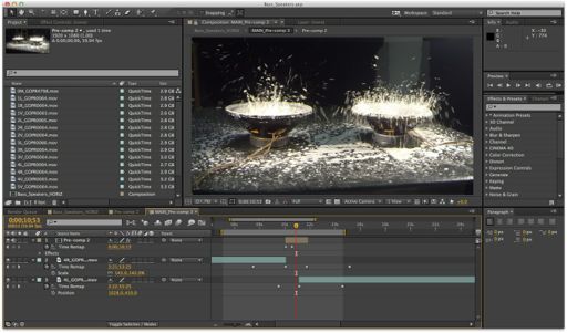
CREATING A TIME SLICING EFFECT – GOPRO ARRAY RIG & WORKFLOW RICHOS | 1
Creating a Time Slicing Effect – GoPro Array
Rig & Workflow (May 2014)
Michael H. Richos, Student, Rochester Institute of Technology
Starting in 2005 with over $350,000 to over $500
Abstract —! Time Slicing or as we may know it as, “Bullet million in 2012. In a market dominated by the
Time” is an effect most famously achieved in The Matrix mobile device and its camera GoPro isn’t just
(1999). The effect is achieved using a series of still cameras surviving, it’s thriving.
surrounding your subject. At the point of action, the cameras
are set off simultaneously to capture that one point in time
from various positions. The Matrix used this technique, but The decision was made to mount multiple GoPro
incorporated a laser targeting system to form a uniform curve Hero 3 cameras on an aluminum crafted, curved bar
in space of a given radius. When triggered, every camera rig. These cameras will be set to capture an object in
would begin to capture the action at a high frame-rate as it motion at a high frame rate and then stitched together
was happening. This footage was then processed to interpolate in post-production. This setup will simulate the
between each camera at one point in time with heavy frame-
to-frame interpolation.
effect of movement around the object while said
object appears fixed, also known as the “Bullet Time
My technique that will be provided for students in the Effect”.
School of Film and Animation at RIT is similar to that of The
Matrix, but will not contain any large amount of intense These cameras are cheap enough, small enough, and
computer interpolation between each image and will rely on a light enough to simulate this effect for student use at
fixed rig of 14 GoPro Hero 3: Black Edition cameras rather the School of Film and Animation at RIT. In
than a laser generated curved path. The difference between
building this rig there are three main goals (and one
my rig array and other similar GoPro arrays is the addition of
an interchangeable curved and straight vertical element, extended goal being attempted) that must be
giving artists a new perspective. This method will create a accomplished for it to be reasonably used by other
few interpolation artifacts when switching between cameras at filmmakers.
a single point in time, but can be fixed using image • Build the GoPro Array Rig.
interpolation algorithms for motion frames with both o The final rig will be modular for easy
standard editing software or user created implimentation.
breakdown and future additions. It will also
The important thing is to create the rig for capture and
provide the workflow (both capture on post-production) so be available for checkout at the RIT SoFA
that the project can be improved on in the future. Cage.
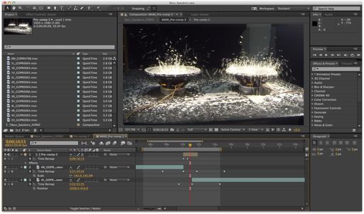
• Provide test footage for a demo reel.
I. INTRODUCTION/OBJECTIVES o The rig will be tested vigorously with
various genres of material. This reel will
T ODAY’S world is infatuated with capturing and demonstrate both proof of concept and give
sharing everything in their life with their family students an understanding of what the rig
and friends. Most of the time these timeless can be used for.
moments are captured with our cell phone cameras. • Create a workflow for SoFA students at RIT to
These All-in-One devices including a high-definition follow step-by-step.
camera are a huge convenience because it takes away o Both a hard and soft copy of the workflow
from having to carry that “one extra device” around. will be provided to checkout at the School of
Film and Animation Cage. This workflow
In 2004 GoPro set out to accomplish the goal of this will include all steps in both production and
“capture and share” method, but by making you the post-production. The production workflow
star. The company wanted to be able to develop a will include how to build and setup the rig
camera system that could go anywhere with you and body as well as how to setup the cameras for
capture the moments that we only relive in our capture. The post-production workflow will
minds. GoPro’s revenue has doubled every year. include how to export the footage and how
to edit the footage in the provided software
templates to achieve the bullet time effect.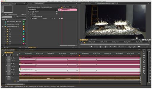
CREATING A TIME SLICING EFFECT – GOPRO ARRAY RIG & WORKFLOW                                                      RICHOS | 2

                                                                average filmmaker doesn’t have the Hollywood budget and
These three objectives (GoPro array rig, test footage for a     time. The completion of this rig will enable students, to
demo reel, and a workflow for students in SoFA at RIT to        continue innovating in SoFA. It will allow filmmakers to
follow step-by-step) are the main goals in the development      test new shots, implement a whole new design workflow,
of this project. If these three goals were to be                and allow these artists to achieve a shot they didn’t see
accomplished ahead of schedule, an extended goal would          possible before at RIT.
be the implementation of image interpolation to achieve a
smoother transition between each of the cameras at a
specific point in time.                                                          II. BACKGROUND/THEORY

This would be achieved using either the method provided
                                                                A. Introduction to Time Slicing Theory
by Ryan Connolly, an RIT Motion Picture Science
Undergraduate Senior in 2013, with his thesis on 3D Multi-
                                                                Time Slicing or as we may know it as, “Bullet Time” is an
view User Interface (May 2013), or the method outlined in
                                                                effect most famously achieved in The Matrix (1999). The
Angel Tamariz Sánchez’ Master Thesis, Interpolation for
                                                                term “Bullet Time” was then registered in 2005 to Warner
Video Navigation (October 2011). Connolly’s method
                                                                Bros. after the success of the film in the video game The
provides users with an image interpolation between two
                                                                Matrix Online. The effect is achieved using a series of still
cameras in a static situation. Personally, I would be more
                                                                cameras surrounding the desired subject. At the point of
inclined to attempt Sánchez’ method for a high quality
                                                                action, the cameras are set off simultaneously to capture
interpolation, but if time is limited, Connolly’s method will
                                                                that one point in time from various positions.
suffice.

                                                                The Matrix used this technique, but incorporated a laser
Sánchez’ method used a “Watershed Algorithm” which
                                                                targeting system to arrange a uniform curve in space of a
essentially picks out and combines sections of pixel code
                                                                given radius. When triggered, every camera would begin
values (sort of like a heat map) with a provided threshold.
                                                                to capture the action at a high frame-rate as it was
When taking the Watershed of both images they can then
                                                                happening. While these cameras were capturing the action
be superimposed onto one another. The first derivative of
                                                                they were also changing position around the laser drawn
the two combined images is determined in Matlab,
                                                                curve. This footage was then processed to interpolate
identifying the images “energy” or general edges. These
                                                                between each camera at one point in time with heavy
edges are used to identify a correlation between the first
                                                                frame-to-frame interpolation. This ensured the bullet time
and second image edges. This correlation is found using
                                                                effect would be smooth and prevent image artifacts when
the “Auction Algorithm”, outlined in Sánchez’ thesis, to
                                                                stepping through cameras.
create the interpolated edges of the new inter-image. The
Auction Algorithm combined with the Watershed
                                                                In addition to these three main project goals, a camera
Algorithm will create an image that can be mapped to the
                                                                characterization was preformed to obtain a better
interpolated edges, section-by-section (rule of thirds) with
                                                                understanding of what the GoPro Hero 3: Black Edition
the combined Watershed sections.
                                                                camera was doing under ideal shooting conditions. Both an
                                                                understanding of what the camera is capable of and not
The technique being provided for the students in the School
                                                                capable of, is important to know before going onto any set.
of Film and Animation (SoFA) at RIT would be similar to
                                                                These tests included Noise, MTF, Dynamic Range/OECF,
that of The Matrix, but will not contain any large amount of
                                                                and Color Reproduction. Each test will be explained
intense computer interpolation between each image and
                                                                further in the experiment’s background and procedure
will rely on a fixed rig of cameras rather than a laser
                                                                section.
generated curved path. This method will create a few
interpolation artifacts when switching between cameras at a
single point in time, but can be fixed using either advance
image interpolation algorithms for motion frames or built-
in frame blending tools in post-production suite software.
The important thing is to create the rig for capture and
provide the workflow so that the project can possibly be
improved on in the future. While the method in The Matrix
in achieving the bullet time effect is the most ideal, the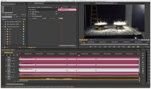
CREATING A TIME SLICING EFFECT – GOPRO ARRAY RIG & WORKFLOW                                                 RICHOS | 3

B. Technical Specifications/Camera Overview                 f2.8, 2.8mm focal length lens. With this known, the
                                                            hyperfocal distance of this system would be about 20-
1) Technical Details/Features (that will be used):          30cm. This means that 20-30cm to infinity would be the
                                                            range of acceptable focus.
     a) 12.40 Megapixel CMOS Sensor 1/2.3"
                                                            The Hero 3 Black Edition has the option to set the field of
     b) Video Resolution: 1920 x 1080 at 60fps              view to 170 degrees (Wide mode, uncropped), 127 degrees
                                                            (Medium mode), and 90 degrees (Narrow mode). The 90-
              (1) Sensor Size: 1/2.3” (6.17 x 4.55) mm      degree “Narrow mode” gives us the easiest FOV to build
                                                            the rig’s design around while also allowing us to add more
              (2) Pixel Size: 1.55um                        cameras in the future without worrying about the cameras
                                                            seeing each other from their crossing FOVs.
     c) ISO: Base 640

     d) Shutter Speed: 1/60                                 C. Rig Build and Design Overview

     e) 4:2:0 Chroma Sub-Sampling                           The idea for a "real world" time slicing effect would only
                                                            be possible if a prototype was able to be made and tested.
     f) Camera Picture Settings                             For this prototype to be feasible, many hours of planning
                                                            took place to make sure that this rig would be as accurate
              (1) GPH3 [ISO 640; WB AUTO; 1/60th;           and precisely made as possible to acquire desirable footage.
                      f/2.8; 1080p 59.94fps]                The design was all contingent on the angle of the bent arm
                                                            and the distance between cameras.
              (2) GPH3 [ISO 640; WB AUTO-Protune;
                      1/60th; f/2.8; 1080p 59.94fps]        A group of second year mechanical engineering students
                                                            from RIT agreed to work with me for both credit and the
              (3) GPH3 [ISO 640; WB 3000K-Protune;          experience. We quickly started to work out the best way to
                      1/60th; f/2.8; 1080p 59.94fps]        go about this from the tools, the material, and the time
                                                            management. It was determined after the first couple of
              (4) GPH3 [ISO 640; WB 5500K-Protune;          meetings that this project was feasible with the tools and
                      1/60th; f/2.8; 1080p 59.94fps]        time available on the RIT campus. As the project began in
                                                            the machine shop, there were continuous adjustments made
              (5) GPH3 [ISO 640; WB 6500K-Protune;          to allow for ease of production and usage for the future
                      1/60th; f/2.8; 1080p 59.94fps]
                                                            users of the rig. There was an active decision made to keep
                                                            extra space on the ends of the bar to allow for
              (6) GPH3 [ISO 640; WB RAW-Protune;
                                                            modifications and future additions to be made.
                      1/60th; f/2.8; 1080p 59.94fps]

                                                            The GoPro Hero 3 Black Edition (GPH3) model is being
     g) Encoding and Decoding Compression Variation
                                                            used because they are currently the only (besides the brand
                                                            new Hero 3+, as of October 2013) models that provide the
              (1) Encode: GoPro Cineform Compression
                      (.mp4 file format)                    option to manually control the white balance (via
                                                            PROTUNE mode), while also fitting the budget. This is
              (2) Decode as MPEG-4-AVC/H.264                essential when trying to match each frame of footage
                      Compression or GoPro Cineform         between each camera in post-production.
                      Compression (.mov file format)
                                                            The number of cameras being used was determined by a
The GoPro Hero 3 has a unique wide-angle lens resulting     compromise between budget and quality. The more
in a wide field of view (FOV). This field of view can be    cameras lining the rig will result in an amplified and
manipulated by preforming a digital crop. This is done by   desirable effect for viewers. This is due to the lesser
cropping the image formed on the sensor and then            change at a constant distance throughout space around the
expanding it back out again to meet the resolution set by   subject. With a $5,000 budget provided by the College of
the user. The camera houses a 1/2.3” sensor and a fixed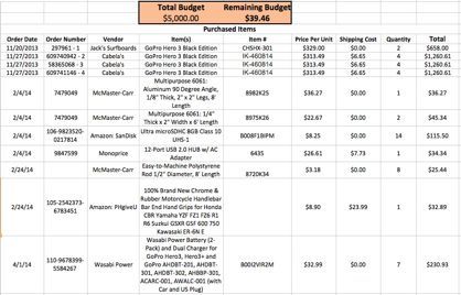
CREATING A TIME SLICING EFFECT – GOPRO ARRAY RIG & WORKFLOW                                                       RICHOS | 4

Imaging Science at RIT a total of 14 camera bundles and         curvature of the rig it must be understood that the angle of
8GB MicroSD Class 10 memory cards were purchased.               curvature cannot be too steep. This is to prevent the two
                                                                cameras on each end from seeing each other in their field
The rig design will take into consideration that the cameras    of view.
will be in their weatherproof casing. This will help
eliminate worry of damaging the cameras and give the
ability to shoot in a variety of conditions. The downside to
this casing is that is does not allow entrance to the USB
port on the side of the camera for power. We must solely
rely on battery power when shooting.

When planning the design of the rig we must consider the
dimensions of each individual GoPro. The dimensions of
the GoPro Hero 3 camera with the weatherproof housing
                                                                        Figure 2: Side-by-Side Dimensions for Line Array
and original stand are (8.5cm x 8cm x 5cm) [H x W x D].
This would take the total length of the rig to about 72cm       Understanding that each camera can be set to have a FOV
across without cameras spacing.                                 of 90 degrees, we can use this angle to determine our
                                                                overall arc angle of the rig without the two end cameras
The array will utilize 14 GoPro Hero 3 Black Editions in        seeing each other with the understanding that in a perfect
total. The horizontal curve will house 9 cameras across         line, the cameras will only see each other if they are facing
with the center camera (5th camera in from the end, titled      each other. Half the FOV angle can be used as our
“0M”) in the direct center of the rig. The choice was made      maximum angle of curvature because once that angle is
to make the point of camera center to be the point of the rig   reached the two end cameras will see each other. For this,
center instead of the lens center because the whole rig         40 degrees will be used instead of 45 degrees because this
would then be offset. This is because the GoPro cameras         allows for about 5 degrees of error within this maximum
have a lens center that is offset 6cm from the left, while      angle.
facing you, in it’s provided weatherproof casing. The
vertical section of the rig will house 5 additional cameras.    Knowing that we have a total of 9 cameras on the
The reasoning behind adding an additional camera to the         horizontal section of the rig, the problem can be split in
vertical section was decided on the basis that students were    half, using the middle camera as the starting point. This
interested in seeing how the vertical element on this rig       allows the other four cameras to pivot from this center
would look, so it was decided to enhance the effect on the      camera in determining the angle in which the camera
vertical section was made.                                      should sit. With a maximum angle of 40 degrees we can
                                                                divide this by the 4 pivot points created by the separated
                                                                cameras, wrapping around the arc. This would yield a 10-
                                                                degree difference created by each camera; however, we do
                                                                not want the angle to be this steep because we would be
                                                                close to reaching the 45-degree absolute maximum.
                                                                Dividing the previous 10-degree difference in half, a 5-
                                                                degree difference between each separated camera in
                                                                created, yielding a 20-degree arc.
         Figure 1: GoPro Hero 3 Front View Dimensions

This camera rig will be designed to have a set curvature so
the 72cm would also not take the length due to curvature or
camera spacing into consideration. The curve is essential
to the design to simulate a smoother rotation around the
subject. Instead of starting at one end of the rig and
essentially capturing a moment in time and tracking away
from the subject, the curvature allows for the subject to                          Figure 3: Arc Angle of Rig
remain the focus of the effect. When developing the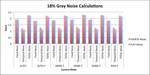
CREATING A TIME SLICING EFFECT – GOPRO ARRAY RIG & WORKFLOW                                                      RICHOS | 5

With the current angle of curvature predetermined to be 20     E. Demo Reel Overview
degrees from horizontal on both ends of the rig, this allows
for an addition of 8 cameras on each arm segment (addition     The demo reel will be made as if the product were being
of 24 total), a total of 38 cameras on the rig at one time     sold to RIT and its students. This will include both high
with the same radius of curvature and camera spacing. The      action shots from sports and other interesting scenes to
addition of these extra cameras would bring the rig’s          show off the basic capability of the system.
overall angle of curvature to a 40-degree angle, just barely
reaching the 45-degree threshold where the FOVs from the         The current shot list includes:
two cameras on the end would cross. The mathematics                  • High diving (rig half in and half out of water)
attempt to also take into consideration a 70-degree                  • Gymnastics team flips
overlapping camera FOV parallax, also known as the                   • Golf swings
convergence angle (α) in optics; however, when both the              • Cartwheel
12cm IOD separation and the 20-degree curvature were                 • Cornstarch bouncing on speakers
implemented physically, the size and feel of the rig became
more of how it was imagined.
                                                               F. Camera Characterization Overview
There are distinct differences between the current GoPro
array concepts and the design being implemented here.          In addition to these three main project goals, a camera
The addition of curvature to the typical line array model      characterization was preformed to obtain a better
will add a new feel to the look of these other high-speed      understanding of what the GoPro Hero 3: Black Edition
GoPro rigs. A vertical module, baring the same 20-degree       camera was doing under ideal shooting conditions. These
curvature will also be added to the center of the horizontal   tests included Noise, MTF, Dynamic Range/OECF, and
section. The final designed rig will resemble one of the       Color Reproduction.
grabbing claw games at retail stores, but the two bottom
arms will be flat to the surface normal, and the third arm     1) Noise
would be vertically perpendicular.
                                                               Noise is defined as the random variation of brightness or
                                                               color in an image caused by the imaging system itself or
A handgrip system is also implemented alongside a
                                                               the variation in the number of photons sensed at a given
standardized tripod mount for stable recording in all
                                                               exposure level. It is an effect of long shutter speeds, gain
environments. These two mounted pole grips will be
                                                               and well size. This is all done to correct exposure in low
attached to the bottom for handheld use, but its main
                                                               light situations.
purpose is to be mounted on a typical RIT Cage provided
tripod. Having the rig mounted during capture will result      Lack of noise is a key characteristic in an imaging system,
in fewer motion artifacts between each camera.                 but it is a constant battle between love noise levels and
                                                               high low light sensitivity. It is an important aspect when
D. Workflow Design Overview                                    choosing the ideal camera setup. A Macbeth chart shot with
                                                               different camera modes will be used in this analysis. There
The workflow created consists of a step-by-step of the         are two methods that we will use to analyze noise. One will
entire process. This includes a list of equipment needed, a    be between both the temporal and fixed noise
setup of the cameras on the rig, a process of effective        characteristics of the camera. The other method will be a
capture, a process of bringing the footage into post with      perceptual noise analysis based on standards set by Kodak
correct organization (a template will be created to            for film grain noise evaluation.
accommodate this specific workflow), a process on how to
align cameras in the editing software to achieve the desired   Kodak released a standard that they would use for
effect, and finally a process on optimized rendering and       determining noise. A 50-micron aperture would be used
output methods. The workflow will include all this             when analyzing film. Humans are not sensitive enough
information in a document to then be provided to students      spatially, to detect individual grains in the film, so the 50-
(hardcopy and an electronic copy on the provided               micron aperture was chosen after psychophysical
flashdrive) when checking out the rig at the RIT SoFA          experiments. These experiments show that the 50-micron
cage.                                                          aperture would be ideal to us as the metric for a grain on
                                                               the screen. This standard can be utilized today with digital
                                                               systems when compared to film. HD film is approximately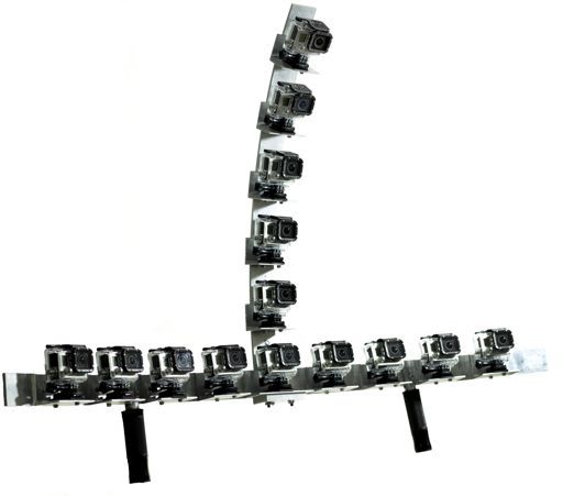
CREATING A TIME SLICING EFFECT – GOPRO ARRAY RIG & WORKFLOW                                                      RICHOS | 6

21mm in width. The resolution of the test cameras is:          turn cannot reproduce a uniform slanted edge. Analyzing
                                                               the steps will tell us the spatial resolution of the system.
                    1920 pixels in width.
                    So the pixels/mm is:                       3) Dynamic Range/OECF
                      1920        pixels
                           = 91.4
                       21          mm                          The dynamic range of a camera system refers to the range
        Convert that to microns and find the number            of exposures the system can register between the minimum
           of pixels in the 50 micron aperture:                exposure needed to produce a “usable” response and the
                      pixels          pixels                   maximum exposure the system can register, yet still
                91.4         = 0.0914                          collects “usable” data. This is commonly known as the
                       mm             micron
                           pixels                              range of stops of exposure a camera system can handle.
                  0.0914          ∗ 50microns
                           micron
                    = 4.57pixels ≈ 5pixels                     In 8-bit digital video cameras, the camera system converts
                                                               these exposures to digital code values between 0 and 255.
With this in mind, moving through each image in 5x5 pixel      If the exposures are too high for the system the code values
                                                               are forced to 255. If the exposures are too low for the
blocks, mimics the aperture size developed by Kodak and
                                                               system to detect, the code values are forced to 0. This is
takes the end standard deviation.                              referred to as clipping on the high end and crushing on the
                                                               low end. To test the dynamic range of the GoPro Hero 3:
Temporal and fixed noise will also be looked at for            Black Edition, we will shoot an ISO 14524 OECF chart
multiple images. Splitting these two aspects allows a          with each camera. Illuminance values of each patch on the
determination of where the noise is coming from. Fixed         chart will also be recorded for post-production analysis.
noise is the dark current of the system and remains constant
                                                               4) Color
through multiple images. Temporal noise on the other hand
is caused by read noise and interpolation.                     The color reproduction of a camera system is essentially a
                                                               subjective comparison between the two cameras of what
                             Nσ 2 Diff                         looks best. Some images that look the best to the average
               σ Temp =                                        consumer may not to a professional who must then
                              N −1
                                                               manipulate the image later in post-production. This
                                  Nσ 2 Diff                    professional in a video workflow desires a flatter profile for
               σ Fixed = σ 2 Ave −
                                     N −1                      easier and much more precise, color manipulation. This
                2         2        2
               σ Total = σ Temp + σ Fixed                      flatter profiler will help achieve the desired look of the
                                                               image.

2) Modulation Transfer Function (MTF)                          For a much more technical analysis, the Macbeth chart is
                                                               used to compared the actual reflectance values off the
The Modulation Transfer Function (MTF) is a description        patches. Chroma vs. Lightness arrow charts are used to
of the camera system’s spatial sensitivity. It shows how       determine color accuracy and analyze what the camera is
much detail the camera system can discern. To compare          doing. This will help explain if it is a fault of the camera or
MTF and aliasing characteristics of the camera system an       not. The Macbeth chart will be used under the same
ISO 12233 chart will be shot. There are many things that       lighting conditions as the grey card from our noise analysis.
influence the MTF including focus of the camera, the lens,
compression techniques, and the size of the sensor. For        The modes being tested for comparison on the GoPro Hero
this analysis the focus will be on the center and the left     3: Black Edition include, AUTO, AUTO-T, 3000K-T,
slanted edge and the frequency bars on the bottom.             5500K-T, 6500K-T, and RAW-T.
Comparing the center and left slant edges will show us how
the Fisheye lens will degrade detail. Analysis in post-
production is then done to compare the results. The                            III. METHODS/PROCEDURES
Modulation Transfer Function is defined as:

                            ModulationIn                       A. The Build
                   MTF=
                            ModulationOut
                                                               In the machine shop located at RIT there were many
Modulation is defined as the difference between two            different mechanical engineering practices involved to
extremes on the edge. In this situation it is the difference   reach the end result. Initially, we had to bend a bar of 1/4"
between black and white on the ISO 12233 chart. The            x 2" x 6' Multipurpose 6061 Aluminum in a metal roller to
reason for the use of a slanted edge is because it acts as a   reach the twenty degree mark we were looking for. This
slight stair step. Pixels in these cameras are square and in   took about six hours of work and fine adjustment, to get as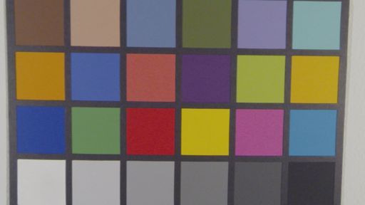
CREATING A TIME SLICING EFFECT – GOPRO ARRAY RIG & WORKFLOW                                                      RICHOS | 7

close as we could to the designed specification. After he      handgrips, located in the Rig and Handgrip case, can also
initial horizontal arc was finalized we started machining 14   be attached and detached using the same provided machine
total L-shaped brackets (Multipurpose 6061: Aluminum 90        screws, wrench, and Hex wrench.
Degree Angle, 1/8" thick, 2" x 2" legs, 8' length) to hold
each individual camera. These all had to be made identical,    Cameras are labeled both on the weatherproof casing and
so that the angles were practically the same between each      the camera itself. For organizational purposes they should
bracket, allowing for minimal differentiation between each     be placed on the rig from the perspective of the user; “L”
of the cameras. The next challenge was to make sure that       for left, “R” for right, “V” for vertical, and “M” for middle.
the vertical arm element was perfectly orthogonal to the       The cameras on the horizontal arc should resemble the
base arc. This was crucial so that the vertical element        order: 4L, 3L, 2L, 1L, 0M, 1R, 2R, 3R, 4R from left to
would be directly in line with the base camera. After this     right. The cameras on the vertical element should resemble
was successfully accomplished, a tripod mount was built        the order: 5V, 4V, 3V, 2V, 1V, and 0M from top to bottom.
and fit (to the SoFA tripod mounts) so that it would match     The cameras should be attached to the GoPro base mounts,
the angles of the horizontal arc and allow for solid           already secured to the individual brackets and rested on the
connection between the rig and the tripod.                     plastic stopper.

After all this was made and assembled, we added spacers        WiFi recording has been setup to work with these specific
(made from an Easy-to-Machine Polystyrene                      cameras. The GoPro WiFi remote is located in the
1/2" Diameter, 8' Length Rod) behind each of the L-            provided cage toolbox. Once the cameras have been
brackets. These spacers were accurately cut out to be the      mounted the camera’s WiFi signal must be turned on by
exact length (0.657”) so that when each camera is tilted to    selecting pressing the button on the left side of the camera
rest on them, it would allow for a perfect ninety-degree       (facing you). A blue light will begin flashing, indicating
angle perpendicular to the horizontal rig, for the mounted     that the camera’s WiFi is active. Do this for the 13
camera. Through the time of construction, there was an         remaining cameras and then press the power button on the
issue regarding whether or not the 3M-tape, located on the     GoPro WiFi remote. The cameras will begin to turn on,
bottom of the camera mounts, would be strong and resilient     one at a time. Once the remote indicates on its LCD screen
enough over an extended period of time. It was decided to      that 14 cameras are connected, the cameras are all
hard mount the camera mounts to each of the arc elements       controllable. After using this remote now several times, I
with threaded screws to ensure the cameras and mounts          suggest taking a 5 second test shot before actually using it
would not be either moving or falling off over the rig's       to shoot your scene. This allows all of the cameras to sync
lifetime.                                                      within 1 – 2 frames of each other after the first remote use.
                                                               Cameras can also be powered down simultaneously using
Almost every machine in the shop was used in order to          the GoPro WiFi Remote as well.
complete this rig. These include lathes, Bridgeport mills,
grinders, metal benders, the drill press, automatic cut-off    Active GoPro batteries with the WiFi in use last
saws, files, and many other smaller tools. These were all      approximately 1 hour. To compensate for this poor battery
needed to make sure that the rig would be as geometrically     life, the decision was made to purchase another set (14)
perfect as it needed to be to allow for the most accurate      GoPro batteries and duel battery charging systems (7) that
shots.                                                         will also be provided at cage checkout. These will be
                                                               located in the Batteries, Cables, and Chargers case.
B. Assembly and RIT SoFA Cage Checkout
                                                               C. Camera Characterization Procedure
Rig assembly was designed to be as easy as possible for
students in SoFA. The rig comes packaged with 3 main           1) Noise
cases:
    • Rig and Handgrip case                                    For this test a MacBeth Chart and Kodak 18% Gray Card
    • Camera and Toolbox case                                  are captured. The baseline will be the camera’s AUTO
    • Batteries, Cables, and Chargers case                     mode, lit to an f/2.8. To further test the systems we will
                                                               compare changes in noise from the color modes from
The screws connecting the vertical element to the              AUTO normal and all of the Protune modes.
horizontal arc are 3, 1/4” – 20 threaded machine screws
with standard nuts attached. This base also holds the          Below is a diagram for the lighting setup for the Macbeth
middle camera (CAM 0M) and plastic stopper. Both the           chart. Two 300W light should be on opposite sides and a
screws and plastic stopper must be unscrewed before            light meter should be used to ensure that there is an even
attaching the vertical element. Once the vertical element is   f/2.8 lighting. The lights should be adjusted spot or flood
in place, all four pieced must be placed on again (1/4” – 20   until the meter reads evenly. The camera, lights and
x3 and plastic stopper x1). To fasten the 1/4” – 20 machine    Macbeth chart should be positioned the same height off the
screws securely, a wrench and corresponding Hex wrench         ground. Adjust the charts on a wall so that the chart fills up
is included in the provided toolbox at checkout. The rig’s     the field of view of the camera.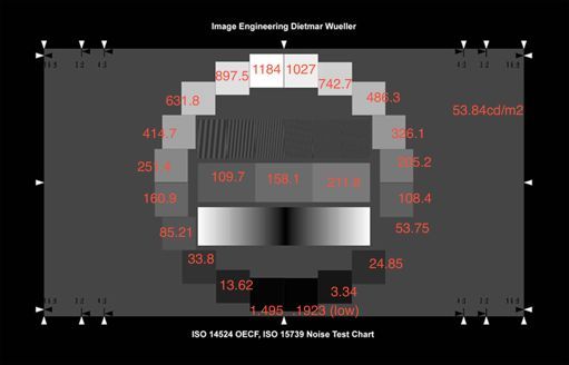
CREATING A TIME SLICING EFFECT – GOPRO ARRAY RIG & WORKFLOW                                                       RICHOS | 8

                                                                1) ISO12233 Chart

                                                                     a) GPH3 [ISO 640; WB AUTO; 1/60th; f/2.8; 1080p
                                                                               59.94fps]

                                                                     b) GPH3 [ISO 640; WB AUTO-Protune; 1/60th; f/2.8;
                                                                               1080p 59.94fps]

                                                                     c) GPH3 [ISO 640; WB 3000K-Protune; 1/60th; f/2.8;
                                                                             1080p 59.94fps]

              Figure 4: Lighting diagram for charts
                                                                     d) GPH3 [ISO 640; WB 5500K-Protune; 1/60th; f/2.8;
                                                                             1080p 59.94fps]
The scene will be shot 6 times with varying camera modes.
Below are the shots and their settings/descriptions:                 e) GPH3 [ISO 640; WB 6500K-Protune; 1/60th; f/2.8;
1) Macbeth Chart and Kodak 18% Gray Card                                     1080p 59.94fps]

     a) GPH3 [ISO 640; WB AUTO; 1/60th; f/2.8; 1080p
                                                                     f) GPH3 [ISO 640; WB RAW-Protune; 1/60th; f/2.8;
              59.94fps]                                                        1080p 59.94fps]

     b) GPH3 [ISO 640; WB AUTO-Protune; 1/60th; f/2.8;
                                                                3) Dynamic Range/OECF
              1080p 59.94fps]
                                                                The ISO 14524 OECF Chart should be warmed up for 30
     c) GPH3 [ISO 640; WB 3000K-Protune; 1/60th; f/2.8;         minutes before shooting and placed in a completely dark
             1080p 59.94fps]                                    room (in Studio B) with no light spill. The camera should
                                                                be at the same height as the OECF chart patches. Measure
     d) GPH3 [ISO 640; WB 5500K-Protune; 1/60th; f/2.8;         and record the luminance values for each OECF patch with
             1080p 59.94fps]                                    a colorimeter. Take a 5 second shot with each camera
                                                                mode listed below.
     e) GPH3 [ISO 640; WB 6500K-Protune; 1/60th; f/2.8;
                                                                1) ISO14524 OECF Chart
             1080p 59.94fps]
                                                                     a) GPH3 [ISO 640; WB AUTO; 1/60th; f/2.8; 1080p
     f) GPH3 [ISO 640; WB RAW-Protune; 1/60th; f/2.8;                          59.94fps]
              1080p 59.94fps]
                                                                     b) GPH3 [ISO 640; WB AUTO-Protune; 1/60th; f/2.8;
2) Modulation Transfer Function (MTF)                                          1080p 59.94fps]

The ISO12233 chart should be mounted on a wall. The
                                                                     c) GPH3 [ISO 640; WB 3000K-Protune; 1/60th; f/2.8;
camera should be brought up to the same height and
                                                                             1080p 59.94fps]
leveled so that the edge of the frame lines up with the
points of the arrows. In order to get an accurate reading the
camera needs to be lined up as accurately as possible. Set           d) GPH3 [ISO 640; WB RAW-Protune; 1/60th; f/2.8;
up two 300W lights on opposite sides. The lighting                             1080p 59.94fps]
diagram used in Figure 4 can also be used for this test.
                                                                4) Color
The lights, camera and chart should all be at the same
height. Use a light meter to ensure even lighting. The light    For this test, just like in the Noise test, a MacBeth Chart is
meter should read 2.8 everywhere. Once you have the             captured. The baseline will be the camera’s AUTO mode,
lights set up correctly, you need to check the base settings    lit to an f/2.8. To further test the systems we will compare
on the camera. Take about a 5 second shot with each             changes in noise from the color modes from AUTO normal
camera mode:                                                    and all of the Protune modes.

                                                                Below is a diagram for lighting setup for the Macbeth
                                                                chart. Two 300W light should be on opposite sides and a
                                                                light meter should be used to ensure that there is an even
                                                                f/2.8 lighting. The lights should be adjusted spot or flood
                                                                until the meter reads evenly. The camera, lights and
CREATING A TIME SLICING EFFECT – GOPRO ARRAY RIG & WORKFLOW                                                 RICHOS | 9

Macbeth chart should be positioned the same height off the
ground. Adjust the Macbeth chart on a wall so that the
chart fills up the field of view of the camera. The lighting
diagram used in Figure 4 can also be used for this test.

1) Macbeth Chart

     a) GPH3 [ISO 640; WB AUTO; 1/60th; f/2.8; 1080p
              59.94fps]

     b) GPH3 [ISO 640; WB AUTO-Protune; 1/60th; f/2.8;
              1080p 59.94fps]

     c) GPH3 [ISO 640; WB 3000K-Protune; 1/60th; f/2.8;          Figure 6: Finder; FOLDER_TEMPLATE” Overview
             1080p 59.94fps]
                                                               4) Open GoPro Studio software.
     d) GPH3 [ISO 640; WB 5500K-Protune; 1/60th; f/2.8;        5) Import new files with the “IMPORT NEW FILES”
             1080p 59.94fps]                                       button
                                                               6) Select “Original Footage” with all clips in sub
     e) GPH3 [ISO 640; WB 6500K-Protune; 1/60th; f/2.8;            folders.
             1080p 59.94fps]                                   7) On mid-bottom, select “Save to:”
                                                               8) Select “Transcode_mov_FLAT” to save all clips to.
     f) GPH3 [ISO 640; WB RAW-Protune; 1/60th; f/2.8;
                                                               9) Select all imported clips on the right with [cmd +
              1080p 59.94fps]                                      A] on Mac.
                                                               10) Once all clips are selected, make sure the image
                                                                   size is;
                                                                        a. Source (1920x1080)
                 IV. WORKFLOW DESIGN                                    b. Frame rate source (59.94p)
                                                                        c. Quality: High
A. Data Management/GoPro Studio Workflow                                d. Select – Remove fisheye
                                                                        e. Select – Remember settings for future
                                                                              clips
                                                                        f. Click OK
                                                                        g. With all clips still selected, Select - Add
                                                                              clips to conversion list
                                                                        h. Once on the right side panel select all
                                                                              clips again and select “Convert”
                                                               11) Once converted select “Proceed to Step 2.”
                                                               12) One by one, select each clip, click “1970s”
                                                               13) In the presets tab in the bottom right corner, select
                                                                   “none.”
                                                                   NOTE: You must select each clip individually,
                                                                   select “1970s” then “none” on presets. (This does
                Figure 5: GoPro Studio Overview
                                                                   not work for select all) If you do not pre-form this
                                                                   step, your output clips will have a significant
    1) GoPro studio must be installed first. This program          increase in saturation and overall color shift.
        not only allows for easy fisheye removal, but also     14) Your exported clips are now located in the
        installs the Cineform (Figure 5).                          “Transcode_mov_FLAT” folder, outside of the
    2) “NO_NAME” GoPro Memory Card.                                individual camera folders.
             a. Copy over ONLY MP4 files to                             a. Each clip will now have the camera ID
                  “FOLDER_TEMP”                                               prefix appended to the original clip
             b. 1080p .MP4 Original → Flashdrive →                            name.
                  ”FOLDER_TEMPLATE” → “Original                15) ex. GoPro1234 → 0M_GoPro1234
                  Footage” → “0M…”                                      a. Clips can now be dragged into their
        NOTE: Do not rename original clips.                                   specific camera folders for organization
    3) Place each camera .MP4 in specific clip folder in                      without being changed by the GoPro
        “Original Footage” (Figure 6).                                        Studio software.
CREATING A TIME SLICING EFFECT – GOPRO ARRAY RIG & WORKFLOW RICHOS | 10
NOTE: The average conversion rate ratio when a. Arrow over one frame and set another
converting the original GoPro .MP4 clips to the key frame.
Flat .mov format is 10:1. In this case that means 9) Place a key frame before the action where you wish
to begin slow-motion on the starting camera (but
for every 1 gigabyte of information you are
still on the same selected clip).
converting, that will be equal to about 10 10) Place a key frame on the same clip after the effect
gigabytes of information when Flattening the where you wish the speed to return back to
image through the GoPro Cineform conversion in normal.
the GoPro Studio software. 11) Between the 1 and 2keys, drag the level to ~33%
(30%-50%).
NOTE EXAMPLE: One of my test shots early on, 12) Between keys 2 and 3, drag the level down all the
way to 1%. This will effectively stop all the
I took about 90 seconds of video at 1080p, 60fps,
action between those two key frames (technically
Narrow FOV, AUTO WB. For all 14 cameras it slowed to 1%, but visual looks paused)
totaled to be about 1.1GB in the .MP4 format 13) Between keys 3 and 4, drag the level down
encoded on the Class 10 8GB MicroSD card. between 50% and 75% to create a smooth ramp-
When converting and flattening the image I up.
reached roughly 120GB. 14) Leave the last key frames untouched so the action
goes back to the normal speed. (Shown in Figure
8)
B. Adobe Premiere Pro Workflow
1) Open “GoPro_ARRAY_RIG_TEMPLATE”.
Located on the “GOPRO_RIT” flashdrive in the
Adobe Premiere folder. (Figure 7)
Figure 8: Adobe Premiere Pro CC – Time Remap Overview
C. Adobe After Effects Workflow
1) With your last Adobe Premiere Pro project file
open up Adobe After Effects.
2) Select the single shot you want to continue adding
Figure 7: Finder; “GOPRO_RIT” flashdrive Overview the bullet time effect to and copy all of the camera
layers within that shot with [cmd + c].
3) In Adobe After Effects open up a new composition
2) Save as… as your own project name.
[cmd + n]
3) Import camera media into specified folder under
a. Make sure you have your composition
“Transcode_mov_FLAT”.
frame rate set to the native 59.94fps Drop
4) Drag all clips onto timeline from each camera
Frame of the GoPro media being used.
folder onto their designated video track. (Onto the
4) Paste the Adobe Premiere Pro content [cmd + v]
already created video sequence)
into the layers timeline at bottom section of After
5) Cut each clip to length of cam 0M and sync all 14
Effects. This step should copy all of the media
cameras vertically via slate.
from the selection in Premiere Pro and any applied
a. Place marker on each clip at slate – to be
markers and key frames.
used for later.
a. Line up all of the markers, key frames,
6) Select camera at first desired position.
and content just like how they were in
7) Under effect controls, select/enable “Time Re-
Premiere Pro.
mapping”.
b. Ordering the cameras should be done at
8) Place key frame at the frame you wish to begin the
this step by dragging the layers at the
effect.
bottom to the position desired. The top
camera should be the camera you wishCREATING A TIME SLICING EFFECT – GOPRO ARRAY RIG & WORKFLOW RICHOS | 11
the see first. For example, if you wanted allow for less image scaling. As a base, I
to start at CAM 4L and interpolate normally shot about double the distance I
around the horizontal arc, order your clip normally would have with a single
in the order 4L, 3L, 2L, 1L, 0M, 1R, 2R, camera.
3R, 4R from top to bottom. b. NOTE: If you adjust the rotation or scale
5) Scrub to the location of the first frame where the of either the first of the last camera, you
first 1% Time Remapping key frame is located. must adjust both the scale and rotation of
6) Select all of the clips [cmd + a] and duplicate these the first and last camera in your main
clips within the timeline [cmd + d] composition to match each other.
7) Without clicking anywhere else and these 18) Back in the main composition, to clean things up,
duplicated layers selected, cut the media on these you can delete the all the camera layers from the
layers down to a single frame by holding the timeline except for the Pre-Composition, the first
Option key and hitting the left bracket then right camera, and the last camera.
bracket keys. {Option + [} then {Option + ]} 19) Trim the first camera layer to end when the Pre-
8) With these duplicated clips (and them all selected) a Composition layer starts and trim the last camera
new composition has to be made with the layer to start when the Pre-Composition layer
duplicate clips within it. To do this, a Pre- ends.
Composition can be created by going to Layer → 20) Select all of the clips and enable Time-Remapping
Pre-Compose [Shift + cmd + c] and clicking OK. [Option + cmd + t]. You should now be able to
a. These duplicated clips are now within the see the key frames you made in the Premiere Pro
single composition (default name, Pre- project.
Comp 1) 21) Select the Pre-Composition layer and enable Pixel
9) Go into the Pre-Composition setting [cmd + k] and Motion Frame Blending.
change the duration of the composition to match a. Right click the Pre-Composition layer
the number of cameras you will be interpolating b. Frame Blending dropdown menu
around, plus an additional frame. c. Select Pixel Motion
a. Horizontal curve; 0;00;00;10 22) NOTE THIS MINI LIST CAN ONLY BE DONE
b. Vertical curve; 0;00;00;06 IF YOU HAVE THE TWIXTOR AE PLUG-IN
10) Offset each of the individual frames by one to the a. Apply Twixtor to the Pre-Composition
right. layer and tweet these attributes
11) Select all the clips and hit the T key to open up b. Color Source: Reference your Pre-
Opacity adjustments. Composition layer
12) Starting with the first frame, extend it out one c. Input Frame Rate: 59.940
more frame and adjust the opacity to about 40%. d. Motion Vectors: Best
13) Place you scrub position at the point between both e. Image Prep: Contrast/Edge Enhance
frames so that you can see both images f. Speed Perfect: 50%-75%
overlapping on the monitor. g. Frame Interp: Motion Weighted Blend
14) Adjust the second image by clicking and dragging, h. Smart Blend: Selected
to overlap the main subject you are pulling the 23) Select the last key frame associated with the Pre-
effect on (or any stable markers in the scene) so Composition layer Time-Remapping and drag it to
that they line up correctly. the duration you wish the effect to be.
a. Continue doing this for the rest of the 24) Select the key frames from the last camera from
camera layers until they are all aligned. the end of the Pre-Composition layer on. Drag
15) With the opacity back to 100% for all of the clips, them over to start when the Pre-Composition layer
selected all of the clips again and hit the R key to ends so the last camera layer can pic back up.
adjust the rotating of each frame. Choose a Your ending composition should look similar to
position in the frame where you believe that it is Figure 9 below.
as horizontal to the scene as possible and use that
as your reference.
16) To compensate for some of your clips being out of
the monitor frame from both the position and
rotation adjustments, scaling must be applied.
Select all of the clips again and hit the S key to
bring up scaling options.
17) Scale each clip up to the same amount, but just
enough so that all of the frames are in the monitor
frame.
a. NOTE: When shooting, stand further
back that you would normally shoot to
Figure 9: Adobe Premiere Pro CC – Time Remap OverviewCREATING A TIME SLICING EFFECT – GOPRO ARRAY RIG & WORKFLOW RICHOS | 12
V. RESULTS & DISCUSSION
A. System Design
The manufacturing process was crucial in the success of
the envisioned project. Using the various tools throughout
this process provided the opportunity to expand my
learning experiences here at RIT. In addition, the closeness
with the hands-on experience was fundamental in
guaranteeing that this project would fulfill its expectations.
The entire system was designed around the ease of use for
the producer and the end user, in that it can easily be
broken down and packed away efficiently. Without this
ease of assembly taken into account, the rig would not be a
desirable tool for the RIT SoFA community. This project
was able to develop a working, easy to use prototype, but
also one that has the future user in mind (Figures 10, 11, Figure 12: GoPro Rig Straight Vertical Element – No Cameras
12, 13).
Figure 10: GoPro Rig Curved Vertical Element – No Cameras
Figure 13: GoPro Rig Straight Vertical Element – Cameras
B. Camera Characterization Analysis
1) Noise
The noise calculations we’re calculated for all the camera
modes, including the Protune modes. It was a surprise to
me that the Flat image overall had less noise in both fixed
Figure 11: GoPro Rig Curved Vertical Element – Cameras and temporal methods, with the exception of AUTO,
5500K-T, and RAW-T mode (Figure 14) with slightly
higher fixed noise in the Flat image. My original
expectations of these results were the exact opposite due to
the encoding of the flat image from the original fisheye
image.CREATING A TIME SLICING EFFECT – GOPRO ARRAY RIG & WORKFLOW RICHOS | 13
Figure 17: Noise RGB MacBeth chart Black Patch – Fisheye
Figure 14: Gray Card Noise – Fisheye vs. Flat vs. Flat
The purpose of the 5x5 blocks, previously described, is to
mimic the visual response of the observer averaging pixels. 2) Modulation Transfer Function (MTF)
The standard deviation is calculated from the averages of
these 5x5 blocks. This calculation was done over the red,
green, and blue channels of the white, ~18% gray, and The graphs in Figures 18, 19, 20, and 21 below show the
black patches located on the MacBeth chart. The results MTF curves of camera system based on the test shots from
are very similar to those of the 18% Gray Noise the ISO12233 test chart.
Calculation results shown in Figure 12, but a clearer
understand of how each color channel is reacting is shown.
The AUTO and AUTO-T modes are the most interesting to
observe. Under the gray patch, the blue channel exceeds
both the green and red channel by almost double, but only
under the AUTO-T mode in the black patch does this same
result occur. With the 5500K-T and the 6500K-T modes it
makes sense again that the blue channel is much higher
because it was compensating for the forced set white
balance from the scene.
Figure 18: GPH3 MTF – Center Vertical ISO12233; AUTO;
1080p 60fps
Figure 15: Noise RGB MacBeth chart White Patch – Fisheye
vs. Flat
Figure 19: GPH3 MTF – Center Horizontal ISO12233; AUTO;
1080p 60fps
Figure 16: Noise RGB MacBeth chart Gray Patch – Fisheye vs.
FlatCREATING A TIME SLICING EFFECT – GOPRO ARRAY RIG & WORKFLOW RICHOS | 14
utilizing the luminance values measured from the chart.
We transformed the luminance values of the OECF patches
into specific values of exposure that corresponded with the
average pixel signal value of each patch captured by the
camera systems. These exposure values were graphed with
their respective signal values.
Figure 20: GPH3 MTF – Left Vertical ISO12233; AUTO; 1080p
60fps
Figure 23: GPH3 ISO 14524 OECF Annotated Chart
Figure 21: GPH3 MTF – Left Horizontal ISO12233; AUTO;
1080p 60fps
The MTF of the camera system introduces the problem of a
potential difference between both the vertical to horizontal
and center to edge readings. In both of the horizontal slant
edge readings, a boost in contrast is applied near the middle
region of frequencies; however this boost differs slightly
between the center and left edge readings. The blue
channel is boosted much higher than green or red, and also
much higher near the top middle edge of the chart. This
Figure 24: GPH3 ISO 14524 OECF; AUTO; 1080p 60fps
could be a result of GoPro’s fisheye lens implementation
and its physical lens falloff.
Figure 22: GPH3 MTF – Frequency Bars ISO12233; AUTO;
1080p 60fps
Aliasing artifacts are also very apparent, even when
examining the lower regions of the frequency bars,
referring to Figure 22. Again, this could be due to the
signature fisheye lens of the GoPro camera systems, but
should still be accounted for. Figure 25: GPH3 ISO 14524 OECF; AUTO-T; 1080p 60fps
3) OECF
The graphs in Figures 24, 25, 26, and 27 show the OECF
curves of camera system based on the test shots of the ISO
14524 OECF chart, all shot at normal exposure as well asCREATING A TIME SLICING EFFECT – GOPRO ARRAY RIG & WORKFLOW RICHOS | 15
appearance of a “flat” color profile. In normal RAW data
implementation the data represented in the OECF curve
should be linear, instead the profile representing “RAW”
data in the GPH3 camera systems looks to flatten out their
image to mimic the “RAW look”. Colorists and any other
post-production editors should take note when grading their
footage shot on this camera.
4) Color Reproduction
Color Reproduction in the GoPro camera system can be
measured both subjectively and objectively. The camera
has several built in color modes when switching to Protune
mode, but in this analysis the AUTO, AUTO-T (Protune),
Figure 26: GPH3 ISO 14524 OECF; 3000K-T; 1080p 60fps
3000K-T (Protune), 5500K-T (Protune), 6500K-T
(Protune), and RAW-T (Protune) were used.
Just by looking at the figures below using a MacBeth chart,
you can clearly see the differences when switching between
the modes under the same lighting conditions. When
comparing the differences between the AUTO and AUTO-
T modes a large shift in lightness occurs. We see that a
flatter look is achieved, but no hue shift is apparent when
looking at the a* b* plot, just a shift in L* and a slight shift
in C* making the patches appear less chromatic.
Figure 27: GPH3 ISO 14524 OECF; RAW-T; 1080p 60fps
Examining these figures closer, we can see that for the
most part the camera systems are relatively alike in how
they transcribe exposure values to signal code values
except in RAW-Protune mode. AUTO mode looks as if its
response is what we expected it to be by providing a decent
contrast between low, mid, and high signal code values;
however, within the AUTO mode OECF, the red and green Figure 28: DeltaE00 Between Camera Modes
channel looks as if they die off and clip much sooner than
the blue channel. When coming from the AUTO-Protune
mode to the straight AUTO mode, it is clearly visible that it
attempts to replicate a flatter profile as the lower signal
code values on the left have steep slope. As exposure
increases the code value slope starts to become flatter.
This slope allows for finer color adjustments in post-
production.
The 3000K-Protune mode preforms this same theory, but
allows for a shift in white balance for a 3000K Blackbody.
Knowing the illuminant source of the ISO 14524 OECF
chart to be Tungsten based, the result of having an increase
in the blue channel and a decrease in the red channel to Figure 29: GPH3 AUTO color mode
balance for this warmer source makes sense.
GoPro RAW-Protune, in relation to the other three camera
modes, is not comparable. The purpose of this mode
according to GoPro is to create a “flat” color profile for
more accuracy and freedom when color-grading in post-
production; however, what we are seeing here is theCREATING A TIME SLICING EFFECT – GOPRO ARRAY RIG & WORKFLOW RICHOS | 16
Figure 30: GPH3 AUTO-T color mode Figure 34: GPH3 5500K-T color mode
Figure 31: L* versus C* graph – Reference AUTO vs. AUTO-T
Figure 35: L* versus C* graph – Reference AUTO vs. 5500K-T
Figure 32: GPH3 3000K-T color mode
Figure 36: GPH3 6500K-T color mode
Figure 33: L* versus C* graph – Reference AUTO vs. 3000K-T
Figure 37: L* versus C* graph – Reference AUTO vs. 6500K-TCREATING A TIME SLICING EFFECT – GOPRO ARRAY RIG & WORKFLOW RICHOS | 17
things that could have been different that would strengthen
the rig. For instance, most of the parts would have a
smaller tolerance if they were made with an automated
machine, instead of by hand. This would have cut down on
slight differences between parts and could make the rig
even more accurate.
With the time, resources, and personal at my disposal, this
project turned out just as it was envisioned. This rig
successfully shows that a mobile time-slicing rig with a
working vertical element is feasible and can be
implemented as a creative tool for the students within the
Figure 38: GPH3 RAW-T color mode School of Film and Animation at Rochester Institute of
Technology.
VII. RESOURCES
[1] Gopro hd hero 3 black edition technical specs. (2013,
October). Retrieved from
http://gopro.com/cameras/hd-hero3-black-edition
[2] Ashley, T. (2013, March 02). Gopro 3 black: Hero or
zero?. Retrieved from
http://tashley1.zenfolio.com/blog/2013/3/gopro-3-
black-hero-or-zero
Figure 39: L* versus C* graph – Reference AUTO vs. RAWT [3] Clade, D. (2013, November 12). A fascinating look at
how gopro became the best-selling camera in the
A similar shift occurs with the 3000K-T mode when world. Retrieved from
compared to AUTO mode; however, this shift is greater http://petapixel.com/2013/11/12/fascinating-look-
than that of the AUTO-T mode. Both the 5500K-T and gopro-became-popular-camera-world/
6500K-T modes show similar results when compared to the [4] Pelz, J. (2013). Vision and psychophysics: Class notes
other modes. A larger hue shift occurs because of the on convergence. Unpublished raw data, College of
forced white balance compensation. RAW-T mode is Imaging Science, Rochester Institute of Technology,
compared to AUTO mode to understand the appearance of Rochester, NY.
a “flat” profile. When viewing the image patches an
obvious hue shift is occurring because the of tungsten
based light source illuminating the MacBeth chart.
Observing the Lab plot with AUTO as the reference, a
larger shift in all the patches occurs in both regions. Colors
are getting much more desaturated and less chromatic
giving the appearance of a “flat” color profile, but going
back quickly to our RAW-T OECF results we find this
“flat” profile to not be the linear data we see in normal
RAW data implemented in high end camera systems.
Although the AUTO mode does provide an acceptable
image in terms of color, any of the Protune options should
be utilized if there are plans to color-grade the footage in
post-production. These modes allow for more creativity to
the colorist because it gives them more information to work
with in a post-production workflow.
VI. CONCLUSION
Moving forward with this project, there is still a lot of work
that can be done to make it better and allow for different
variations. The prospect for the addition of arc extensions
in the future is a real possibility due to the open-ended
arms used in construction. While this project did turn out
very well and works just as it was designed, there areCREATING A TIME SLICING EFFECT – GOPRO ARRAY RIG & WORKFLOW RICHOS | 18
VIII. APPENDIX B. MacBeth Color Checker – RGB Patch Data
AUTO (Fisheye) - White
A. Noise – Gray Card Data
R G B
AUTO (Fisheye) 187.6354984 186.0494277 186.2503838
Fixed Noise Temporal Noise TOTAL Noise AUTO (Fisheye) - Gray
1.9098 1.2029 2.2571 R G B
AUTO (FLAT) 88.05776062 87.02837595 90.9818429
Fixed Noise Temporal Noise TOTAL Noise AUTO (Fisheye) - Black
1.9241 1.1042 2.2184 R G B
33.5776501 31.79737731 38.55567738
AUTO-T (Fisheye)
AUTO-T (Fisheye) - White
Fixed Noise Temporal Noise TOTAL Noise
R G B
1.8049 1.2647 2.2039
194.3188457 191.9416254 191.857287
AUTO-T (FLAT)
AUTO-T (Fisheye) - Gray
Fixed Noise Temporal Noise TOTAL Noise
1.7989 1.1407 2.1301 R G B
116.3105127 113.7883426 116.1176703
AUTO-T (Fisheye) - Black
3000K-T (Fisheye) R G B
Fixed Noise Temporal Noise TOTAL Noise 57.77597474 54.71325819 62.54576554
1.8298 1.2632 2.2235
3000K-T (FLAT) 3000K-T (Fisheye) - White
Fixed Noise Temporal Noise TOTAL Noise R G B
1.8635 1.1541 2.1919 201.0578483 198.879172 199.2965221
3000K-T (Fisheye) - Gray
5500K-T (Fisheye)
R G B
Fixed Noise Temporal Noise TOTAL Noise
122.6058068 120.4003772 123.1995965
1.8847 1.3126 2.2967
3000K-T (Fisheye) - Black
5500K-T (FLAT)
R G B
Fixed Noise Temporal Noise TOTAL Noise
62.02605149 59.42515679 67.61370115
1.9085 1.2062 2.2577
6500K-T (Fisheye) 5500K-T (Fisheye) - White
Fixed Noise Temporal Noise TOTAL Noise
R G B
1.8852 1.2414 2.2572
229.2025788 195.5498004 153.3497654
6500K-T (FLAT)
5500K-T (Fisheye) - Gray
Fixed Noise Temporal Noise TOTAL Noise
R G B
1.9187 1.1523 2.2381
141.0712249 115.1171001 79.58817596
RAW-T (Fisheye) 5500K-T (Fisheye) - Black
Fixed Noise Temporal Noise TOTAL Noise R G B
1.8152 1.2647 2.2123
RAW-T (FLAT)
72.20968379 57.61286786 43.82991974
Fixed Noise Temporal Noise TOTAL Noise
1.8322 1.139 2.1574You can also read