Kerf-Canceling Mechanisms: Making Laser-Cut Mechanisms Operate Across Different Laser Cutters
←
→
Page content transcription
If your browser does not render page correctly, please read the page content below
Kerf-Canceling Mechanisms: Making Laser-Cut
          Mechanisms Operate Across Different Laser Cutters
      Thijs Roumen, Ingo Apel, Jotaro Shigeyama, Abdullah Muhammad, and Patrick Baudisch
                                       Hasso Plattner Institute
                                         Potsdam, Germany
                                       first.lastname@hpi.de

ABSTRACT
Getting laser-cut mechanisms, such as those in microscopes,
robots, vehicles, etc., to work, requires all their components
to be dimensioned precisely. This precision, however, tends
to be lost when fabricating on a different laser cutter, as it is
likely to remove more or less material (aka “kerf”). We ad-
dress this with what we call kerf-canceling mechanisms.
Kerf-canceling mechanisms replace laser-cut bearings, slid-
ers, gear pairs, etc. Unlike their traditional counterparts,
however, they keep working when manufactured on a differ-
ent laser cutter and/or with different kerf. Kerf-canceling
mechanisms achieve this by adding an additional wedge ele-
ment per mechanism. We have created a software tool Kerf-
Canceler that locates traditional mechanisms in cutting plans
and replaces them with their kerf-canceling counter-
parts. We evaluated our tool by converting 17 models found
online to kerf-invariant models; we evaluated kerf-canceling
bearings by testing with kerf values ranging from
0mm and 0.5mm and find that they perform reliably inde-
pendent of this kerf.
Author Keywords
Personal Fabrication, Portable Fabrication, Sharing, Reuse.
CSS Concepts
• Human-centered computing~Human computer inter-                                              Figure 1: This laser-cut microscope (based on thingiverse id:
                                                                                              31632) contains three types of mechanisms that allow the mi-
action (HCI); Interactive Systems and Tools.
                                                                                              croscope to adjust focus. By using kerf-canceling mechanisms,
• Applied Computing~Operations Research; Computer                                             the focus adjustment operates reliably, independent of how
Aided Manufacturing.                                                                          much material the laser cutter that produced the microscope
INTRODUCTION                                                                                  removes (kerf).
While laser cutting allows fabricating a wide range of objects                                The main challenge in creating functional mechanisms is that
[4], arguably the most interesting set of models are those that                               all parts have to be dimensioned precisely [18], model
perform a mechanical function, such as robotic arms (e.g.                                     creators achieve this by means of careful tuning.
GrabCAD “braccino”), vehicles (e.g. ugearsmodels.com)                                         Unfortunately, this tuning tends to get lost, when the model
and optical equipment (e.g. thingiverse id 31632).                                            is fabricated on a different laser cutter, as this other cutter is
Embedding such functionality requires not only joining                                        likely to remove more material or less material (aka “kerf”)
plates and mounting components [21], but also implementing                                    [10]. The resulting poorly tuned models tend to fail mecha-
moving parts, such as axles and bearings, sliders, sprockets                                  nically as axles get stuck, sliders wiggle, and gears get
and gears—also known as mechanisms.                                                           jammed.
Permission to make digital or hard copies of all or part of this work for personal or
classroom use is granted without fee provided that copies are not made or distributed         While the problems that arise from kerf have been investi-
for profit or commercial advantage and that copies bear this notice and the full citation     gated in several research projects (e.g., SpringFit [21], as
on the first page. Copyrights for components of this work owned by others than ACM
must be honored. Abstracting with credit is permitted. To copy otherwise, or republish,       well as 3D editors for laser cutting: CutCAD [13], FlatFitFab
to post on servers or to redistribute to lists, requires prior specific permission and/or a   [9] and Kyub [5]) these systems do not allow handling mech-
fee. Request permissions from Permissions@acm.org.                                            anisms and require input which is different from laser-cut
UIST 2020, October 20–23, 2020, Minneapolis, MN, USA.
ACM © 2020 Copyright is held by the owner/author(s). Publication rights licensed to           models shared online.
ACM. ACM ISBN 978-1-4503-7514-6/20/10…$15.00
https://doi.org/10.1145/3379337.3415895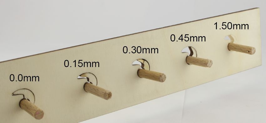
In this paper, we present “kerf-canceling mechanisms”.
Kerf-canceling mechanisms replace laser-cut bearings, slid-
ers, gear pairs, etc. Unlike their traditional counterparts,
however, they keep working when manufactured on a differ-
ent laser cutter and/or with a different kerf value. Kerf-can-
celing mechanisms achieve this with by adding an additional
wedge element per mechanism (such as the moon-shaped in-
set in the bearing in the center of Figure 1).
We also present a software tool called KerfCanceler that lo-
cates certain types of mechanisms in SVG files and replaces         Figure 2: (a) When fabricated on a machine with smaller kerf,
them with their kerf-canceling counterparts. The resulting          this bearing gets too tight. This causes friction or even prevents
models function irrespective of the laser cutter or kerf values     users from inserting the axle. (b) On machines with wider kerf,
                                                                    bearings are subject to slack, potentially causing adjacent
they are fabricated on—making these models particularly
                                                                    mechanisms to jam.
suitable for sharing.
                                                                    Unfortunately, tuning tends to get lost when manufacturing
CONTRIBUTION, BENEFITS & LIMITATION
In this paper, we make three contributions. First, we present       a model on a different machine—as is the case when sharing
                                                                    a model, and the resulting models are again subject to slack
an analysis of why variations in kerf cause laser-cut mecha-
nisms to fail. Second, we address the problem by presenting         and/or jamming.
kerf-canceling alternatives to three elementary classes of          This problem affects a wider range of mechanisms, including
mechanisms. Third, we present a software tool that locates          three of the four primary types of mechanisms with moving
mechanisms in laser-cut models semi-automatically and re-           parts [1] shown in Figure 3. Red highlighting indicates areas
places them with kerf-canceling equivalents. The tool ac-           where kerf-related problems occur.
cepts 2D cutting plans (svg) as input and produces output in
the same format, allowing the resulting cutting plans to be
stored and shared using existing infrastructure.
Lastly, the proposed workflow requires the designer of the
model to act (using kerfCanceler) as opposed to everyone
who tries to fabricate it, which is the case with the current
workflow where users manually calibrate the file to their la-       Figure 3: Three out of four elementary classes of joints [1] are
                                                                    subject to kerf-related issues. Susceptible surfaces are marked
ser cutter.
                                                                    in red. (a) The revolute pair includes mechanisms that operate
Our approach is subject to three limitations; however, kerf-        like the bearing shown before, (b) a prismatic pair allows a rod
canceling mechanisms are less robust than traditional mech-         with rectangular cross section to slide forth and back, and (c) a
anisms, they require additional space in the cutting plan, and      pair of gears. (d) Only cam/follower mechanisms remain unaf-
                                                                    fected, as they are spring-loaded.
they may affect the aesthetics of a model.
CHALLENGE: MECHANISMS SUSCEPTIBLE TO KERF
                                                                    While we focus on laser cutting, kerf issues consistently af-
In this section, we take a closer look at why traditional mech-     fect all subtractive fabrication methods, irrespective of the
anisms fail as the result of variations in kerf. Figure 2 illus-    quality of the machine and the approach presented in this pa-
trates this at the example of a bearing. In its simplest form, a    per applies to other types of machines as well, such as milling
bearing is a round opening.                                         machines.
                                                                    KERF-CANCELING BEARINGS
In order to work properly, a bearing should hold its axle in
                                                                    Kerf-canceling mechanisms, such as kerf-canceling bearings
place without causing it to jam. In Mechanical Engineering
                                                                    address this issue with the help of one additional component:
this is referred to as “loose fit” [16] and achieving it in a la-
                                                                    the crescent-shape inset shown in Figure 4a. The figure
ser-cut model requires the size of the opening to be tuned
                                                                    shows how the mechanism is assembled by inserting the in-
properly. Without proper tuning, a bearing that is too loose
                                                                    set and rotating it clockwise. This jams the inset, locking it
introduces slack. This slack tends to cause mechanical issues.
                                                                    in place. At this point, the rotation of the inset has reduced
In the focus adjustment mechanism shown in Figure 1, slack
                                                                    the diameter of the remaining opening. The specific design
causes the microscope’s rack and pinion mechanism to jam.
                                                                    of the inset, as discussed below, causes this opening to al-
                                                                    ways be of the same size, irrespective of the kerf value of the
                                                                    machine it was fabricated on.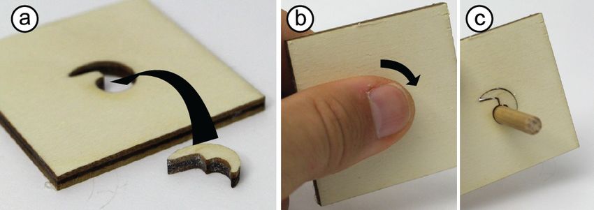
The inverter: The inverter is the shape on the inside of the
inset. The key idea behind the inverter is that it bears the
same shape as the jammer—but mirrored. Based on the jam-
mer translating size (= kerf) into rotation, the inverter trans-
lates rotation back into size. Since its shape is mirrored with
respect to the jammer, it does so inversely though, i.e., the
further it is rotated, the more it reduces the opening in its
Figure 4: Assembling the kerf-canceling bearing. center, i.e., the bearing. This allows it to keep the size of the
bearing constant. With other words, a larger kerf value
As illustrated by Figure 7a, the spiral inset consists of two makes the opening wider, but also leads to additional rotation
logical elements, which we call jammer and inverter. of the jammer, which in turn causes the inverter to narrow
The jammer: The jammer is the shape on the outside of the the opening further, canceling out the effect of kerf.
inset. To illustrate how it works, consider a wedge [12]. As
illustrated by Figure 5, a wedge-shaped inset in a wedge-
shaped cutout jams when slid towards the tapered side of the
cutout. If we increased kerf, the inset slides further—but ul-
timately it will jam just the same. Note that the distance the
inset slides is proportional to the kerf of the machine.
Figure 7: (a) The kerf canceling bearing consists of 2 key ele-
ments: (b) the jammer which is characterized by a self-similar
nautilus shape that jams in place when rotated and (c) the in-
Figure 5: (a) A wedge inset jams by sliding it to the right. A verter, which converts the rotation of the jammer back to a
larger kerf value removes the red region, (b) allowing the inset bearing, which ultimately holds the axle.
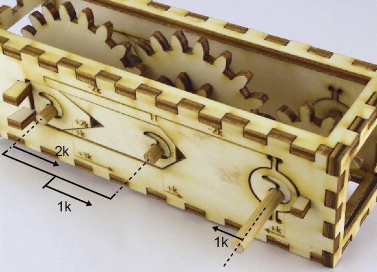
to slide further before it jams. As illustrated by Figure 8, kerf-canceling bearings produce
Applying a polar transformation to the wedge produces the the same fit, irrespective of kerf and thus irrespective of the
spiral inset we use in kerf-canceling bearings (Figure 6). The machine they were fabricated on. Even with a simulated kerf
spiral version jams when rotated. In analogy to the wedge, of 0.45mm the bearing continues to produce the desired fit.
the inset’s final orientation reflects the kerf value. This exceeds the most extreme typical kerf value in a laser
cutting survey by cutlasercut.com [10]. Even when executed
on a milling machine with a mill bit of 1.5mm, the axle fits
the resulting bearing well.
Figure 8: Kerf-canceling bearings fit their axle under variation
of a wide range of kerf (by eroding the model). Even when cut
on a milling machine with much more kerf.
Figure 6: (a) The kerf-canceling bearing. (b) when the model is
cut with more kerf, the inset gets smaller while the cutout gets
wider. (c) the resulting inset falls out (d), however the self-simi-
lar shape of the inset makes that it always jams when rotated in
place, even as kerf gets bigger.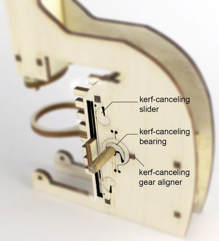
Technical details
To help readers replicate our designs, we now present the
necessary technical details. We begin with the jammer. The
slope (s) is constant s = dr/dθ, the radius thus decreases pro-
portional to the angle θ from the center of the spiral. A given
point p0 on the contour of the jammer has a radius r0 and cor-
responding angle θ0. Another point on the same contour pθ
rotated by an angle of θ from r0 is thus rθ = r0-s*θ. We can
rewrite this to calculate the angle θ between two points, given
their radii: θ = (r0-rθ) /s.                                               Figure 10: (a) Kerf in a laser cutter is slanted. (b) when cut from
                                                                           the same side, edges poorly align (c) Flipping one side of the
The cutout and the jammer have the same slope s. Because                   plate results in a better fit. (d) Our software tool flips insets by
of kerf, the radius of the inset is k shorter (the red zone in             default to support this.
Figure 7b). There is a point on the inset with r0-k which, be-             KERF-CANCELING SLIDERS
fore jamming the inset, is aligned with p0. This point jams in             We have applied this concept of jammer and inverter to three
the contour where the radius cutout of the contour is r0-k. We             other types of mechanisms. Sliding mechanisms can be or-
insert r0-k as rθ in the formula derived above, and find that              thogonal or parallel to the surface of the model. In both
the angle θ is (r0-r0-k) /s = -k/s.                                        forms, the kerf canceling variant narrows the slit to counter-
The inverter has the same slope as the jammer, flipped (-s).               act kerf. Figure 11 shows kerf-canceling sliding mecha-
A point on that spiral can be calculated using:                            nisms. We use the principle of the straight wedge (Figure 5).
rinv,θ = rinv,0 + s*θ (Figure 7c). If we substitute θ with -k/s, we        The V shape between the two prongs of the inset lets it slide
get: rinv,θ = rinv,0 + s*(-k/s), this simplifies to rinv,θ = rinv,0 - k.   down to narrow the slit, a spiral wegde on top locks it in place
Kerf eroded the inset by k, so the radius from the center is k             as shown in Figure 11c.
longer for every point, this results in: rinv,θ = rinv,0-k+k or rinv,θ     The parallel slider is narrowed down by pushing a thin spring
= rinv,0. We conclude that the kerf added, combined with the               towards the slit. The self-similar nautilus wedges responsible
jamming of the inset results in a bearing of constant size.                for this are jammed in the surface and push the spring by 1x
                                                                           kerf from both sides.

Figure 9: (a) The inset has to span 180 degrees; however, kerf
makes it shorter. (b) By extending the spiral and making the tip
less sharp, the inset remains stable as kerf increases.
Kerf affects the length of the spiral inset, i.e., if kerf gets
wider, the inset gets shorter. To prevent it from spanning less            Figure 11: Kerf-canceling sliders (a-d) orthogonal, (e-g) and
                                                                           parallel. (a) The cutout between the prongs lets the shape slide
than 180° (Figure 9a), we extend the spiral further than just
                                                                           down by 2x kerf. (b) The spiral wedge on top locks it in place.
180°, by extending it on top (Figure 9b). To make the length               (e) For parallel sliders we insert two simple nautili next to a thin
of the inset less susceptible to changes in kerf, we round off             bar (f) the bar gives way as the nautili push by 1x kerf.
the bottom tip.
                                                                           KERF-CANCELING GEARS
For even better results, we manufacture the inset mirrored.                The kerf-problem with gears (and other mechanisms that in-
As illustrated by Figure 10, kerf in laser cutting results in a            terlock into each other) is that kerf makes them smaller, re-
non-straight edge. By mirroring the inset in the cutting plan,             sulting in teeth of one gear to be further away from those of
it gets cut from the other side, resulting in a part with the              another. To cancel out kerf, we push them towards each
slanted edge facing the opposite direction. This allows the                other. As shown in Figure 12, we cut a slit around the bearing
slanted edge of the inset to line up with the slanted edge of              of one gear and add a wedge next to it to push it towards the
the rest of the mechanism (Figure 10c). An informal valida-                other gear. The resulting translation makes the gears mesh
tion shows that flipping the inset increases the friction force            again. To keep the bearing in the same plate as its surround-
by about 60%.                                                              ing we do not cut it out all the way but keep it connected to
                                                                           the plate with a thin (flexible) extension.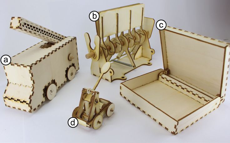
Reuse in fabrication
                                                                   SpringFit [21] investigates the machine-dependency prob-
                                                                   lem and presents cantilever-based springs as a replacement
                                                                   of the problematic press-fit joints and mounts. By extending
                                                                   this with our tool, a wide range of portability problems are
                                                                   handled.
                                                                   PARTS [14] is a framework that makes functional entities in
                                                                   models parametric, which enables models to be portable
Figure 12: Assembly of the kerf-canceling gear pair. It jams the   across a range of use contexts. Similarly, Grafter [20] allows
gears towards each other to compensate for the shorter teeth (a)   users to recombine elements from multiple parent models
Insert the bearing wedge, (b) then add a straight wedge next to    found in online repositories into a new device. It does so by
it, which (c) jams the whole assembly to the right.                keeping mechanisms together and joining them with each
Multi-stage gearboxes by combining mechanisms                      other. This makes the mechanical design portable across
The kerf-canceling mechanisms described above can be               models.
combined to implement more exotic kerf-cancellation tech-          Tolerances in fabrication
niques. Figure 13 shows a combination of various wedges to         The problem of tolerancing in the manufacturing process is
form a complex mechanism: a kerf-canceling 3-stage gear-           widely acknowledged. Zhang et al [22] state the importance
box. Both pairs of gears have to be moved towards each             of this problem, and highlight the variety of causes of “pro-
other. A single pair of gears is solved by moving the axles 1x     cess variability” as: accuracy of the tools, setup errors, de-
kerf towards one another (Figure 11c). If we naively paired        formation of the machining system under external forces,
the right and the middle axles, the axle on the left would be      thermal deformation of the system, tool wear, measurement
3x kerf away from the middle.                                      error and impurity of the materials. These factors all contrib-
By nesting the gear pair on the left together with the middle,     ute to variations in kerf for laser cutting. Raising the point
they are both moved 1 kerf closer to the gear on the right.        that not just when switching to a different user/machine the
Within the nested pair, the left gear is moved 2x kerf closer      kerf may be off, but even within the same machine, kerf in-
to the middle gear. The nester corrects kerf equivalent to the     variant solutions would benefit the user strongly.
angle of the tip: the angle of the left wedge is 2x as narrow      Geetha et al. [1] as well as the aforementioned work by
as the angle of the middle one making it correct 2x kerf as        Zhang et al [22] tackle the tolerance problem by optimizing
opposed to the 1x of the nested pair. When compared to the         the allocation of tolerances within the assembly. Hong et al
same gearbox with 0.3mm kerf, the normal one jams fre-             [15] refer to this approach as tolerance synthesizing, which
quently whereas the kerf-canceled one runs fine.                   comes closest to presenting a way to handle tolerance issues
                                                                   as opposed to analyzing them. Most research into tolerancing
                                                                   however, focuses on analyzing the tolerance issues and mod-
                                                                   eling these to allow engineers or designers to handle them by
                                                                   tuning the models (e.g. work on 3D revolute joints [2] or
                                                                   linkage systems [17]). In particular within the field of me-
                                                                   chanical design for haptics these analysis and optimization
                                                                   methods are widely used [1]. Carrino et al [8] took tolerance
                                                                   analysis and synthesis a step further by integrating it into an
                                                                   expert system for mechanical designers.
                                                                   In mechanical engineering, the Robust Design Methodology
                                                                   [3] aims to reduce noise in the manufacturing process. Their
                                                                   research typically focuses on process design, we extend this
                                                                   notion towards machine invariant fabrication. Downey et al
                                                                   [11] propose what they call smart features that are more ro-
                                                                   bust to tolerances using setscrews and adjustable mecha-
       Figure 13: A kerf-canceling multi-stage gearbox.            nisms. We push this further by having self-adjusting mecha-
                                                                   nisms that work right away (no configuring or setting re-
RELATED WORK                                                       quired).
Our work builds on research into reuse in fabrication, toler-
ances in fabrication, drivers/slicers for laser cutting, compli-
ant mechanisms and strategies users use to handle kerf now-
adays.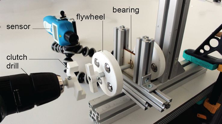
“Drivers/slicers” for laser cutting                                THE SOFTWARE TOOL: KERFCANCELER
In 2D publishing, portability has largely been solved by de-       Our software tool, kerfCanceler, converts traditional mecha-
veloping drivers, a software tool that takes in a generic model    nisms in 2D cutting plans to kerf-canceling equivalents. The
(e.g. PDF) and then configures it into a low-level protocol        tool takes the commonly shared SVG format as input and
for the specific printer at hand. In 3D printing, a similar pro-   produces output in the same format, allowing users to share
cess takes place where STL (or 3MF etc.) files are sliced with     the result in existing pipelines/repositories. The software is
a machine-specific configuration into a g-code file that then      designed to minimize redundant and uninspiring work for the
runs directly on the printer.                                      designer of the model. It automatically guesses the locations
                                                                   and types of mechanisms and then allows users to fix if
In order to achieve a similar workflow for laser cutting, one
                                                                   needed.
would have to make a parametric model (e.g., using
OpenSCAD (openscad.org) or OnShape (onshape.com).                  Walkthrough: converting the microscope of Figure 1
When later exported to 2D for cutting, the points where fit        As shown in Figure 14, the conversion starts by loading a 2D
matters can be handled by exporting for a specific laser cut-      cutting plan into the tool, here the microscope from Figure 1.
ter. 3D editing systems for laser cutting that export 2D ge-       The menu on the left offers 8 tools, three modify revolute
ometry are inherently parametric (e.g. Kyub [5] for finger         pairs (bearings, mounts and gear pairs), two tools for pris-
joints, CutCAD [13] for flat joints in general, and FlatFitFab     matic pairs (orthogonal and parallel sliders), one utility to
[9] for cross joints). With these systems users do not share       define the material thickness, a tool to remove suggestions
the 2D cutting plans, but the 3D models. The conversion to         and a tool that calls the algorithm of springFit [21] to make
2D cutting plans then takes place in the local context of the      joints kerf-invariant.
downloading user, allowing that user to generate cutting
plans for their local machine’s kerf. In practice, people do
not share those high-level descriptions, rather they share
SVGs as anyone can open and cut them (without having ac-
cess to the, typically proprietary, 3D software).
Compliant Mechanisms
Compliant mechanisms have the benefit that they do not con-
sist of separate parts that move with respect to one another,
but instead movement happens within the part. Trease et al
[19] compared large displacement compliant mechanisms in
this context. Their studied mechanisms would require a re-
design of the entire model or are limited in the motion range.
One exception, which is not limited in motion range, would
be the compliant revolute joint by Canon et al [7]. It would
be a candidate for bearing mechanisms albeit at a cost of          Figure 14: Converting the microscope model of Figure 1.
large changes to the model, including modifications to the         KerfCanceler classifies polygons when a new cutting plan is
non-laser-cut part (shaft that rotates in the bearing). We thus    loaded (identifying rotary mechanisms with 93% accuracy,
consider this outside the scope of mechanisms that could be        see section „Software Evaluation of kerfCanceler”). It auto-
integrated in off the shelf models, but we would highly rec-       matically inserts kerf-canceling mechanisms. In this exam-
ommend including such compliant mechanisms when mod-               ple, kerfCanceler added 9 mechanisms automatically.
eling objects from scratch.
                                                                   Kerf-canceling mechanisms require more space than their
Handling kerf                                                      traditional counterparts, they can intersect with existing ge-
The default process to handle kerf in practice is to measure       ometry in the cutting plan. KerfCanceler detects such cases
the kerf of your machine and tweak the file accordingly. Un-       and highlights them in red.
fortunately, it is not clear how much kerf and fit the original
model already contained and users have to repeat the meas-
urement for different materials or moments of cutting. Our
proposed solution puts the effort on the person sharing the
file once, to then let other users reliably reproduce the model
on their machines. In the context of mechanisms, a valid al-
ternative is to use spring loaded mechanisms as these are not
as vulnerable to small variations. Or add little spikes in a       Figure 15: The user removes a kerf-canceling mechanism in-
bearing which wear/break off when assembling to match the          serted by kerfCanceler (b) With the “remove mechanism” tool
shape of the shaft. Both spring loading and spikes add fric-       selected; the user clicks on a falsely labeled mechanism. (c) By
                                                                   default, all cutouts with the same diameter now have the mech-
tion to the mechanisms and risk creating misalignments.
                                                                   anism suggestion removed (shown in green briefly to indicate
While elegant and simple solutions, we think kerf-cancela-         the change).
tion is the more reliable approach here.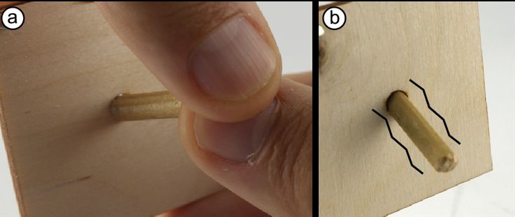
The microscope has three circles which are glare-holes, but          Classification and Conversion Algorithm
kerfCanceler guessed them to be bearings. The user removes           The algorithm to enable the workflow above proceeds in two
the suggestion as shown in Figure 15b, which reverts them            automatic steps. First, it pre-processes the cutting plan at
back to the original circular cutout. kerfCanceler recognizes        hand to identify mechanisms. Second, it replaces these mech-
that all three circles are the same size, so the user overrides      anisms with kerf-canceling equivalents.
them in a single click. If the user only wants to modify a sin-      Pre-processing
gle entity, it is possible to turn off “group edit”.                 KerfCanceler normalizes the SVG by breaking all SVG ele-
                                                                     ments into line segments. This removes ambiguities (e.g.
                                                                     polylines and paths that do the same thing but are defined
                                                                     differently) or document properties like layers that don’t in-
                                                                     fluence the laser cutting.
                                                                     KerfCanceler runs a parts vs cutout detection. It sorts all
                                                                     closed polygons by size. It checks if there is a larger polygon
                                                                     within which the given (smaller) polygon is enclosed and
                                                                     continues to do so until all are checked. It assumes that the
                                                                     outer cuts are outlines of parts and the inner ones are scrap.
Figure 16: (a) Users add sliding mechanisms manually, using          As shown in Figure 18, the user’s attention is pointed to-
the “slider tool” (b) KerfCanceler creates a kerf-canceling ver-     wards the content kerfCanceler assumes to be relevant. The
sion of that slider (c) both similar cutouts in the model are con-
                                                                     outlines of the parts are greyed out and the cutouts are high-
verted at once.
                                                                     lighted (typically the outlines of parts are not mechanisms).
Sliding mechanisms are rare and hard to identify correctly
(any polygon could be a cutout for a sliding mechanism).
Based on the principle of good guesses with little fixing,
KerfCanceler does not automatically place these. As shown
in Figure 16, users apply the “slider tool” to manually turn a
polygon into a sliding mechanism.

Figure 17: KerfCanceler extends a bearing with the gear tool         Figure 18: A model presented to the user (a firetruck). All out-
to compensate for the increased distance between the pinion          line geometry is greyed out to put the users’ emphasis on the
and the rack as a result of kerf.                                    mechanisms guessed by KerfCanceler.

The microscope contains a gear (aka pinion), which meshes            KerfCanceler iterates over the inner geometry to find mech-
with the rack. The “gear tool” allows users to align these. It       anisms. Revolute pairs (e.g. bearings, gears, wheels, cam/fol-
inserts the kerf-canceling mechanism around the already ex-          lowers) manifest themselves as circles in the model. Kerf-
isting bearing (as shown in Figure 17b). Initially, the gear is      Canceler groups circles by diameter. As shown in Figure 19,
pushed from the right, by clicking repeatedly, the user rotates      when two similar groups occur, it assumes the group with
this to match the intended orientation. In the first four clicks     smaller diameter is press-fit and the other group is loose fit.
it rotates by 90-degree steps. After that, granularity goes up.
In a last step, the user calls the springFit [21] algorithm to
make joints and mounts kerf invariant. It extends the same
data structures as kerfCanceler. We modified the algorithm
to not place springs when they overlap with a mechanism
(and nullify the fit) as the springFit springs tend to occur in
abundance. In some models this requires manual fixing.
This process takes a few minutes, and results in an SVG that
is fully kerf independent. The model will reproduce on any           Figure 19: These circle cutouts in the firetruck are of similar
machine when the user shares it with others.                         size. In the entire fire-truck model, one category turned out to
                                                                     be around 5.05 and one around 4.80mm, KerfCanceler assumes
Once the model is cut, the user jams the insets in place (be-        the small opening is press-fit opening and the other one loose fit
fore assembling the model) and continues to assemble the             (it thus placed two different mechanisms).
model in a regular laser cutting workflow.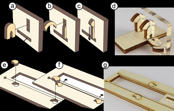
Replacing mechanisms with kerf-canceling counterparts                 TECHNICAL   EVALUATION:   HOW   WELL                         DO
KerfCanceler then places kerf-canceling mechanisms. At the            KERF-CANCELING MECHANISMS PERFORM?
positions where it assumed loose or press fit mechanisms, it          We hypothesize that kerf-canceling mechanisms are compa-
inserts the correct version. For every circular cutout, it            rable in performance to the original mechanism under default
caches three alternatives shown in Figure 20a-c: the original         kerf, and that with increased kerf, the kerf-canceling mecha-
circle, a press-fit mount based on cantilever springs [21] and        nisms outperform the original. We evaluate this by measur-
a kerf-canceling loose-fit bearing. It displays the one it            ing the friction and the play of the mechanism and compare
guesses to be the right version. Because these alternatives are       that to plain bearings, while varying kerf.
generated before the user touches them, it allows for interac-        We measure friction by spinning an axle with 2 flywheels on
tive response times in the web UI.                                    the side held in the sampled bearing, we start at 1300rpm
                                                                      (=136.14 rad/s) and measure how long it takes until the shaft
                                                                      stops spinning as a result of angular friction.
                                                                      We measure the tilt angle of the axle within each of the sam-
                                                                      pled bearings. We take a photograph with a fixed camera
                                                                      from the side of the bearing, tilt the axle up and down and
                                                                      capture both extremes. The angle between these corresponds
                                                                      to the maximum range of play.
Figure 20: Possible modifications of a circle cutout. (a) The orig-   Test setup
inal circle (b) a circle used as a mount (press-fit) (c) the circle   We mount the bearing with an 8mm aluminum axle. We at-
used as a kerf-canceling bearing and (d) the same as c but            tach a 3D printed flywheel with 4x 33g steel balls inside, to
pushed to the right by “kerf” using the wedge on the left, for
                                                                      both ends of the axle. The shaft is powered using a Bosch
gears.
                                                                      drilling machine via a simple clutch. The total inertial mo-
KerfCanceler checks for intersections with the model during           ment of the flywheels is 17.4x10⁻⁵ kgm2. We use the Peak-
pre-processing. It uses the shape of Figure 20c overlaid by b.        tech 2795 contactless rotation sensor to measure the rotation
If this intersects with the rest of the SVG model, the mecha-         speed. We then calculate the frictional Torque (T) using this
nism shows up in red, otherwise in blue. It does not use the          basic formula:
larger kerf-canceling gear-bearing of Figure 20d as this is a
rare case and would produce many false positives. When the            T=I*a
user later on inserts a gear-pair mechanism, kerfCanceler             In which a is the angular acceleration (initial rotation (rad/s)/
checks the intersections locally resulting in slightly longer         time (s)) and I the moment of inertia (kgm2).
processing time (up to a second).

Figure 21: The placement of wedges for a sliding mechanism,
(a) half of the edges of the cutout get a kerf adjusting wedge. (b)                  Figure 22: Experimental set-up.
The same works for non-rectangular cutouts. There is more
                                                                      Test pieces
than 1 possible placement for each wedge (see dotted lines).
KerfCanceler, excludes all that cause intersections and picks         We compare the baseline (a plain bearing) to the kerf-can-
the best solution.                                                    celing bearing. All pieces were cut out of 4mm plywood and
                                                                      we simulated kerf from 0 to 0.4mm in 0.1mm increments.
For guided sliding mechanisms, the wedges do not replace              These kerf values we adjusted for the laser cutter used, so
the original polygon, but line up on the sides. As shown in           0mm kerf means the bearing fully touches the axle. We re-
Figure 21, kerfCanceler places two wedges on each edge. It            peated each experiment 3 times and report the average value
places the wedges as far apart from each other as possible to         to compensate for noise.
minimize the risk of jamming the slider. For short edges, it
places one wedge in the middle of the edge.                           We used a Trotec speedy 360 flexx laser cutter with a kerf of
                                                                      0.15mm. To reproduce this experiment, we have attached a
                                                                      test piece in the appendix of this paper.
Results                                                           SOFTWARE EVALUATION OF KERFCANCELER
As shown in Figure 23, Kerf-canceling bearings demon-             To validate the utility of our software, we ran it on 20 models
strated constant performance across variations in kerf (be-       found online. For each model, we measured what percentage
tween 3.1 and 3.4 mN). Kerf heavily affected the plain bear-      of mechanisms were identified automatically and how many
ing’s performance. Already at a kerf variation of 0.1mm the       interaction steps were required to modify the mechanisms.
friction went up substantially (4.7 mN). And in particular        We also measured the time it took to do this.
when reducing the kerf further, the bearing essentially got
                                                                  The models in Figure 25 are a subset of the 20 test models
stuck as friction went up by a factor of more than 10. (40.6
                                                                  which we fabricated to confirm that the generated kerf-can-
mN).
                                                                  celing mechanisms work.

Figure 23: Results of the friction test. Kerf-canceling based
bearings perform stable across kerf variations as opposed to
plain bearings.                                                   Figure 25: Models of the test set we fabricated on our laser cut-
                                                                  ter with increased kerf.
Below are the results of the play analysis. For the plain bear-
ing, the play increases roughly linearly with the kerf. The       KerfCanceler achieved a 93% recognition rate for the rotary
play for the kerf-canceling bearings remained stable.             mechanisms in the models. It identified false positives in 5
                                                                  models, which contained engraved (decorative) circles, these
We found that strong vibrations (e.g. by accidentally misa-       were falsely identified as mechanisms.
ligning the drill bit) can cause the inset to come out. For
mechanisms that are expected to be exposed to such forces,        We used the UI to intervene with 2-21 (9 on average) over-
we recommend adding a dot of glue before assembling the           rides of the initial guessed mechanisms. Six models worked
mechanism.                                                        based on the guessed mechanisms alone. The “group edit”
                                                                  tool reduced the number of edits in most models. Pre-pro-
                                                                  cessing of models took on average 5.87ms of time. It took
                                                                  66s of manual work per model to convert, for a user who
                                                                  knows the model’s functionality.
                                                                  Six models failed to convert. Three of them had too little
                                                                  physical space in the model to insert the kerf-canceling
                                                                  mechanisms. Four models contained lines that were intended
                                                                  to be engraved, which caused intersections. One model
                                                                  showed both problems. These intersections won’t break the
                                                                  mechanism but may affect the aesthetics of the model de-
                                                                  pending on how meaningful the original engravings were.
                                                                  So, in total 17/20 models were converted using our tool with
                                                                  a laser cuttable result.
Figure 24: Results of measuring play of the bearings. The kerf-
canceling bearing remains relatively stable, while play for the   We conclude that many models online can be converted to
plain bearing almost linearly relates to increasing kerf.         become kerf-canceling with only up to three minutes
Discussion                                                        (one minute on average) of user effort.
Kerf-canceling bearings demonstrate constant performance
independent of the kerf, both when it comes to the play and
the friction of the mechanisms. While plain bearings only
perform reliably in a narrow range of kerf. We thus conclude
that our bearings serve well as kerf-canceling mechanisms.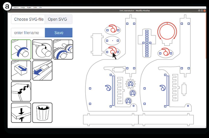
CONCLUSION AND PORTABLE LASER CUTTING                               REFERENCES
In this paper, we demonstrated how to create kerf-invariant         [1] Aftab Ahmad, Kjell Andersson, and Ulf Sellgren. "An
laser cut models with the help of kerf-canceling mechanisms.            optimization approach toward a robust design of six
We also presented a software tool that replaces problematic             degrees of freedom haptic devices." Journal of Mecha-
mechanisms in 2D cutting plans with kerf-canceling equiva-              nical Design 137, no. 4 (2015): 042301.
lents. The resulting cutting plans remain valid across ma-          [2] Narendra Akhadkar, Vincent Acary, and Bernard Brog-
chines and kerf values, which, for example, allows users to             liato. "Multibody systems with 3D revolute joints with
buy a new laser cutter without invalidating cutting plans cre-          clearances: an industrial case study with an experi-
ated earlier.                                                           mental validation." Multibody System Dynamics 42, no.
Zooming out, kerf-canceling mechanisms address one facet                3 (2018): 249-282.
of a larger challenge, i.e., the challenge of portability. Today,   [3] Martin Arvidsson, and Ida Gremyr. "Principles of ro-
the majority of laser-cut models are shared as 2D cutting               bust design methodology." Quality and Reliability En-
plans—and these are inherently machine-specific. This is                gineering International 24, no. 1 (2008): 23-35.
problematic, as this gets in the way of collaboration and shar-
                                                                    [4] Patrick Baudisch and Stefanie Mueller. 2017. Personal
ing, which rely on people’s ability to reproduce other users’
                                                                        Fabrication, Foundations and Trends in Human–Com-
models, e.g., for the purpose of remixing them.
                                                                        puter Interaction: Vol. 10: No. 3–4, pp 165-293.
In the long run, we as a field should try to move away from             http://dx.doi.org/10.1561/1100000055
2D cutting plans and towards more abstract representations          [5] Patrick Baudisch, Arthur Silber, Yannis Kommana,
that are merely instantiated for the machine at hand. 3D edi-           Milan Gruner, Ludwig Wall, Kevin Reuss, Lukas Heil-
tors for laser cutting are an important first step in this direc-       man, Robert Kovacs, Daniel Rechlitz, and Thijs Rou-
tion (such as FlatFab [9] and Kyub [5]). In the future, it              men. 2019. Kyub: a 3D Editor for Modeling Sturdy La-
would be good to see such systems not just represent a                  ser-Cut Objects. In 2019 CHI Conference on Human
model’s shape, but also the logic behind it. In 3D printing             Factors in Computing Systems Proceedings (CHI
this has already started to happen—with modern file formats             2019), May 4–9, 2019, Glasgow, Scotland, UK. ACM,
that contain mechanical metadata such as 3mf. For laser cut-            New York, NY, USA.
ting, systems that treat laser-cut objects as 3D models [9],            https://doi.org/10.1145/3290605.3300796
[5], [13] are a great first step in this direction.
                                                                    [6] Leah Buechley and Hannah Perner-Wilson. 2012.
Still, as of today, 2D cutting plans are the most common for-           Crafting technology: Reimagining the processes, mate-
mat for exchanging models and will most likely remain rele-             rials, and cultures of electronics. ACM Trans. Com-
vant legacy for decades to come. We thus have to deal with              put.-Hum. Interact. 19, 3, Article 21 (October 2012),
them. We think of kerf-canceling mechanisms as one facet                21 pages. DOI:
in the bigger agenda of transitioning from 2D cutting plans             https://doi.org/10.1145/2362364.2362369
to machine-independent formats.
                                                                    [7] Jesse R. Cannon, and Larry L. Howell. "A compliant
To illustrate this idea of kerf-invariant (and maybe one day            contact-aided revolute joint." Mechanism and Machine
portable) 2D cutting plans, we combined our tool KerfCan-               Theory 40, no. 11 (2005): 1273-1293.
celer with a tool that makes joints and mounts kerf-invariant       [8] Giovanni Moroni Carrino, Wilma Polini, and Quirico
(springFit [21]). As shown in Figure 26, we pipe SVG files              Semeraro. "Machining planning for tolerance synthe-
through both tools, resulting in mechanisms being replaced              sis." Machining science and technology 7, no. 3
and then mounts and joints being replaced. The resulting                (2003): 333-347.
model now assembles and works reliably irrespective of the
laser cutter it is fabricated on.                                   [9] James McCrae, Nobuyuki Umetani, and Karan Singh.
                                                                        2014. FlatFitFab: interactive modeling with planar sec-
                                                                        tions. In Proceedings of the 27th annual ACM sympo-
                                                                        sium on User interface software and technology (UIST
                                                                        '14). ACM, New York, NY, USA, 13-22. DOI:
                                                                        https://doi.org/10.1145/2642918.2647388
                                                                    [10] CutLaserCut kerf manual http://www.cut-
                                                                        lasercut.com/resources/tips-and-advice/what-is-laser-
                                                                        kerf. Accessed January 2020.
                                                                    [11] Kris Downey, Alan Parkinson, and Ken Chase. 2003.
                                                                        An introduction to smart assemblies for robust design.
Figure 26: After making all mechanisms kerf-canceling, the              Research in Engineering Design 14, no. 4 (2003): 236-
“joint tool” automatically converts all joints to portable ones         246. DOI: https://doi.org/10.1007/s00163-003-0041-5
using the algorithm of springFit [21].
[12] Heinrich Dubbel, and B. J. Davies. Dubbel-Handbook [19] Brian Trease, Yong-Mo Moon, and Sridhar Kota. "De-
of mechanical engineering. Springer Science & Busi- sign of large-displacement compliant joints." Journal
ness Media, 2013. of mechanical design 127, no. 4 (2005): 788-798.
[13] Florian Heller, Jan Thar, Dennis Lewandowski, Mirko [20] Thijs Roumen, Willi Müller, and Patrick Baudisch.
Hartmann, Pierre Schoonbrood, Sophy Stönner, Simon 2018. Grafter: Remixing 3D-Printed Machines. In Pro-
Voelker, and Jan Borchers. 2018. CutCAD - An Open- ceedings of the 2018 CHI Conference on Human Fac-
source Tool to Design 3D Objects in 2D. In Proceed- tors in Computing Systems (CHI '18). ACM, New
ings of the 2018 Designing Interactive Systems Confer- York, NY, USA, Paper 63, 12 pages. DOI:
ence (DIS '18). ACM, New York, NY, USA, 1135- https://doi.org/10.1145/3173574.3173637
1139. DOI: https://doi.org/10.1145/3196709.3196800 [21] Thijs Roumen, Jotaro Shigeyama, Julius Cosmo Ro-
[14] Megan Hofmann, Gabriella Hann, Scott E. Hudson, meo Rudolph, Felix Grzelka, and Patrick Baudisch.
and Jennifer Mankoff. 2018. Greater than the Sum of SpringFit Joints and Mounts that Fabricate on Any La-
its PARTs: Expressing and Reusing Design Intent in ser Cutter. In Proceedings of the 32th annual ACM
3D Models. In Proceedings of the 2018 CHI Confer- symposium on User interface software and technol-
ence on Human Factors in Computing Systems (CHI ogy (UIST '19). ACM, New York, NY, USA, DOI:
'18). ACM, New York, NY, USA, Paper 301, 12 pages. https://doi.org/10.1145/3332165.3347930
DOI: https://doi.org/10.1145/3173574.3173875s [22] Luke Wallace, A fully lasercut kit 3D printer, on
[15] Hong, Y. S., and T. C. Chang. "A comprehensive re- https://hackaday.io/project/164156-lp3d-a-fully-la-
view of tolerancing research." International Journal of sercut-kit-3d-printer last accessed September 2019
Production Research 40, no. 11 (2002): 2425-2459. [23] Chun Zhang, and Wang Hsu-Pin. "Robust design of as-
[16] ISO, DIN. "286-1: ISO-System für Grenzmaße und sembly and machining tolerance allocations." IIE
Passungen." Grundlagen für Toleranzen, Abmaße und transactions 30, no. 1 (1998): 17-29.
Passungen (1990). [24] Amit Zoran. 2015. Hybrid craft: showcase of physical
[17] Pezzuti, E., R. Stefanelli, P. P. Valentini, and L. Vita. and digital integration of design and craft skills. In
"Computer-aided simulation and testing of spatial link- ACM SIGGRAPH Art Gallery (SIGGRAPH '15).
ages with joint mechanical errors." International jour- ACM, New York, NY, USA, 384-398. DOI:
nal for numerical methods in engineering 65, no. 11 http://dx.doi.org/10.1145/2810185.2810187
(2006): 1735-1748. [25] Amit Zoran and Leah Buechley. "Hybrid reassemblage:
[18] Ting, Kwun-Lon, and Yufeng Long. "Performance an exploration of craft, digital fabrication and artifact
quality and tolerance sensitivity of mechanisms." Jour- uniqueness." Leonardo 46, no. 1 (2013): 4-10. DOI:
nal of mechanical design 118 no. 1(1996): 144-150. https://doi.org/10.1162/LEON_a_00477You can also read