3D Robot Assisted Fracture Reduction
←
→
Page content transcription
If your browser does not render page correctly, please read the page content below
3D Robot Assisted Fracture Reduction

Ralf Westphal1 Thomas Gösling2 Markus Oszwald2 Jan Bredow2 Daniel
Klepzig2 Simon Winkelbach1 Tobias Hüfner2 Christian Krettek2 and
Friedrich Wahl1
1
    Institute for Robotics and Process Control, Technical University of
    Braunschweig, Muehlenpfordstr. 23, 38106 Braunschweig, Germany
    rwe@rob.cs.tu-bs.de
2
    Department of Trauma Surgery, Hannover Medical School, Carl-Neuberg-Str. 1,
    30625 Hannover, Germany goesling.thomas@mh-hannover.de

Abstract. Reduction in femoral shaft fractures may be difficult to achieve with
minimal invasive techniques. Malalignment and high intraoperative radiation
exposures can result. Our hypothesis is that robot assisted fracture reduction
may improve the quality of reduction while reducing the amount of radiation
exposure. In this paper we present a telemanipulator system for the robot
assisted reduction of femoral shaft fractures. The telemanipulated reposition
is performed with a 2D input device with haptical feedback based on 3D
imaging data which can be acquired intraoperatively. With this system, we
performed a test series to measure achievable reposition accuracies on artificial
broken human femur bones without soft tissues. Furthermore, we performed
first tests for the 3D reposition on complete human legs. The experimental
set-up and results are presented in this paper. We could show, that the 3D
telemanipulated reposition of such fractures is possible yielding very good
accuracies in an intuitive and efficient way. Robot assisted fracture reduction
has the potential to improve the reposition accuracy and furthermore reduce
the X-ray irradiation exposure to patient and OR staff.

1 Introduction
Fractures of the femoral (thigh bone) shaft are nowadays often treated with
a minimally invasive technique, called intramedullary nailing. The fracture
fixation is achieved internally by a so called intramedullary nail, which is
usually inserted from the hip end side of the leg into the bone’s medullary
cavity. This technique has proven high union rates between 90-99% with a low
incidence of infection [1, 2].
    However, several problems associated with this technique have been out-
lined in literature. E.g., the radiation exposure to the operating staff and to
the patient is quite high, especially during the process of reduction with av-
erage image intensifier usages between 158 and 316 seconds as recorded in
the open literature [1, 3]. A second well-known and meaningful problem is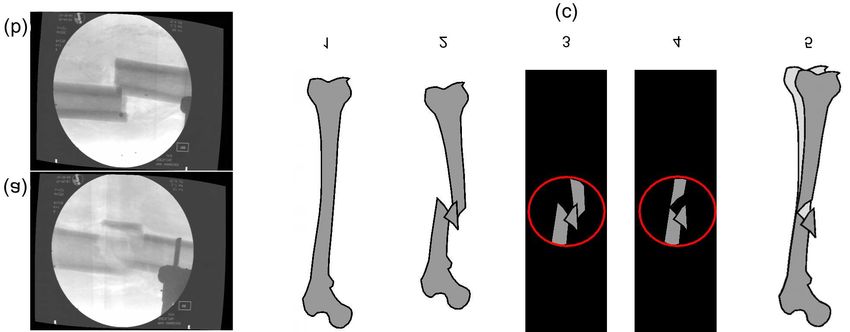
2       Ralf Westphal et al

Fig. 1. (a), (b) Two exemplary X-ray images of femur fractures in their position
before repositioning. (c) How the problem of a limited view during 2D fluoroscopy
based fracture reduction can lead to rotational misalignments in sagittal and frontal
plane.

the malreduction. Significant malalignment in the sagittal and frontal plane
differs between 2 and 18 percent [4, 5]. Correct rotation around the shaft axis
is difficult to achieve intraoperatively, as only 2D fluoroscopy is used for as-
sessment (see figure 1). Differences of more than 10◦ of rotation are recorded
with an incidence of more than 40 percent [5]. Malreduction leads to unphys-
iological conditions with consecutive reoperation in several cases [6]. Both
problems are related to difficulties in achieving and maintaining the correct
reduction. These problems are evident in the femur because of its tube-shaped
bony anatomy and its counteracting muscle strength.
    In our interdisciplinary working group of engineers and physicians, we are
investigating and evaluating methods to overcome these clinical problems, by
the use of robot assistance systems.

1.1 Previous Work
In our first studies, we evaluated the reposition performance of a telemanipu-
lated fracture reduction robot in a simplified laboratory set-up. We used CCD
cameras instead of X-rays for the fracture imaging and the reduction was per-
formed on plastic bones with artificial fractures without any soft tissues [7]
and counteracting forces. The results of these preliminary studies encouraged
us to further develop the method of robot assisted fracture reduction because
of its intuitive, well controlled, and gentle reposition procedure.
    Our second step was to transfer the laboratory set-up a step further to-
wards the real clinical environment. Using human specimens and the combina-
tion of X-ray imaging and navigation, we performed tests as close to clinical
practice as possible [8]. We could show, that robot assisted fracture reduc-
tion is possible in this environment yielding accuracies, which are as good as
achievable with conventional methods but conspicuously reduce the amount of
required X-ray irradiation time. Unfortunately the achieved reposition accu-
racy was not better than achievable with the conventional manual procedure
due to the poorer quality of the X-ray images, compared to CCD camera im-
ages. So one could conclude from these tests that telemanipulated fracture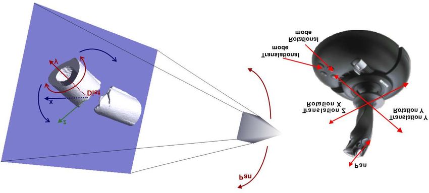
3D Robot Assisted Fracture Reduction        3

reduction based on 2D X-ray imaging is possible and conspicuously reduces
X-ray irradiation but does not improve the accuracy of reposition. Figure 1
shows some X-ray images from that test series, it can easily be imagined,
that the rotation around the bone axis is difficult to reconstruct, figure 1c
illustrates the problems arising for correctly reconstructing the bone segment
orientations in lateral views.
    In this paper, we present our set-up for telemanipulated, robot assisted
fracture reduction based on intraoperative 3D imaging of the fracture. The
results from a first test series are also presented and discussed in the context
of possible benefits for patients and surgeons from a robot assisted fracture
reduction procedure.

1.2 Related Work

Robot assisted reduction and fixation of femoral shaft fractures was first de-
scribed by Bouazza-Marouf et al [9]. They declared requirements for a reduc-
tion tool, but however, they did not publish any experimental results. While
there is a world wide copious work and research on many aspects of robot
assisted minimally invasive surgery, only few research is done in the field of
robotized fracture reductions.
    The group around L. Joskowicz performed research in the context of nav-
igated repositions of femoral shaft fractures [10]. But despite of a robot for
distal locking [11] they made no attempts for a robotized fracture reduction
procedure. Füchtmeier et al. [12] performed some basic experiments with robot
assisted reduction of femoral fractures. Warisawa et al. [13] are developing a
noninvasive robot system for femur shaft fracture reduction.

2 System Overview
Our telemanipulator system comprises standard commercial sub systems. As
manipulator we use the Stäubli RX 90 (Stäubli Tec-Systems, Faverges, France)
robot with its CS7B controller unit programmable in V+. Attached to the
robot’s hand is a force torque sensor (FT Delta SI-660-60; Schunk, Lauffen,
Germany). Intraoperative 3D imaging is achieved by the Siemens Siremobil
Iso C 3D (Siemens AG, Medical Solutions, Erlangen, Germany) fluoroscopy
device. For the 3D tracking of the fracture segments and for the registration
of the 3D image volume, we use an optical surgical navigation system (Vec-
torVision, BrainLAB, Munich, Germany). The input device, a force feedback
                    r              r
joystick (Microsoft°  , SideWinder°  ForceFeedback 2; Microsoft Corp., USA),
                                           r                                  r
is connected to a standard PC (Pentium°      4, 2.8 GHz) running Microsoft°
          r
Windows°    2000. All four sub systems (controller PC, robot controller, naviga-
tion system, and fluoroscope) are connected via a TCP/IP 100Mbit network.
Figure 2a illustrates this telemanipulator set-up.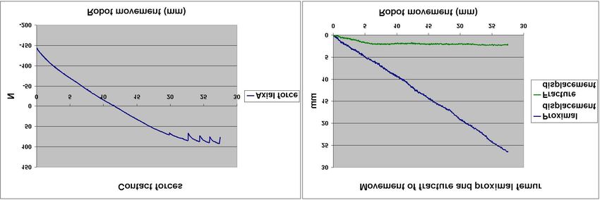
4 Ralf Westphal et al
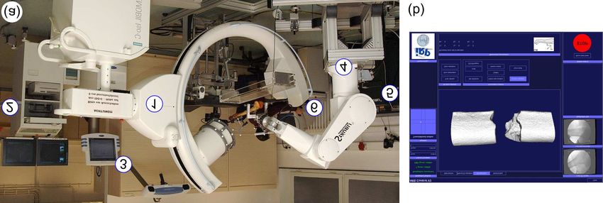
Fig. 2. (a) Telemanipulator system overview. 1: Fluoroscopy device. 2: Fluoroscopy
workstation. 3: Surgical navigation system. 4: RX 90 robot. 5: Robot controller unit.
6: Controller PC. (b) User interface of the controller program with a 3D scene of
the fracture region.
3 Telemanipulator Reposition in 3D
The process of 3D fracture reduction is separated into two steps. The first step
is the acquisition of the 3D data set and the reconstruction and registration
of a 3D surface model, which is subsequently used for displaying a 3D scene
on the controller PC. The second step is the reposition process itself.
At first, a 3D DICOM data set is acquired with the Siemens Iso C 3D. The
BrainLAB navigation system calibrates this data set by computing the rigid
transformation from the DICOM coordinate space to the Y DRB (dynamic
reference base of the optical navigation system) which is rigidly mounted to the
proximal (hip side) femur segment. The DICOM data set and the calibration
matrix are transferred to the controller PC. With a simple threshold based
segmentation method, the two major fracture segments are segmented and
3D surface models are reconstructed using the marching cube algorithm. The
controller PC finalizes the calibration by computing the rigid transformations
between the proximal 3D model and the Y DRB and the distal (knee side) 3D
model to which the T DRB is rigidly connected. The bone axis is computed
using an adapted kind of hough transformation, accumulating all possible
orientations of axes, perpendicular to the surface normals of the bone meshes.
See [14] for further details.
During the reposition process, the controller PC presents a 3D scene to
the surgeon where the 3D models of the proximal and distal fracture segments
are displayed accordingly to their real position as measured by the navigation
system (see figure 2b).
In our telemanipulator system, the complex 3D reposition problem is re-
duced to simpler 2D repositions. With a 2D input device, the surgeon can
manipulate the fracture intuitively within a 2D projection of the 3D scene.
This simplifies the spatial cognition required to successfully reduce fractures.
Using an additional switch at the joystick (see figure 3), the user can pan the
viewing direction around the bone axis, which enables him to examine and
manipulate the fracture from every desired angle. The coordinate system in
the distal fracture center (Dist) is the task frame i.e. tool center point for all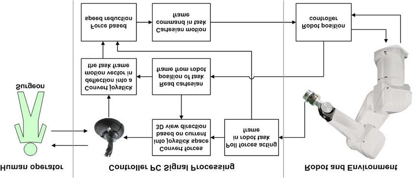
3D Robot Assisted Fracture Reduction          5

Fig. 3. Interaction possibilities for 3D fracture reduction with a 2D input device.

manipulations. It is oriented in a way, so that the y-axis is pointing knee wards
und the z-axis upwards. For translational motions, the mapping between the
joystick axes and the movement vector in task space is quite easy. The joy-
stick’s left/right axis is directly mapped to motions along the task frame’s
y-axis. The joystick’s front/back axis is mapped to a motion vector in task
space, which is created by the cross product between the viewing direction
and the task frame’s y-axis and so results in movements perpendicular to the
bone axis but inside the image plane. The mapping between the joystick and
the corresponding motion in task space can be expressed as a homogeneous
transformation matrix Joy TT ask . For rotational manipulations, the joystick’s
front/back axis is mapped to rotations about an axis parallel to the viewing
direction going through the task frame, whereas the left/right axis is mapped
to rotations about the task frame’s y axis, i.e. the bone axis. In this way all
required rotations in 3D can be intuitively achieved by rotations inside the
image plane.
    The force feedback capabilities of the joystick are used to reflect the forces
acting during contacts between fracture segments and the forces of soft tissue
interactions back to the user. With Joy TT−1 ask the forces measured in the task
frame can be transformed into the joystick’s force feedback axes to which they
are applied as constant force values scaled down to an appropriate range.
    Figure 4 illustrates the signal flow in our system. The force/torque sensor
is read out at a constant rate of 50 Hz and the joystick position with 30 Hz.
The desired feedback force of the joystick is also updated with a rate of 30
Hz. The force feedback control itself is accomplished directly inside the control
system integrated into the joystick. So we have a maximum delay for force
feedback of about 50 ms. Robot position set-points are generated at a rate of
10 Hz. Due to our non-real-time operating system and the non-deterministic
communication between the PC and the robot control unit, these rates are
not absolutely stable. However, due to the low stiffness of the environment
(see section 5) and the force based speed reduction (see next passage), the
system performed so far always safe and reliable.
6 Ralf Westphal et al
The force based speed reduction module of our processing chain prevents
the surgeon from applying forces that are too high for the robot and/or the
patient. If the angle between the force and motion vector is larger than 90◦
and the force value exceeds a predefined threshold, the motion vector will
be scaled down linearly with the force until it is set to zero when the force
exceeds a second critical force threshold. If the angle between the force and the
motion vector is less than 90◦ the motion command will be executed without
any scaling. In this way it is always possible to drive the robot safely out of
high force contact situations.
4 Experiments
As a first step in evaluating the performance of our 3D telemanipulator system,
we performed a test series with real human bones. The soft tissues of the bones
have been removed and a fracture has been placed by means of a three-point-
bending. We chose to use real bones and not plastic bone models because
of their more natural fracture surface, which conspicuously complicates the
process of reduction.
Four test persons repositioned one fractured bone several times in order to
perform a learning curve with this new telemanipulator system. Subsequently
they repositioned eight further bones each twice to perform the measurements
in order to evaluate the reposition parameters. We measured the reposition
time and the remaining translational and rotational deviations after the repo-
sition with respect to the unbroken reference state.
The set-up for our measurements is similar to the one we had used for our
2D test series previously published in [8]. First the two DRBs are mounted
to the unfractured bone and the relative transformation from the hip to the
knee side is recorded by the navigation system. Now the DRBs are removed
from their sockets to avoid displacements during fracture placement. A brake
point was sawn and the bone was broken by means of a tree-point-bending.
Subsequently the DRBs were remounted in the same position to the bone.
Fig. 4. Signal flow diagram of our telemanipulator set-up.3D Robot Assisted Fracture Reduction 7
After these preparation steps, the fracture was repositioned with the robot
used as a telemanipulator as previously described in section 3. When the
operator decides to finish the reposition process, the remaining deviations
from the original reference position was recorded.
The test set-up for reposition using human specimens is identical to the
one used for bare bones. By the time of writing this article, we have just
performed some initial reposition tests and have not yet completed a whole
test series. But these initial tests showed the problems arising due to forces
introduced by the soft tissue. A direct movement into the target position
is often not possible, due to forces exceeding a maximum threshold. So the
reposition strategy has to take some knowledge of how forces are introduced
by the soft tissue into account as well.
As stated in our conclusion below, the long term goal of the project is a
(semi-) automated fracture reduction by the robot. Of course, such an auto-
mated reposition should be force/torque guarded/guided. Therefore we exam-
ined the forces which act during common reposition situations, namely lateral
contact, lateral distraction, axial contact, axial distraction, and axial rotation
in contact. All these situations have been tested with intact soft tissues and
the proximal femur loosely fixed to the OR table with a noninvasive, non-
obstructive belt. We measured the forces and force/way ratios as well as the
displacements of the proximal femur due to the acting contact/distraction
forces.
5 Results
In the case of bare bones, we found out, that the learning curves for the
users are very steep. After a first introductory reposition, we couldn’t find
any further learning effects regarding reposition time and accuracy in all test
persons. And even throughout the rest of our test series, we couldn’t find any
learning effects. The achieved accuracies have been on a high level starting
with the first reposition. It turned out that such a 3D telemanipulated reposi-
tion procedure is very intuitive for the surgeons. So far, we haven’t performed
enough repositions with intact soft-tissues to measure learning effects in a
more realistic environment.
The experiments with bare bones achieved very good results with devia-
tions of less than two degrees and two millimeters in the mean. Compared to
clinical results achievable manually, these values are very satisfactory. Table 1
summarizes the results in detail.
Figure 5 illustrates some of our results obtained from force/motion mea-
surements on human bones with intact soft tissues. From the five contact
states mentioned before, we will limit the presentation here to the one with
the most conspicuous results, which is the movement from a slight distraction
of the bone fragments into contact. The diagram on the left presents the forces
acting in the direction of the bone axis which was moved into contact. It is re-
markable, that even though the bone moves from distraction into contact, the
force/motion profile is almost linear. The reason for this is the motion of the8 Ralf Westphal et al
Table 1. Results from telemanipulated femur repositions without soft tissues. N=64
Parameter Mean Std. dev. Min Max
Reduction time (min:sec) 4:34 2:31 2:00 12:57
Axial displacement (mm) 1.08 0.63 0.05 3.20
Lateral displacement (mm) 1.61 1.23 0.16 4.80
Varus/Valgus (axial torsion) (degrees) 1.37 1.39 0.02 5.82
Ante-/recurvature (front/back) (degrees) 1.42 0.84 0.19 4.04
External/internal rotation (degrees) 1.09 0.73 0.03 2.66
proximal femur part, caused by the continuous decrease of distraction forces
of the soft tissues. The overall stiffness of the system is about k = 9.5 N/mm.
The discontinuities at the end of the motion sequence are the result of some
jerky movements of the proximal leg due to the high forces.
The diagram on the right side of figure 5 illustrates, how motions of the
robot, i.e. the distal segment attached to it, affect the proximal femur and
the fracture displacement. Two points are of interest in this diagram. First it
is notable, that the major part of the robot motions is almost directly and
linearly reflected by the proximal femur. Secondly, from the fracture displace-
ment curve, we can state, that the contact is established after approximately
6 mm of robot motion, whilst the contact force measurement would establish
a contact at the zero-crossing after 11 mm. From this we can conclude that a
contact situation can not be identified by force analyses only. This has to be
taken into account when developing automated reposition procedures.
6 Conclusion and Outlook
The user interface for telemanipulation proved to be very efficient and intu-
itive. All test persons could reduce fractures successfully after a very short
training. The only difficulty stated by the surgeons is to remember the map-
ping between left/right alignment of the joystick and the corresponding rota-
tion around the femur shaft axis. But we think, this problem can be addressed
Fig. 5. Forces and displacements measured when moving from distraction into
contact along the bone axis.3D Robot Assisted Fracture Reduction 9
by simply visualizing the direction of rotation by means of some arcs within
the 3D scene.
The reposition results achieved during our tests (reposition time and accu-
racy) are very promising and show the potential of robotized fracture reduc-
tion based on 3D imaging data. However, in this study we only had two-part
fractures. It is still to be shown, how telemanipulated reductions perform if
there is no complete connection between the proximal and distal segment
(complex fractures, see figure 1c). Maybe only an automated computation of
the desired goal position as stated in our outlook can bring the desired ac-
curacy for those fractures. The next steps will be to evaluate the set-up on
fractures with intact soft tissues.
Due to the usage of a non real-time operating system and LAN communi-
cation with a standard commercial controller, the performance of our feedback
loop is not very efficient. The usage of a real-time operating system on the
controller PC in combination with the new robot control architecture devel-
oped at our institute [15], could conspicuously improve the performance of the
telemanipulator system. But however, the existing non-real-time system, as it
is currently used for our tests, performed absolutely reliable in all situations.
As even in contact situations the stiffness of the system is quite low and the
force based speed reduction module allows a careful approach to the contact,
the slow control rates of our system have not been a problem so far.
After finishing the experiments with telemanipulated repositions in human
specimens, the next step in our working program will be the automated frac-
ture reduction by the robot. Based on 3D CT data sets, we developed methods
to automatically compute the desired reposition parameters for fractured long
bones [14].
To conclude the robot assistance for this surgical procedure, we have al-
ready developed methods to support two more procedure task, which can
obviously benefit from robot assistance. The insertion of the intramedullary
nail at the hip side of the leg and the nail locking at the knee side. Both
methods use automated computer vision methods to enable a robotized drill
guidance. These methods are currently under testing in cadaver studies.
7 Acknowledgment
Research funding was provided by Deutsche-Forschungsgemeinschaft (DFG,
German Research Foundation). Our studies have been approved by the local
ethics commission. We would like to thank BrainLAB which supported us with
an interface to their navigation system. Furthermore we thank the department
of anatomy of the Hannover Medical School for making specimens available
for our experiments.
References
1. Kempf I, Grosse A, Beck G. (1985) Closed locked intramedullary nailing. Its
application to comminuted fractures of the femur. J Bone Joint Surg Am 67:10 Ralf Westphal et al
709-720
2. Krettek C, Schandelmaier P, Tscherne H (1998) Treatment of femoral shaft
fractures with an unreamed solid nail (UFN) and standard locking. Operat
Orthop Traumatol 6: 179-192
3. Sugarman ID, Adam I, Bunker TD (1988) Radiation dosage during AO locking
femoral nailing. Injury 19: 336-338
4. Grover J, Wiss DA (1995) A prospective study of fractures of the femoral shaft
treated with a static, intramedullary, interlocking nail comparing one versus
two distal screws. Orthop Clin North Am 26: 139-146
5. Prevot N, Charissoux JL, Fiorenza F, Arnaud JP, Pecout C (1998) Utilisation
d’un clou non fendu de Russel-Taylor pour la stabilisation des fractures du
femur. A propos de 57 fractures avec 30 etudes tomodensitometriques de la
rotation. Rev Chir Orthop Reparatrice Appar Mot 84: 33-40
6. Yang KH, Han DY, Jahng JS, Shin DE, Park JH (1998) Prevention of malro-
tation deformity in femoral shaft fracture. J Orthop Trauma 12: 558-562
7. Gösling T, Westphal R, Hüfner T, Faulstich J, Kfuri M, Wahl F, Krettek C
(2005) Robot-assisted fracture reduction: A preliminary study in the femur
shaft. Med Biol Eng Comput 43: 115-120
8. Westphal R, Winkelbach S, Gösling T, Hüfner T, Faulstich J, Martin P, Kret-
tek C, Wahl FM (2006) A Surgical Telemanipulator for Femur Shaft Fracture
Reduction. [in press] Int J of Medical Robotics and Computer Assisted Surgery
9. Bouazza-Marouf K, Browbank I, Hewit JR (1995) Robotic-assisted internal
fixation of femoral fractures. Proc Inst Mech Eng [H.] 209: 51-58
10. Joskowicz L, Milgrom C, Simkin A, Tockus L, Yaniv Z (1999) FRACAS: a
system for computer-aided image-guided long bone fracture surgery. Computer-
Aided Surgery , Vol. 3(6).
11. Shoham M, Burman M, Zehavi E, Joskowicz L, Batkilin E, and Kunicher Y
(2003) Bone-mounted miniature robot for surgical procedures: concept and clin-
ical applications. IEEE Trans on Robotics and Automation, Special issue on
Medical Robotics, R.H. Taylor guest editor. Vol 19(5): 893-901
12. Füchtmeier B, Egersdoerfer S, Mai R, Hente R, Dragoi D, Monkman G, Nerlich
M (2004) Reduction of femoral shaft fractures in vitro by a new developed
reduction robot system ‘RepoRobo’. Injury, Int J Care Injured 35: S-A113—S-
A119
13. Warisawa S, Ishizuka T, Mitsuishi M, Sugano N, Yonenobu K, Nakazawa T
(2004) Development of a femur fracture reduction robot Proc of the 2004 IEEE
International Conference on Robotics and Automation, New Orleans, U.S.A.:
3999-4004
14. Winkelbach S, Westphal R, and Gösling T. (2003) Pose Estimation of Cylindri-
cal Fragments for Semi-automatic Bone Fracture Reduction. In: B. Michaelis,
G. Krell (Eds.): Pattern Recognition (DAGM 2003), Lecture Notes in Computer
Science 2781, ISBN: 3-540-40861-4, Springer, Magdeburg, Germany: 566-573
15. Finkemeyer B, Kröger T, and Wahl FM (2005) Executing Assembly Tasks Spec-
ified by Manipulation Primitive Nets. Advanced Robotics, VSP and Robotics
Society of Japan, Vol. 19: 591-611You can also read