Design, Development and Experimental Realization of a Quadrupedal Research Platform: Stoch
←
→
Page content transcription
If your browser does not render page correctly, please read the page content below
Design, Development and Experimental Realization of a Quadrupedal
                                                                Research Platform: Stoch
                                                                 Dhaivat Dholakiya, Shounak Bhattacharya, Ajay Gunalan, Abhik Singla,
                                                              Shalabh Bhatnagar, Bharadwaj Amrutur, Ashitava Ghosal and Shishir Kolathaya

                                                                                                                                                     Carbon Fiber Plates
                                            Abstract— In this paper, we present a complete description
                                         of the hardware design and control architecture of our custom
                                         built quadruped robot, called the Stoch. Our goal is to realize
                                         a robust, modular, and a reliable quadrupedal platform, using                                                  3D Printed
arXiv:1901.00697v2 [cs.RO] 27 Feb 2019

                                                                                                                                                        Joints and Hubs
                                         which various locomotion behaviors are explored. This platform
                                         enables us to explore different research problems in legged
                                         locomotion, which use both traditional and learning based tech-
                                         niques. We discuss the merits and limitations of the platform
                                                                                                                                            Carbon Fiber Tubes
                                         in terms of exploitation of available behaviours, fast rapid
                                         prototyping, reproduction and repair. Towards the end, we
                                         will demonstrate trotting, bounding behaviors, and preliminary               Fig. 1: Left image shows the physical hardware of Stoch,
                                         results in turning. In addition, we will also show various gait              and the right image shows its rendered exploded view.
                                         transitions i.e., trot-to-turn and trot-to-bound behaviors.
                                           Keywords: Quadrupedal Robot, Legged Locomotion,
                                         Robot Design                                                                 the individual servo drives. The trajectory generator performs
                                                                                                                      reasonably well at control frequencies on many off-the-shelf
                                                                  I. I NTRODUCTION                                    servos (50 Hz). In addition to realizing robust gaits in the
                                            In the current state of research in robot locomotion,                     real hardware, the central pattern generator (CPG) based
                                         a beginner usually faces a stiff learning curve to design                    trajectory generator [2], [3], [4] also enables 1. Realization of
                                         and fabricate a robust and a reliable quadrupedal walking                    derived walking gaits like bound, walk, gallop, and turning
                                         platform. Crossing this barrier is not only limited by the in-               in hardware with no additional training, and 2. Smooth
                                         dividual’s capacity but also by the requirement of resources.                transitions from one type of gait to another. This is mainly
                                         Therefore, a robot which is simpler, modular, affordable,                    motivated by the various locomotion behaviors realized by
                                         easily repairable, and yet facilitating complex behaviors is                 [5], [2] in their custom hardware. These various behaviors
                                         largely preferred.                                                           are then composed together and tele-operated by a remote
                                            With a view toward realizing state of the art walking                     control device.
                                         controllers in a low-cost walking platform, we developed                        The paper is organized as follows: Section III details the
                                         a quadrupedal robot called the Stoch. This manuscript pri-                   design and hardware of Stoch. Section IV describes the
                                         marily serves as a detailed description of the hardware and                  software architecture, on-board compute platform, actuators,
                                         software design process and construction of this platform                    communication interfaces, and the sensory inputs. Section V
                                         (see Figure 1), which complements the results that were                      contains a detailed description of the control algorithm used.
                                         shown in [1]. This hardware features modular central body                    Finally Section VI describes the experimental results of
                                         and a five bar co-axial leg design. Which are fabricated                     Stoch demonstrating multiple types of gaits and the asso-
                                         using easily available off the shelf materials like carbon-fiber             ciated transitions.
                                         tubes and custom 3D PLA parts. Carbon fiber tubes, which
                                                                                                                                           II. R ELATED W ORK
                                         are strong and light, serve as the structural members and
                                         leg links. Similarly, the 3D printed parts, manufactured in-                    There have been multiple types of quadruped robots in
                                         house, act as the joints. The software consists of a real-time               varying sizes over the past ten years, namely, MIT Cheetah
                                         trajectory generator, which are then passed as commands to                   [6], Starl ETH [7], Spot mini [8], ANYmal [9], LaikaGo [10],
                                                                                                                      Minitaur [11] etc. Most of these works have mainly focused
                                               This work is supported by the Robert Bosch Center for Cyber Physical   on answering important questions on control and hardware
                                         Systems, Bangalore, India
                                               Dhaivat Dholakiya*, Shounak Bhattacharya, Ajay Gunalan, Abhik          design for walking, and have also demonstrated multiple
                                         Singla are with the Robert Bosch Centre for Cyber-Physical Systems,          types of functionalities both in simulation and experiments.
                                         IISc, Bangalore, India. E-mail: {dhaivatd, shounakb, ajayg,                  Despite their impressive results, it is important to note that
                                         abhiksingla}@iisc.ac.in.
                                               Ashitava Ghosal is with the Faculty of Mechanical Engineering,         these robots cost to the tune of minimum $30,000, are
                                         Bharadwaj Amrutur is with the Faculty of Electrical & Computer En-           expensive to manufacture, and also require advanced sensing
                                         gineering, Shalabh Bhatnagar is with Computer Science & Automa-              and actuation.
                                         tion, and Shishir Kolathaya is an INSPIRE Faculty Fellow at the
                                         Robert Bosch Center for Cyber Physical Systems, IISc, Bengaluru, India          There are also quadrupeds that are less resource intensive
                                         {shalabh,amrutur,asitava,shishirk}@iisc.ac.in                                such as Tekken [12], Cheetah-cub [3], Onchila [4], Mini-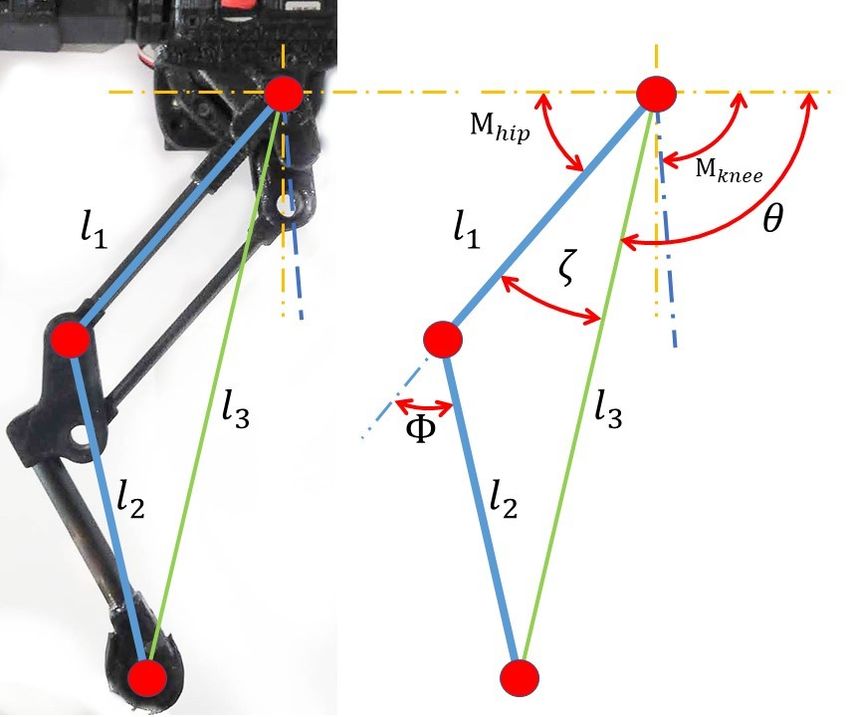
given system (in standing configuration similar to Figure 2)
                                                                  is situated 35 mm below the hip axis.

                                                                                   Parameter                  Value
                                                                                   total leg length         230 mm
                                                                                   leg segment length       120 mm
                                                                                   min./max. hip joint    -45◦ / 45◦
                                                                                   min./max. knee joint   -70◦ / 70◦
                                                                                   max hip speed             461◦ /s
                                                                                   max knee speed            461◦ /s
                                                                                   max hip torque         29 kg-cm
                                                                                   max knee torque        35 kg-cm
        Fig. 2: Physical robot dimensions of Stoch.                                motor power (servo)        16 W

                                                                           TABLE I: Hardware specifications of leg.
cheetah [13], Aibo [14], Rhex [15], some of which are open
sourced, but not easy to reproduce.
                                                                  B. Leg design
                III. M ECHANICAL D ESIGN                             Every leg has two degrees of freedom, one each for hip and
   Stoch is a quadrupedal robot designed and developed in-        knee. Detailed view of the leg assembly is shown in Figure 4.
house at the Indian Institute of Science (IISc), Bangalore,       The key specifications of leg and actuators are summarized
India. The design philosophy behind Stoch is based on             in Table I. The emphasis in the leg design was to keep the
modularity, lightweight construction, ease of manufacturing,      inertia of the moving segments minimal. To achieve this,
rapid repair and reproduction.                                    all the actuators and transmissions are mounted to the main
   The robot design can be understood as an assembly of a         body. The leg mechanism is designed as a co-axial five bar
central body module and four leg modules. Figure 1 shows          linkage[11]. This is beneficial to ensure fast swing motions
an exploded view showing all of the modules of Stoch. The         with minimum leg inertia.
leg modules can be used in several types of morphologies             To fabricate the mechanism, the linkages are formed with
as shown in Figure 3. The body consists of carbon fiber           carbon fiber hollow tubes connected by 3D printed poly
(CF) hollow tubes along its length as strong and lightweight      lactic acid (PLA) connectors. This arrangement enables us
structural members. The front and back CF plates along with       to modify the link lengths with minimal effort. To further
3D printed poly lactic acid (PLA) hubs form rigid central         reduce the swing leg inertia, we’ve used CF tubes as journal
frame structure. The body also houses all electronic parts,       bearings and shaft at pivot joints instead of regular metal ball
cable routing and battery power supply. A salient feature of      bearings. This drastically reduces the weight of the robot.
this design is that the leg modules slide and ‘sit’ on CF tubes
                                                                  C. Actuation and sensing arrangement in legs
placed along the body length. Thus, the geometrical distance
between front and hind legs can be modified by changing the          Figure 4 (i) and (ii) depicts the assembly arrangement
CF tube lengths or the assembly positions of the leg modules.     of servo actuators to the leg linkages and rotary encoders.
Similarly, the distance between the left and right legs, which    For the joint actuation we have used standard servo motors
is constrained by the CF plates, can easily be customized.        (Knee: Robokits 35 kg − cm High Torque Servo, Hip: Kondo
This feature enables user to rapidly play and experiment with     2350HV Servo.The knee actuators are directly coupled with
the basic geometry of legs and body module.                       the 3D printed links, which in turn move the coupler links
   In this section, we first discuss the overall geometry of      and eventually the knee joints of the legs. The joint angle
the mechanical structure, and then focus on its individual        sensor (rotary encoder) for knee is connected with the linkage
components, i.e., body and leg design. Finally, we describe       via a laser cut steel gear. Similarly, the hip actuator transfers
the actuator and sensor arrangement on the legs.                  mechanical power to the hip link via a simple gear train
                                                                  (ratio 1 : 1), whereas the hip encoder is directly coupled to
A. Geometry of Stoch                                              monitor the hip servo angle via a 3D printed part.
   The Stoch is designed equivalent to the size of a miniature
Pinscher dog. There are four identical legs and eight actua-              IV. E LECTRONIC S YSTEM A RCHITECTURE
tors mounted in the robot, which are distributed equally. Each       In this section, we describe the electronic system architec-
leg has a hip and a knee joint, and the actuators provide         ture in light of the objectives achieved in Stoch. The platform
flexion/extension in each joint. As shown in Figure 2, the        achieved three main objectives using this architecture. First,
Stoch is 0.4 m long in total, with 0.25 m between front and       tele-operation of the robot, which is implemented via SSH
hind legs. It has a maximal hip height of 0.24 m with legs at     over wireless communication (Figure 6). Second, the low-
maximum stretch, a standing height of 0.22 m, and an overall      level implementation of the walking controller, which passes
height of 0.35 m from ground to the top of electronics and        on the desired joint configurations as commands to the joint
cables. The robot has 0.24 m of lateral spacing between left      actuators. And third, integrating sensory feedback with the
and right leg planes axes, and a maximum width of 0.27 m.         walking controller. The last one is achieved by reading and
The robot weighs around 3.1 kg and 3.7 kg with the battery-       recording different sensors without experiencing significant
pack. The estimated static centre of mass (COM) of the            delay.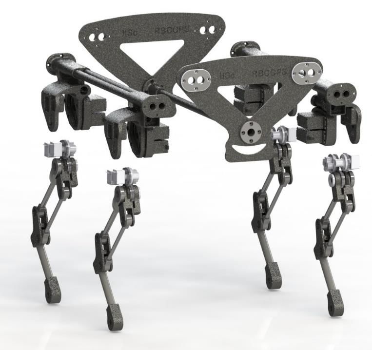
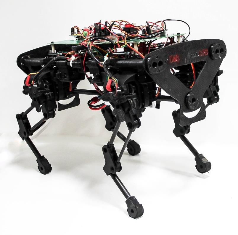
Fig. 3: Modular Configurations of Stoch: (a) X configuration, (b) O configuration, (c) XO configuration, (d) Natural quadruped
configuration.

Fig. 4: (a) shows the physical leg assembly, (b) shows the rendered counterpart of the leg assembly. (b) has three parts: (i)
sensor mounting and actuation hub, (ii) coupling and transmission of linkages with actuators and rotary encoders, and (iii)
exploded view of knee joint and CF journals.

   The encoders, servos and other parts selected for this work   result in generation of different behaviors and motions. In
are readily available, off-the-shelf components. This enabled    this robot, these parameter changes, are made during the
a quick adoption, rapid prototyping while minimizing the         process execution via SSH. We selected the keyboard as the
total cost.                                                      input device for remote operation.
               Equipment                   Details               B. Motor actuation
               Joint encoder      Bourns EMS22a
               IMU                     MPU-9150                     The actuators used in this robot are PWM enabled servo
               ADC                      ADS1115                  motors. To actuate these servos, we have used Adafruit
               PWM driver        Adafruit PCA968                 PWM drivers, connected with the central compute platform
               Servo              Kondo 2350HV
                               Robokits RKI-1203                 (Raspberry Pi3) over I2C Bus. In this robot, there are two
               Computer           Raspberry Pi 3b                sets of servos (see section III-C). These servos operate at
                                                                 11.1 V and 7.4 V respectively.
      TABLE II: Electronics hardware specifications.
                                                                 C. Sensory feedback
A. Tele-operation                                                   The sensory inputs contain signals from joint encoders,
   The walking controller operates by changing internal pa-      inertial measurement unit and limit switches. The angular
rameters of the Central Pattern Generator (CPG), such as the     position of each motor shaft is measured by externally
frequency, phase difference and amplitude. These changes         coupled absolute magnetic encoders. Each encoder is read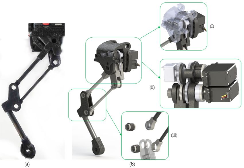
sequentially by the RPi3 via a multi-duplex, SPI Bus. The          αω , αR are used to determine the corner frequency of these
low-level drivers are used to pass the values to the primary       filters. ∆ is the discrete or event based input provided by
process in real-time using shared memory. We used the limit        the user or the sensors on-board. In this work, the filters are
switches for self-calibration and failure prevention at the        used in places where a discrete signal is added by the user
joints. These switches are connected to an analog to digital       or by some feedback in response to an event.
converter on the I2C Bus.                                              After the phase (φi ) is determined, any function described
   The center of mass of the robot, is estimated by the inertial   in form of φi can be used to create the endpoint behaviour
measurement unit (IMU). The states observed by the IMU             of the ith leg. We have
are three axis acceleration, three axis angular velocity etc.
Using sensor fusion, the IMU can also estimate the roll,                         Xd,i = Xd (φi ) = [x(φi ) y(φi )]             (5)
pitch, yaw of the robot. The IMU is placed close to the                                   n
                                                                                          X
geometric center of the chassis and is connected to the I2C                      x(φi ) =    Wx,j,i fx,j (φi )                 (6)
bus.                                                                                       j=1

                 V. WALKING C ONTROLLER                               In the above equations, x(φi ), y(φi ) represent the desired
                                                                   end point position values of the leg from the hip joint
   In this section, we describe the design of the control
                                                                   of the ith leg. This scheme can also be used to generate
architecture of Stoch. The controller is based on the use
                                                                   r(φi ), θ(φi ) in polar co-ordinates which are used in the
of nonlinear coupled oscillators, called as Central Pattern
                                                                   reinforcement learning framework [1]. The constant vectors,
Generator (CPG) [16], [4]. This approach uses a group
                                                                   Wx,i,j , are the weights associated with the basis functions,
of polynomials associated with the coupled oscillators to
                                                                   fx,j . Similarly we can generate y(φi ) with weights and basis
generate the desired patterns at the end point. We will first
                                                                   function. The patterns generated in Cartesian or in polar co-
describe the methods used to develop the rhythmic patterns
                                                                   ordinates are then transformed into joint co-ordinates via
using CPG, and then discuss inverse kinematics used to
                                                                   inverse kinematics.
transform these patterns into desired joint angles.

A. Central pattern generator                                       B. Inverse kinematics
   Central pattern generators (CPGs) are neural networks              Having obtained the coordinates (either in the form of
capable of producing coordinated patterns of rhythmic ac-          polar coordinates (r, θ) or Cartesian coordinates (x, y) of end
tivity without any rhythmic inputs from sensory feedback           points), we generate the joint angles via inverse kinematics.
or from higher control centers [5]. In this work, the neural       Figure 7 describes the leg configuration and the variables.
network has been replaced with nonlinear coupled differen-         If the end points of the robot are described in Cartesian
tial equations. When a signal is provided with oscillation         coordinates, then ??–?? are used to determine the joint angle.
frequency (ω), the CPG begins to produce rhythmic signals          In case the description is in polar co-ordinate, ?? can be
of a predetermined pattern. The oscillation frequency updates      avoided, since l3 and θ are directly provided. The inverse
the phases (φ) and the coupling ensures the phase offsets (Φ)      kinematics are given by
between the oscillators. This difference in phase offset results                     p                         y
in the generation of different types of gaits. The equations                    l3 = x2 + y 2 , θ = arctan                      (7)
for the CPG are given as                                                                      2                 x
                                                                                               l − l12 − l22

                                                                                Φ = arccos 3                                    (8)
        ω̇ = αω (ωd − ω)                                     (1)                                   2l1 l2

                       N                                                                          l2 sin Φ
                                                                                ζ = arctan                                      (9)
                       X
        φ̇i = ω +            Ki,j sin (φi − φj + Φi − Φj )   (2)                               l1 + l2 cos Φ
                       j=1
                                                                                qhip = θ + ζ, qknee = Φ + qhip ,              (10)
        φi = mod(φi , 2π)                                    (3)
        Ẋ =   φ̇X0d   + αX (Xd − X) + ∆                     (4)   where, l1 , l2 are the hip and knee lengths of the robot. Since
                                                                   each robot has a different reference frame associated with
    where, ω, ωd are the current and target oscillation fre-       legs, the joint angles are linearly transformed to obtain motor
quency of the legs, in radian per second. φi is the phase of       angles.The motor signals are then transformed to a pulse
the ith internal pattern generator. φ is the vector containing     width modulation (PWM) signal to drive the motors.
the φi . Φi is the phase difference between the ith leg and the
first leg. Ki,j are coupling constants. ?? and (4) represent                      VI. E XPERIMENTAL R ESULTS
low pass filter in time domain [5]. These filters ensure there
are no discontinuous changes in the variables. The low pass           In this section, we will describe various strategies under-
filter in ?? [16] is modified such that, periodic signal of any    taken to generate the different types of robot behaviors. First,
desired frequency can pass through but undesired signal of         we discuss the various types of flat ground walking gaits.
the high frequency can not. In ??, X, Xd are the current and       Next, we describe the abduction free turning, and then finally
the desired state values and X0d = ∂Xd /∂φ. The constants          describe the transitions between these gaits.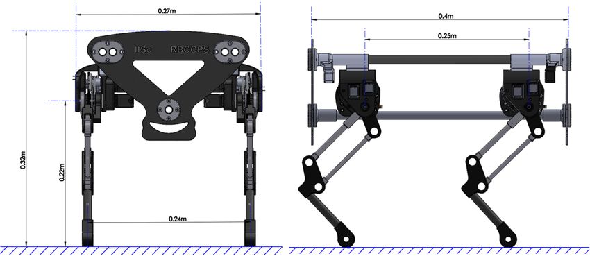
Fig. 5: Schematics of electronics and communication network.
weights, we can obtain the desired end point trajectories and
the velocities. We get
5
X 5
X
xi = fk,j (φi )Wx,i,j , yi = fk,j (φi )Wy,i,j , (11)
j=0 j=0
where, xi , yi are the target x, y coordinates of the ith leg.
fk,j (φi ) is the j th kinematic motion primitive [1], which
essentially is a polynomial of φi . The comparison of speeds
obtained for various gaits. A more detailed description of the
basis functions are given in [1].
2) Turning: The current model of Stoch, does not contain
Fig. 6: Controller and tele-operation schematic. any abduction. This limits us to realization of abduction
free/locked turning. We set the X axis (forward-backward)
movement of the desired leg to zero, and use
xturn,i = αt,i xi (12)
[1, 0, 0, 1]
left turn
αt = [0, 1, 1, 0] right turn (13)
[1, 1, 1, 1] no turn
where αt is the vector containing the turning coefficients
and xturn,i is the target x axis position of the ith leg. To
avoid discontinuous changes in the motion, we pass the αt
through a low pass filter, ??. This results in a smooth trot-
turn transition.
3) Gait transition: In this section, we will provide a gen-
eral methodology for transitioning between the flat-ground
walking gaits. In Section V-A, we described the phase offset,
Fig. 7: Inverse kinematics of robot leg. Φ, as a constant set of values which can be changed to obtain
various gaits. This change can be achieved, on the fly, by
1) Flat ground walking: On the flat plane, we have passing the desired phase offset through a low pass filter:
introduced 6 different types of gaits, trot, gallop, bound,
Φ̇i = αΦ (Φd,i − Φ) (14)
walk, modified trot 1 and modified trot 2. We have used
the basis function based approach [1] to store the information where Φd,i is the desired phase offset of the ith leg, and Φi
about the trajectories in a few constant values. These constant is the current phase offset of the ith leg. This allows for a
values are stored in the weight matrix (Wx , Wy ). Using the smooth change in the phase values.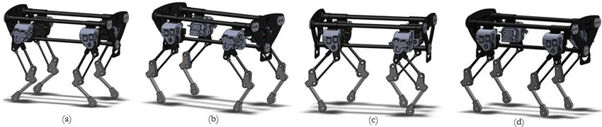
A. Video Result                                                                 [11] A. De and D. E. Koditschek, “Vertical hopper compositions for preflex-
                                                                                     ive and feedback-stabilized quadrupedal bounding, pacing, pronking,
   Video results of walking experiments on the Stoch                                 and trotting,” The International Journal of Robotics Research, vol. 37,
are available on https://youtu.be/Wxx9pwwTIL4.                                       no. 7, pp. 743–778, 2018.
                                                                                [12] H. Kimura and Y. Fukuoka, “Biologically inspired adaptive dynamic
Specifically, we show trot, bound, gallop, walk gaits on                             walking in outdoor environment using a self-contained quadruped
the robot. Additionally turning and gait transitions are also                        robot:’Tekken2’,” in Intelligent Robots and Systems, 2004.(IROS
shown. Further, the animation and physical assembly is also                          2004). Proceedings. 2004 IEEE/RSJ International Conference on,
                                                                                     vol. 1. IEEE, 2004, pp. 986–991.
shown in the video for easy understating of the Stoch design.                   [13] W. Bosworth, S. Kim, and N. Hogan, “The mit super mini cheetah:
                                                                                     A small, low-cost quadrupedal robot for dynamic locomotion,” in
                        VII. CONCLUSION                                              Safety, Security, and Rescue Robotics (SSRR), 2015 IEEE International
                                                                                     Symposium on. IEEE, 2015, pp. 1–8.
   This work presents a custom built quadruped robot along                      [14] “AIBO robot,” https://us.aibo.com/.
                                                                                [15] Rhex, “RHex robot,” https://www.bostondynamics.com/rhex/.
with its design, software, control framework and experimen-                     [16] M. Ajallooeian, J. van den Kieboom, A. Mukovskiy, M. A. Giese, and
tal validation on the hardware. Compared to other existing                           A. J. Ijspeert, “A general family of morphed nonlinear phase oscillators
quadruped robots, our platform requires less resource and                            with arbitrary limit cycle shape,” Physica D: Nonlinear Phenomena,
                                                                                     vol. 263, pp. 41–56, 2013.
costs under $1000. Several gaits were realized such as walk,
trot, gallop, and bound. Additionally, the robot can turn with
a small radius via CPG based gait transitions, without the use
of abduction. The robot reached a maximum forward speed
of 0.6 m/s. An open-loop controller was used to set the speed
and direction in all these experiments. Future work involves
increasing the payload, and also incorporate external sensors
for closed-loop control of the quadruped.

                     ACKNOWLEDGMENT
  We acknowledge Ashish Joglekar, Rokesh Laishram and
Balachandra Hegde for help in software development, Car-
bon fibre component manufacturing and PCB design.

                             R EFERENCES
 [1] A. Singla, S. Bhattacharya, D. Dholakiya, S. Bhatnagar, A. Ghosal,
     B. Amrutur, and S. Kolathaya, “Realizing learned quadruped locomo-
     tion behaviors through kinematic motion primitives,” arXiv preprint
     arXiv:1810.03842, 2018.
 [2] A. T. Sprowitz, A. Tuleu, A. J. Ijspeert et al., “Kinematic primitives
     for walking and trotting gaits of a quadruped robot with compliant
     legs,” Frontiers in computational neuroscience, vol. 8, p. 27, 2014.
 [3] A. Spröwitz, A. Tuleu, M. Vespignani, M. Ajallooeian, E. Badri, and
     A. J. Ijspeert, “Towards dynamic trot gait locomotion: Design, control,
     and experiments with cheetah-cub, a compliant quadruped robot,” The
     International Journal of Robotics Research, vol. 32, no. 8, pp. 932–
     950, 2013.
 [4] A. T. Sprowitz, A. Tuleu, M. Ajaoolleian, M. Vespignani, R. Moeckel,
     P. Eckert, M. D’Haene, J. Degrave, A. Nordmann, B. Schrauwen et al.,
     “Oncilla robot: a versatile open-source quadruped research robot with
     compliant pantograph legs,” Frontiers in Robotics and AI, vol. 5, p. 67,
     2018.
 [5] A. J. Ijspeert, “Central pattern generators for locomotion control in
     animals and robots: a review,” Neural networks, vol. 21, no. 4, pp.
     642–653, 2008.
 [6] H.-W. Park, S. Park, and S. Kim, “Variable-speed quadrupedal bound-
     ing using impulse planning: Untethered high-speed 3d running of
     mit cheetah 2,” in Robotics and automation (ICRA), 2015 IEEE
     international conference on. IEEE, 2015, pp. 5163–5170.
 [7] M. Hutter, C. Gehring, M. Bloesch, M. A. Hoepflinger, C. D. Remy,
     and R. Siegwart, “StarlETH: A compliant quadrupedal robot for fast,
     efficient, and versatile locomotion,” in Adaptive Mobile Robotics.
     World Scientific, 2012, pp. 483–490.
 [8] “SpotMini robot,” https://www.bostondynamics.com/spot-mini/.
 [9] M. Hutter, C. Gehring, D. Jud, A. Lauber, C. D. Bellicoso, V. Tsounis,
     J. Hwangbo, K. Bodie, P. Fankhauser, M. Bloesch et al., “Anymal-a
     highly mobile and dynamic quadrupedal robot,” in 2016 IEEE/RSJ
     International Conference on Intelligent Robots and Systems (IROS).
     IEEE, 2016, pp. 38–44.
[10] “Laikago robot,” http://www.unitree.cc/.
You can also read