4 Superconducting Transformers
←
→
Page content transcription
If your browser does not render page correctly, please read the page content below
4 Superconducting Transformers

Jan K. Sykulski

     Electrical Power Engineering, School of Electronics and Computer Science
     University of Southampton, Southampton SO17 1BJ, UK

Abstract The chapter provides an overview of power applications of High
Temperature Superconductivity (HTS) with emphasis on superconducting
transformers. Properties of available HTS materials are reviewed and model-
ling aspects briefly introduced. A conceptual design of a 240 MVA HTS grid
autotransformer is summarised and principal features discussed. The eco-
nomics of parallel operation is addressed. Finally, details of a small HTS
demonstrator built and tested at Southampton University are provided.

I.      INTRODUCTION

Recent catastrophic black-outs in New York, London and Italy (August and Sep-
tember 2003) have exposed major vulnerabilities in existing generation, transmis-
sion and distribution systems. Severe underinvestment, aging technology and con-
servatism in the approach to innovation are being blamed and have created a
situation where reliability of the entire system is under question. Resources need
to be directed into technologies that have the potential to improve the integrity of
the system; high temperature superconductivity has such potential. It also has a
positive environmental impact by significantly reducing the losses as well as size
and weight of the power devices.
   The advent of high-temperature superconducting (HTS) materials has renewed
interest in the possibilities for superconducting power apparatus offering real eco-
nomic benefit, within power ratings typical of present system practice. Previously
developed low-temperature superconductors (LTS) required cooling by liquid he-
lium to about 4.2 K, with advanced cryogenic technology that is expensive both in
terms of cost and of refrigeration power expended per unit of heat power removed
from the cryostat. The technology for the new materials, which may be based on
liquid nitrogen (LN2) at temperatures up to about 78 K, is simpler and cheaper,
and the ratio of refrigeration power used to heat removed is reduced from over
1000 to about 25. There is significant activity around the world regarding applica-
tions of HTS materials to cables, motors, generators, fault current limiters, energy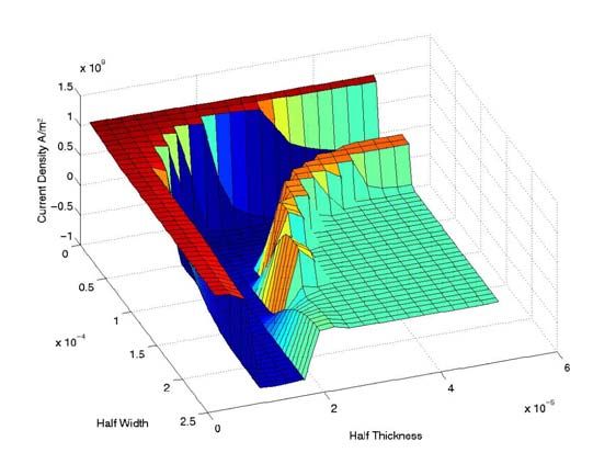
2

storage devices and transformers. This review builds on the material published
previously by the author [1−9] and reflects on the experiences with HTS technol-
ogy in electrical power applications at the University of Southampton, United
Kingdom. More information may also be found on a dedicated web page [10].

II. PROPERTIES OF HTS MATERIALS

The announcement in April 1986, by Muller and Bednorz (IBM) of superconduc-
tivity in the perovskite structure Lanthanum-Barium-Copper oxide at 30K, was an
important step towards a wider application of superconductivity [11]. This was
followed by the discovery of Wu and co-workers in January 1988, of
Y1Ba2Cu3O7−8 (YBCO or 123), with a transition temperature of 93K, bringing su-
perconductivity above the boiling point of liquid nitrogen (77.4K at 1Atm), a
cheap and widely available cryogen. There has since been much effort on the
search for new materials, and the optimization of processes for production of thin
films (
3

   Thallium compounds
         (TlPb)1Sr2Ca2Cu3O9                           (1223) Tc = 120 K
         Tl2Ba2Ca2Cu3O10                              (2223) Tc = 125 K
   Mercury compounds
         Hg1Ba2Ca2Cu3O10                              (1223) Tc = 153 K

III. MODELLING AND SIMULATION

HTS materials exhibit strong flux creep effects [12]. When modelling power loss
mechanism due to a flow of alternating current it is therefore not sufficient to use
a critical state model [13], which has proved successful when dealing with low
temperature superconductors, and it is necessary to consider the flux creep E–J
characteristic. A flux creep region is well described by the Anderson-Kim model

                                      E = K1 H sinh K 2 H J            (               )       ,              (1)

where K1 and K2 are parameters related to temperature and the properties of the
material [12], or a simpler relationship suggested by Rhyner [14] where

                      E = E c (J / J c ) α                     ,        ρ = ρ c ( J / J c ) α −1 .            (2)

   The critical current density Jc corresponds to an electric field Ec of 100μVm−1,
and ρc = Ec/Jc. The power law (2) contains the linear and critical state extremes
(α=1 and α→∞ respectively). It has been found that for practical HTS materials
α≈20 and thus the system is very non-linear.
   Using the Rhyner model the governing field equation takes the following form
in a two-dimensional space

                                           ∂⎧                                                   ⎫
                                                                                      1
                            ∂ 2E           ∂ 2E                                           −1
                                                                                                              (3)
                               +     = μ 0    ⎨σ c E                                  α
                                                                                               E⎬ ,
                            ∂x2 ∂ y2       ∂t ⎩                                                 ⎭

where E=Ez /Ec for brevity and σc=Jc /Ec [6]. Using a rectangular space mesh
Δx×Δy, a Finite Difference scheme may be built which yields

                            1                                      1
                                −1                                     −1
              E ij( k +1)   α        E ij( k +1) = E ij( k )       α        Eij( k ) + Δt ⋅ C ij = K ij   ,   (4)

                                                                        α −1
                                           Eij( k +1) = K ij                   K ij    .                      (5)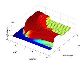
4

where

             {
        C = μ 0σ c (Δx )2   } {(E
                            −1       k
                                    i +1, j             )            (                    ) (    ) }
                                              + Eik−1, j + R 2 Eik, j +1 + Eik, j −1 − 2 R 2 + 1 Eik, j   (6)

and R=Δx/Δy. The indices i and j denote the nodal addresses in the (x,y) space.
  The loss over a cycle can then be calculated using numerical integration as

                                          T

                                          ∫ ∫ ( J ⋅ E ) dV dt
                                          0V
                                                                                  .                       (7)

   The stability requirements for the numerical solution are severe and in order to
make the process as fast as possible the time steps are adjusted at each step using
the criterion

                                                            1                 1
                                                                −1       1−
                                              σ c μ 0 E α Ec                  α
                                 Δt ≤                                                 .                   (8)
                                                   ⎛ 1   1                    ⎞
                                               2α ⎜⎜ 2 + 2                    ⎟
                                                                              ⎟
                                                   ⎝ Δx Δy                    ⎠

   It has been shown in [6] that field penetration in HTS tapes can be modelled
accurately as a highly non-linear diffusion process described above. Knowing AC
losses is of paramount importance in design of HTS power devices as these losses
are released at low temperature. Figures 2 to 4 show typical results of simulations.

Fig. 2. Current density distribution at the instant of a quarter of the maximum current
5 Fig. 3. Current density distribution at the instant of max current Fig. 4. Current density profiles through the tape thickness The effects of non-linearity have been found to be much stronger than experi- enced in linear conductors and thus for larger currents (deeper field penetration) the 2D analysis is essential, despite a large aspect ratio of the tape. The analogy with the linear case only works well for smaller currents where a simpler 1D model is quite acceptable.
6

IV. 240MVA GRID AUTOTRANSFORMER

A design feasibility study was conducted for a 240MVA high temperature super-
conducting grid auto-transformer [1]. The principal feature of the design is the
removal of the copper windings and their replacement by HTS equivalents. These
are only a fraction (less than 10%) of the bulk of the conventional windings. The
inevitable result is windings of reduced mechanical strength, which will stand nei-
ther the radial bursting forces nor the axial compressive forces that occur during
through-fault conditions without special strengthening structural features. The tap
winding is kept outside the cryostat to avoid the heat which could otherwise flow
into liquid nitrogen through a large number of connections. With the bulk of the
ohmic losses (in common and series windings) removed, it is possible to cope with
the core loss and remaining ohmic loss (in the tap windings) by forced gas cool-
ing, leading to an oil-less design of transformer. This has a great advantage of re-
ducing fire risk and environmental hazard from oil spillage. Furthermore, the need
for an explosion-proof outer steel tank is removed – though some form of enclo-
sure must be provided for weatherproofing and acoustic noise reduction.
    The superconducting windings have small thermal mass and are cryogenically
stable (i.e. capable of returning to normal operation after a period of abnormal
heating without disconnecting and cooling down) over only a small range of tem-
perature rise. In consequence, the HTS design has very little capability to recover
from a through fault without disconnection, in contrast to a conventional trans-
former. This is the chief weakness of the HTS design; however, the HTS design
can survive a through fault, though it subsequently needs disconnecting for a pe-
riod, and there is also good overload capability.
   The principal parameters of the suggested transformer design are listed below:
        kVA:                               240,000
        Normal Volts:                      400/132 kV
        Tappings:                          132 kV + 15% - 5% in 14 steps
        Line current at normal volts:      346/1054 A
        Diagram No:                        Yy0 Auto
        Guaranteed reactance:              20%
        Rated current densities:
              series winding* = 39.1 A/mm2
              common winding* = 36.9 A/mm2
              tap winding = 3.0 A/mm2 (conventional)
              (* average over composite conductor section, comprising both super-
              conducting and matrix materials).
   A short summary of the principal features is provided below (based on [1]).
   Core. Similar to a conventional design, but with leg length and window spans
reduced and consequent saving in core weight and overall size.
   Tap change arrangements. Copper tap windings retained, adjacent to core
leg, outside the cryostat, connected to a tap-changer, both of conventional design.
7 Cooling of core and tap winding. Forced-convection gas cooling, probably ni- trogen. Gas is forced through axial ducts to cool the core legs and tap windings. Top and bottom yokes fitted with fibreglass cowling to contain the fanned gas and direct it over yoke surfaces. Common and series windings. Constructed of rectangular section composite conductor comprising about 33% superconducting fibres and 67% matrix metal. The inter-turn insulating tape is applied to one face of the conductor. Individual tapes making up the conductor will be transposed in a normal way. Discs at the high-voltage ends of the series windings interleaved in pairs. Winding reinforcement. Outer diameter of series (high voltage) winding rein- forced with fibreglass hoops (possibly pre-stressed) or continuous cylinder. Sub- stantial inner cylinder with multiple spacing sticks supports inside diameter of common winding. Annular clamping plates top and bottom of complete in- cryostat winding assembly, pulled together by eight through-bolts or studs, all constructed of insulating material. Cryostats. One cryostat per leg, each cryostat comprising a vacuum vessel constructed of double-skinned fibreglass, with the vacuum continuously pumped. Cryostat pressure will be slightly in excess of 1 bar, containing nitrogen at 78 K. The intermediate-voltage leads pass through the top lid. High voltage lead passes centrally through cryostat wall. Fault and overload capability. For any substantial through fault, disconnec- tion is required and a period of minutes is needed before reconnecting. Trans- former can survive the most severe through fault for about 170 ms, within which time disconnection must be achieved. Internal faults sensed by in-built monitors or terminal voltage and current sensors, which initiate disconnection. Overload capa- bility of 100% is expected. Housing. Oil-less design obviates need for a tank, which is replaced by a steel structure carrying load exerted by bushings. External housing required for weath- erproofing, gas-seal for the forced-convection nitrogen coolant and acoustic noise reduction. Table I summarises the total losses of the HTS transformer design and com- pares them with the corresponding figures for a conventional ‘reference’ design. Losses are expressed in percentage form with the total loss in conventional design taken as 100%. Table II shows all the significant global features, covering size and construction as well as performance. Table III shows estimates of saving/expenditure components based on continu- ous operation in rated conditions. It is clear that an expenditure on extra equip- ment and materials is offset by the enormous value of the saved losses (taken over a 10-year period and discounted at 9.5% per year). However, because of the re- dundancy built into the system for security, the load factor of a grid transformer is remarkably low and may be taken as 0.23 average and 0.26 rms. For such load conditions a pessimistic estimate suggests that the total equivalent first-cost saving may now become a net increase of first-cost equivalent expenditure of about 20%.
8

Table I. Loss analysis (total loss of conventional design = 100%)

                                HTS             Conventional
Core loss                         8                  9
Clamp stray loss                  5                  5
Tank loss                         -                  7
Total copper loss              3)

Table III. Cost savings on continuous full-load

Savings/(expenditure)                                                                                %
Saving on core plate                                                                                  1
Saving on continuously transposed copper                                                              7
Saving on copper losses, discount over 10 years                                                      65
Cost of refrigeration plant                                                                          -21
First-cost equivalent expenditure on refrigerator drive power, discount over 10 years                -6
Cost of AC conductor, total of 7371 amp-kilometres                                                   -10
Total equivalent first-cost saving                                                                   36
(all values are referred to the overall first cost of the conventional transformer, which is taken as 100%)
9 On the other hand a common practice is to have two transformers fully rated normally connected in parallel. It is thus worth considering an arrangement of an HTS transformer normally connected, in parallel with a conventional transformer normally disconnected but capable of being switched on quickly when required (e.g. during through fault). Hence savings on the losses of the conventional trans- former will be very significant. This arrangement is discussed in the next section. V. PARALLEL OPERATION Figure 5 shows a typical arrangement of parallel connected transformers. Each transformer is usually rated to take the maximum load on its own, and because that maximum load rarely occurs, the load factor for a typical National Grid trans- former in the UK is low, around 23%. A typical probability density function for such a transformer is shown in Fig. 6. Fig. 5. Conventional arrangement of parallel transformers A suggested scenario is therefore to replace one of the conventional transform- ers (say SGT1 in Fig. 5) with a HTS “equivalent”. In normal operation the SGT2’s breaker is open and the load passes through SGT1 (HTS). In the event of a through fault, SGT2’s breaker is rapidly closed and SGT1’s opened. This may re- quire faster than usual breakers and associated protection but there is no reason to think that this may not be achieved within the 200ms required. Thus in this con- figuration it should hardly be necessary to ever use SGT2 (only during faults or
10

maintenance outages) and so it may be possible to de-rate this transformer. The
modified probability density distribution is shown in Fig. 7.

Fig. 6. Probability density of load for a typical grid transformer

Fig. 7. Load probability density and loss as a function of load for a HTS transformer in parallel
with a (normally) unconnected conventional unit. The mean load is around 0.7 p.u.

   Following the argument put forward in [5], assuming a capital cost of a
240MVA transformer of £1.0M, per unit loss to be 600kW and cost of losses over
the transformer life to be £3,000 / kW, we can assess the costs as follows:

Costs (£k)               Superconducting + conventional              2 × conventional
Transformer capital      1,000 + 1,230                               2,000
Losses                   0.105 × 600 × 3                             0.426 × 600 × 3
Total                    2,419                                       2,768
11

   This simplistic analysis shows that the combination of HTS and conventional
transformer is a lower cost option. Moreover, by inspecting Fig. 7, it is clearly
possible to optimise this further by reducing the nominal rating of the HTS trans-
former thus reducing capital cost. It can be seen that the load would “hardly ever”
go much above 1.5 p.u. so the HTS transformer could be of a smaller rating.

VI. HTS TRANSFORMER DEMONSTRATOR

A small single-phase 10kVA HTS demonstrator transformer was designed, built
and tested at Southampton University [8, 9]. In order to limit the material cost
(predominantly the cost of the superconducting tape), it was decided that the
nominal rating at 78K should be 10kVA and only one winding, the secondary,
should be superconducting; this also had the benefit of allowing direct comparison
of performance between conventional and superconducting windings. The secon-
dary current at this load is 40A. Since the large space required for thermal insula-
tion between copper and superconducting windings increases the radial flux densi-
ties and leakage reactance, a 3 limb construction was used with the two windings
on the centre limb. This arrangement minimises both of these problems, and also
simplifies the design and construction. It is essential to reduce the radial compo-
nent of leakage flux in the superconducting winding, as being perpendicular to the
face of the tape it is most detrimental to its performance. For example, to carry
the peak current of 9.5A per tape, the perpendicular component of peak leakage
flux density must be less than 15mT, compared with 110mT for the parallel (axial)
component. Field plots with and without the flux diverters are shown in Fig. 8.

Fig. 8. Field plots with and without flux diverters
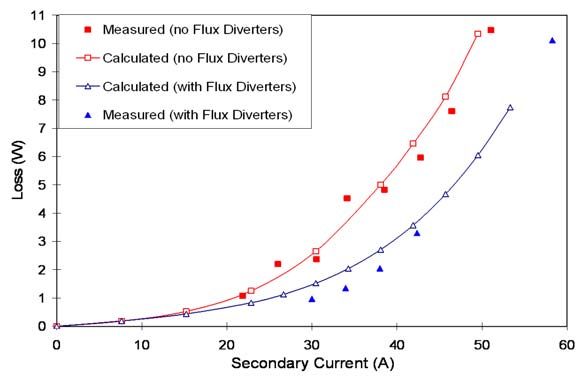
12

   Flux diverters are placed close to the ends of the super-conducting winding in
the cryostat and are constructed from low-loss materials to minimise the heat
which must be removed from the cryostat. The flux diverters are made from pow-
dered iron epoxy composite. A small test ring of this material produced a relative
permeability of 6, and the 50Hz iron loss at 78K with a peak density of 40mT is
less than 1500W/m3. This loss is about 25% higher than that at room temperature
due to the lower resistivity (the eddy-currents are resistance limited). A more ex-
pensive alternative, using flux diverters constructed of segments of ferrite with a
relative permeability in excess of 100, was considered. However finite element
analysis showed that, although the higher permeability did reduce the radial flux
density in the end coils, circulating currents would be more difficult to control.
The expected increase in the maximum capacity of the transformer is therefore
very small and cannot justify the use of ferrite rings.

Fig. 9. Measured andcalculated losses with and without flux diverters

   Flux diverters have proved to be a very effective means of controlling local
field distribution and reducing the winding losses. Figure 9 demonstrates such
losses as a function of secondary current. The graph also validates the numerical
procedures developed for estimating AC loss in HTS windings described in [7].
The most important observation resulting from these results is that the design re-
quirements differ quite significantly from conventional (that is non-
superconducting) transformers where the local shape of leakage field would not
have mattered, whereas for the HTS winding a two-fold reduction of loss has been
achieved. This emphasises the importance of very careful field modelling using fi-
nite element or similar software.
   The epoxy-filled fibre-glass cryostat (Fig. 11) consists of an inner annulus –
which contains the HTS winding and liquid nitrogen – fitting inside the outer an-
13

nulus. The cavity between the two halves is filled with superinsulation and evacu-
ated to form the thermal insulation around the inner cryostat. The whole assembly
is threaded by the centre limb of the transformer laminated core. The complicated
shape of the cryostat is necessary because it is not feasible to operate with a “cold”
core in view of the loss of nitrogen that would be caused by the iron losses. Nei-
ther can the cryostat be made of electrically conducting material because it would
act as a short-circuited turn.

Fig. 10. HTS winding of the 10kVA demonstrator

Fig. 11. The cryostat and current leads
14

VII. CONCLUSIONS

High Temperature Superconductivity has great potential in electric power applica-
tions (generators, motors, fault current limiters, transformers, flywheels, cables,
etc.) as losses and sizes of devices are significantly reduced. The technology is
now mature and prototypes are considered. The ability to predict and reduce all
‘cold’ losses is crucial to show economic advantages of HTS designs.

REFERENCES

[1] Sykulski J.K. et al – High Temperature Superconducting Power Transformers: Con-
     clusions from a Design Study – IEE Proceedings: Electrical Power Applications, vol.
     146, no 1, pp. 41-52, January 1999.
[2] Ship K.S., Goddard K.F. and Sykulski J.K. – Field optimisation in a synchronous gen-
     erator with high temperature superconducting field winding and magnetic core – IEE
     Proceedings (Science, Measurement and Technology), vol. 149, no 5, pp. 194-198,
     2002.
[3] Ship K. S. and Sykulski J.K. – Field modelling and optimisation of a high temperature
     superconducting synchronous generator with a coreless rotor – Fifth IEE International
     Conference on Computation in Electromagnetics, pp. 109-110, 2004. ISSN 0537-9989
[4] Sykulski J.K. – Applications of High Temperature Superconductivity in Electrical
     Power Devices: the Southampton perspective – Proceedings of Superconductivity UK,
     IEE Savoy Place, London, 2003.
[5] Sykulski J.K et al – The design, construction and operation of high temperature super-
     conducting transformers: practical considerations – Proceedings of 38th Session of
     the Int Conference on Large High Voltage Electric Systems (CIGRE), Paris, no 12-
     203, 27 Aug - 1 Sept 2000.
[6] Sykulski J.K. et al – 2D modelling of field diffusion and AC losses in high temperature
     superconducting tapes – IEEE Transactions on Magnetic, vol. 36, no 4, pp. 1178-82,
     2000.
[7] Sykulski J.K., Goddard K.F. and Stoll R.L. – A method of estimating the total AC loss
     in a high-temperature superconducting transformer winding – IEEE Transactions on
     Magnetic, vol. 36, no 4, pp. 1183-7, 2000.
[8] Sykulski J.K. et al – Design of a HTS demonstrator transformer – Institute of Physics
     Publ., pp. 571-4, 1999.
[9] Sykulski J.K. et al – High temperature superconducting demonstrator transformer: de-
     sign considerations and first test results – IEEE Transactions on Magnetics, vol. 35, no
     5, pp. 3559-61, 1999.
[10] http://www.superconductors.org/
[11] Muller K.A. and Bednorz J.G. – Possible high Tc superconductivity in the Ba-La-Cu-O
     system – J. Phys., B, vol. 64, pp. 405-407, 1986.
[12] Anderson P.W. – Theory of flux creep in hard super-conductors – Phys. Rev. Lett.,
     vol. 9, pp. 309-311, 1962.
[13] Bean C.P. – Magnetization of high-field superconductors – Rev. Mod. Phys., vol. 36,
     pp. 31-39, 1964.
[14] Rhyner J. – Magnetic properties and ac losses of superconductors with power law cur-
     rent-voltage characteristics – Physica C, vol. 212, pp. 292-300, 1993.
You can also read