5-axis CNC ultrasonic cutting machine: design and preliminary test
←
→
Page content transcription
If your browser does not render page correctly, please read the page content below
LIGO-T020198-00-R

                            5-axis CNC ultrasonic cutting machine:
                                          design and preliminary test

                  1
                   A.Bertolini, 1N. Beverini, 2G. Dal Lago, 3R. DeSalvo, 4F. Fidecaro
                             1
                             F. Francesconi, 1M. Francesconi, 2G. Omiccioli

                                 1
                                     Dipartimento di Fisica, Università di Pisa and INFM
                                            Via Buonarroti,2 5 6100 Pisa (Italy)
                                                     2
                                                      FAIMOND S.r.l.
                                          Via Fermi,25/27 36057 Arcugnano (Italy)
                                      3
                                 California Institute of Technology, LIGO Project
                          1200 E. California Blvd. MS-18-34, 91125 Pasadena, CA, USA
                                 4
                                     Dipartimento di Fisica, Università di Pisa and INFN
                                            Via Buonarroti,2 56100 Pisa (Italy)

1. Principles of the ultrasonic cutting

The use of ultrasonics for machining processes of hard and brittle materials is known since early 1950s
. The technology that has evolved since then, variously termed ultrasonic machining, impact grinding
or slurry drilling, relies on the cutting action of an abrasive slurry flowing between the vibrating tip of a
transducer and a work piece. All brittle materials – glass, technical ceramics, ferrite, quartz, tungsten
carbide, sapphire, ruby and even diamond – can be abraded in this way. The main feature of the
process is that the shape of the cavity produced by the tool very precisely emulates the contour of the
emitter tip. Other relevant peculiarities of the ultrasonic cutting are the absence of heating and the
extremely low stress levels (less than 2 MPa) applied to the work piece, making this process unique for
high precision machining of crystals for applications in optics and in semiconductor technology.

                                                             1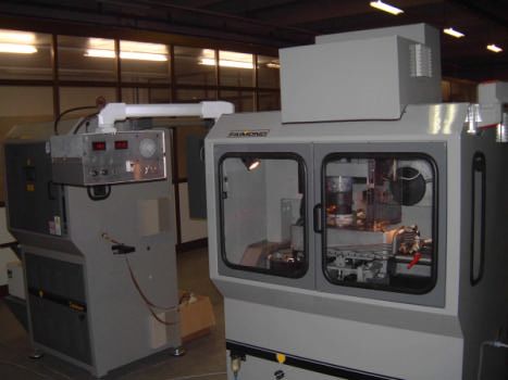
LIGO-T020198-00-R

The abrasive suspension is fed into the space between the work piece and the longitudinally vibrating
tool (see Fig.1). As the metal tool tip is brought in the vicinity of the machined surface eventually one
of the abrasive grains is squeezed between them. This grain becomes embedded in both surfaces as the
tool moves closer. The embedding of the abrasive particle in the tool material merely produces plastic
deformation. The embedding of the abrasive particle into the surface of a machined brittle material
causes a pocket to be chipped out. The surface of such a material disintegrates at once, whereas a metal
surface requires several cycles to disintegrate.
The minute particles of abraded material are removed along the surface perpendicular to the direction
of the tool vibrations. As the material is removed, a cavity is formed in the piece, exactly copying the
profile of the tool face. During the machining operation the abrasive particles participating in the
operation gradually erode, hence a liquid is fed into the machining zone, where it supplies fresh
abrasive grains and ensures the removal of the spent grains and material particles. Thus, the ultrasonic
machine tool must provide for vibrations of the tool at large amplitude (20 µmpp) and a given frequency
(around 20 kHz), and it must supply the required static force (a few kilograms per cm squared) to hold
the tool against the work piece and a continuous flow of abrasive suspension into the machining zone.
A diagram of an ultrasonic machine tool is shown in Fig.2.

Fig.2 Ultrasonic machine tool schematic

A ceramic stack piezoelectric transducer is the source of mechanical oscillations. It transforms the
electrical power received from the power supply (0.5-1.5 kW) into mechanical vibration power with a
typical 60-70 % of efficiency. However, the amplitude of the resulting ultrasonic vibration is

                                                   2
LIGO-T020198-00-R
inadequate for realization of the cutting process and a waveguide focusing device (“exponential horn”)
is fitted onto the end of the transducer, where it is designed to enhance the vibration amplitude at its
output end, with, of course, a corresponding decrease in area. The tool attached to the end of the
concentrator makes it possible to form a hole having a desired shape in the work piece. In order to
increase the vibration amplitude the vibratory system is designed to be driven at resonance, i.e., its
length is equal to an integral number of half-wavelengths at a given frequency. The vibratory system
formed by the transducer, concentrator and tool is rigidly clamped to the machine body at a nodal (zero
amplitude) point. This solution prevents losses of vibrational energy through dissipation into the body
of the machine. A load control mechanism stabilizes the static force between the tool and the work
piece, while the abrasive is continuously fed into the cutting zone by a suitable pumping system.
The efficiency of the ultrasonic machining depends first of all on the brittleness of the material. In the
machining of a pair consisting of a ductile material and a brittle one, the brittle material will break
down more rapidly, regardless of which material is executing vibrations. Thus, besides machinability
reasons, in order to limit tool wear the ultrasonic tool is generally made of soft steel or nickel, possibly
diamond-impregnated.
Material Relative machining speed ( % )
glass 100
silicon 50
fused silica 50
agate 40
sapphire 9
Table I. Relative machining speed of differente glasses and crystals. The machinability depends on the microhardness of the
material.
In Table I are reported relative machinability of glass and crystals having different machining speed.
Besides the performance, ultrasonic machining is characterized by the purity of the surface and
machining precision; these latter are determined mainly by the hardness of the machined material and
the grit size of the abrasive suspension. The precision is interpreted as the stability of the clearance
between the contours of the hole and the tool. Experience has shown that the lateral clearance is about
1.5 times the mean abrasive grain diameter.
3LIGO-T020198-00-R
Fig.3 SEM micrograph of a single crystal sapphire surface machined in our laboratory with boron carbide 220 mesh.
Irregularities of 1-5 µm can be observed.
The ultimate fluctuations of this clearance create a certain tolerance, which controls the machining
accuracy. This means that a machining accuracy of a few microns is achievable with 220-mesh
abrasive (see Fig.3 example); a better finishing can be obtained with a higher mesh. The surface purity,
which is determined by the mean micro-roughness height, also improves with increasing hardness of
the material inversely as the abrasive grain diameter. The performance of ultrasonic machining of a
given material depends on the vibration amplitude, frequency, and static force.
The machining speed v, defined as the volume of material chipped away in unit time, empirically
depends on above parameters as v ~ ξ ( Fst f )1/2. Where ξ is the tool vibration amplitude, Fst is the static
load and f is the frequency of operation. In experiments it has been found that the abrasion rate is often
proportional to the frequency, while non-linear frequency dependence of the machining speed comes
from changes in the abrasive concentration and in removal rate from the working clearance. The
machining speed is also determined by the hardness and grit size of the abrasive, which has to be
considerably harder than the work piece or at least of equal hardness. Most used ones are silicon
carbide and boron carbide. High-speed motion picture camera observations show that the disintegration
of the work piece material is caused by the impact of the tool directly against the abrasive particles
immediately close to the machined surface. The machining speed is diminished by the use of more
viscous fluids; this happens because the higher the streaming velocity the more rapidly the spent
comminuted abrasive can be replaced by fresh abrasive and, consequently, the greater will be the
4LIGO-T020198-00-R
machining speed. Cavitation also affects the machining process. On the one hand, the action of
cavitation bubbles on the abrasive particles tends to produce a uniform distribution of bubbles under
the tool, while, on the other hand, cavitation reduces the machining speed by the ejection of abrasive
particle, so that the abrasive concentration in the working gap is decreased.
The nature of the stresses at the boundary between the tool tip and abrasive suspension depends on the
elastic properties of the load (abrasive suspension and machined surface), the power delivered to the
transducer and the static force. The vibrations have a harmonic steady-state character while the stress is
impulsive. The mean force per period is equal to the static force. A fairly accurate mathematical model
of the single impact dynamics shows, in good agreement with the experiments, that the peak force (in
Kg) developed by the tool is given by F max ~ 1.7 Fst ξ1/2, with ξ in microns. Typically, from
experimental values of machining speed, the corresponding stress does not overcome 20 Kg/cm2, well
below the yield strength of every material of interest.
Fig.4 SEM micrograph of a 400 µm thick flex-joint machined from a 3-mm thick sapphire single crystal wafer.
2. Multi-axis CNC ultrasonic cutting
The “classic”, moulding-like, ultrasonic cutting process, with single vertical axis feed and shaped tools,
had a large diffusion and was development in Soviet Union during the sixties. In the West the cutting
has been gradually replaced with a mixed technology, named “twist drilling”, where the ultrasonic tool
is mounted on a high speed rotating spindle; in this case the diamond tool is in contact with the
5LIGO-T020198-00-R
workpiece and no abrasive slurry is used. In twist drilling the material removal rate is much higher
than in classic cutting but the process is not suitable for precision machining of crystals for optics or in
semiconductor processing where the minimal stress release is mandatory. For these reasons in the last
ten years the slurry cutting is having a new diffusion for high-tech applications. At present only two
american companies, Sonex and Sonic-Mill, produce “classic” process ultrasonic cutting machines,
with single axis feed, both manual and automatic. Recently the italian company FAIMOND introduced
into the market machines of comparable technological level for the jewellery industry. In 2001
FAIMOND R&D division, with the technical support of INFM-Pisa (Italy) and LIGO-Caltech, started
to design a new kind of ultrasonic cutting machine.
The machine has CNC feed along X, Y, Z and THETA (rotation) axes; a secondary vertical computer
controlled movement, in feedback with a high resolution load cell, stabilizes the tool pressure on the
workpiece. Instead of a mould-like tool, the new machine uses properly shaped chisels for lateral feed.
With respect to classic vertical slurry cutting, the chisel machining is much more versatile, it allows to
obtain more complex shapes and allows an easier load control, being the tool working surface constant.
The numerical control also allows a “hovering” machining, eventually with a finer grit, for surface
finishing purposes. All the features of classic slurry machining, that is absence of heating and low
stress, are preserved.
At present the only similar machine in the world was built twenty years ago by ONERA (Office
National d’Etudes et de Recherches Aerospatiales) in France and used for the construction of GRADIO
and STEP electrostatic levitation accelerometers. The same machine will be used for LISA inertial
sensors. All the potential scientific and technical applications of this unconventional machining
process are still almost unexplored. For instance, in interferometric gravitational wave detectors,
ultrasonic machining could be used for new mirror suspension mechanics realized in high quality factor
materials like fused silica, silicon or sapphire.
The prototype of the new machine has been recently tested at FAIMOND company; the preliminary
specs and features of the device are presented in the next section.
6LIGO-T020198-00-R
3. The prototype
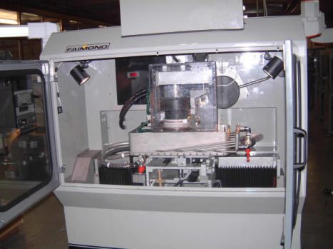
Fig.5 Front view of the 5-axis ultrasonic cutting machine prototype. On the left side is visible the ultrasonic generator, with
power and frequency controls. On the right, not visible in the picture, are mounted the PC for the axis control and the 9
inches CRT camera.
The frame of the machine is the same of a conventional 3-axis CNC mill; the table travel is 600 mm
along X and 120 mm along Y; the Z-axis slide travel is 150 mm. The slide ways are precision ground
and chromium coated; the movement is obtained with precision-ground ball screws and AC servo
brushless motors digitally controlled. Micrometer accuracy is achieved with high resolution (0.003
mm) optical position sensors. The ultrasonic head is mounted on a second upper Z-slide powered by a
fourth digitally controlled brushless motor; the rotation of the head (up to 1000 rpm around precision
ball bearings) is provided by a fifth motor, digitally controlled too.
Th whole head can also operate tilted, in principle up to 180°, for high speed chisel cutting.
The pressure of the tool on the workpiece is monitored by a precision load cell placed under the
machining plate; an adjustable counterweight system allows to compensate for the weight of the plate
and of the tuning mechanics. The signal from the load cell is processed by the computer and sent to the
ultrasonic head motor for the active load stabilization. The static machining load can be set from 0.2 to
10 Kg with a resolution of 0.01 Kg, as well as the feedback integration time. If necessary, a tool wear
compensation routine can be implemented in the control.
7LIGO-T020198-00-R
A suitable recirculating pumping system provides a continuous abrasive slurry renewal, in order to
keep a high cutting speed during machining; two selectable separate tanks with 8 liters of capacity store
different mesh grade boron carbide, grit 220 and grit 360 respectively for coarse and fine cutting. In
each tank a mixer maintains a constant concentration of the slurry.
Fig.6 Internal view of the machine. A polycarbonate transparent box (for high voltage safety) hosts the rotating ultrasonic
head with the centering slides and the piezoelectric transducer cooling system. The working table is surrounded by the anti-
splash container and by the secondary high-flow slurry feeding. Below the table (the protection carter has been removed) is
visible the load control system.
The ultrasonic power supply generates up to 800 W with sinusoidal waveform; a stack of four ring
piezoelectric transducer converts the electrical power into mechanical vibrations. The piezos are kept
at constant temperature by a refrigerated oil (Mobilect-45) flow in a sealed circuit; the cooling system
allows stable long time operation and prevents overheating of the transducers. The ultrasonic power is
transmitted to the workpiece by means of a 3/4 wavelength horn made of titanium alloy Ti6Al4V; the
horn, with an end diameter of 19 mm, is provided with a M6 threaded hole for tool fixing. The
ultrasonic head is designed for 20 kHz operation; a suitable feedback system acts on the generated
frequency to track changes of the electromechanical impedance of the piezo-horn-tool-slurry-
workpiece system; in this way the power transmitted to the tool is dynamically controlled for the
maximum available cutting speed.
All the signals for the CNC operation are managed by a PC embedded on the machine; a 32-bit logic
programmable controller is used to execute machining routines in standard EIA-ISO language.
8LIGO-T020198-00-R
A Windows-based interface has been implemented on the PC for the static load and the feed control
and monitoring. Preliminary test cycles of the machine have been done to check all the implemented
functions; the highlights of the test session are briefly presented below:
• The abrasive slurry pumping-mixing system is able to provide a continuous abrasive renewal
without any problem of re-precipitation of the boron-carbide. Care has to be taken only for long
time (week) inactivity. The secondary (high-flow) abrasive feed is able to wet all the working table
for large size workpiece machining; anyway when the high-flow irrigation is activated we have
verified the formation of heaps of boron carbide next to the corners of the container; a set of
compressed air nozzles will be implemented. For small size a suitable tooling is preferable to
contain the slurry just around the workpiece.
• The ultrasonic power supply and the automatic frequency tracking electronics are operating within
the specs. The high voltage sliding contacts of the rotating head showed some fault for speed over
200 rpm; different materials and design has to be used for operation up to 1000 rpm.
• The piezo cooling system is correctly operating keeping stably the transducers and the head
temperature at 20 °C.
• The CNC sensors and actuators work correctly; the power of all of the brushless motors is properly
dimensioned. Basic ISO cycles have been used for the tests.
• The static load dynamic control works properly. A special numerical ISO routine has been written
for this function: every 10 msec the program compares the signal from the load cell with the set
static value and changes the height of the ultrasonic head to restore the tool pressure; the increment
has been set to 0.01 mm. The load (2-2.5 Kg) is stable within +- 10 grams.
• The chisel machining has been tested on a sapphire disk (Mohs hardness 9). The following routine
has been implemented by the CNC:
- the tool moves along Z at constant static load by 0.03 mm;
- it moves along X and Y axes at constant height with a speed of 2mm/min;
- after the first cycle the tool comes back to the initial position and restarts.
Different tools have been tested: the cycle has been properly executed by using tool sizes ranging
from 4 to 300 mmq. Then the cutting speed for this mode of operation is at least 1mm3/min. Five
time faster cut has been obtained replacing the soft steel chisel with a diamond one.
9LIGO-T020198-00-R
• A classic mould-like machining run has been done on the same sapphire piece. In this case only the
constant load feed has been used. A 5 mm in diameter, 2 mm deep, hole has been machined in the
sapphire in 1.5 min, for a corrisponding cutting speed, surprisingly high, of 25mm3/min.
10LIGO-T020198-00-R
Prototype preliminary specs
- CNC ultrasonic cutting machine, 5-axes controlled X, Y, Z, THETA, LOAD; 0.003 mm
resolution optical position sensors.
- Cutting speed: 5 mm3/min in “chisel” mode, 25 mm3/min in “mould” mode, on a 9 Mohs
hardness material, with 220 mesh boron carbide slurry.
Technical details:
- size: 1280x1550x1950 mm
- weight: 800 Kg
- table size and travel: X=600mm, Y=120mm, Z=150mm
- secondary vertical way: LOAD=150mm
- head rotation THETA up to 1000 rpm
- head tiltable up to 180°
- ground slide ways, chromium coated and precision ground ball screws
- AC servo brushless motors digitally controlled for X, Y, Z, THETA, LOAD axes
- PC embedded with 32-bit logic programmable controller EIA-ISO standard
- Double irrigation and mixing system for grit 220 and grit 360; tank capacity 8 liters.
- Ultrasonic horn in titanium alloy Ti6Al4V
- Power ultrasonic generator 800 W, sinusoidal waveform; automatic frequency tracking in the
range 18-22 kHz.
- Piezoelectric stack converter oil cooled.
- Automatic tool pressure control with high resolution load cell selectable from 0.2 to 5 Kg with
0.01 Kg of resolution.
11You can also read