7100 RF Terminal - Owner's Manual - Worth Data
←
→
Page content transcription
If your browser does not render page correctly, please read the page content below
™

      7100 RF Terminal
                     Portable Radio Frequency Terminal

   Worth Data®
   7100 Series
 Host Controlled
RF Terminal System

www.worthdata.com                                        Owner’s Manual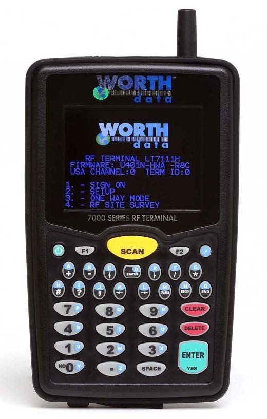
This equipment has been tested and found to comply with the limits for a Class A digital device, pursuant to Part 15 of the FCC Rules. These limits
are designed to provide reasonable protection against harmful interference in a residential installation. This equipment generates uses and can radi-
ate radio frequency energy and, if not installed and used in accordance with the instructions, may cause harmful interference to radio communica-
tions. However, there is no guarantee that interference will not occur in a particular installation. If this equipment does cause harmful interference to
radio or television reception, which can be determined by turning the equipment off and on, the user is encouraged to try to correct the interference
by one or more of the following measures:

      •      Reorient or relocate the receiving antenna.
      •      Increase the separation between the equipment and receiver.
      •      Connect the equipment into an outlet on a circuit different from that to which the receiver is connected.
      •      Consult the dealer or an experienced radio/TV technician for help.

Shielded cables must be used with this equipment to comply with the relevant FCC regulations. Changes or modifications not expressly approved in
writing by Worth Data may void the user's authority to operate this equipment.

This device complies with Part 15 of the FCC Rules. Operation is subject to the following two conditions: (1) this device may not cause harmful inter-
ference, and 2) this device must accept any interference received, including interference that may cause undesired operation.

This device complies with RSS-210 of Industry Canada. Operation is subject to the following two conditions: 1) this device may not cause interfer-
ence, and 2) this device must accept any interference, including interference that may cause undesired operation of the device.

The 7100 RF Terminals and B50X1 Base Station have been approved for use in the United States and Canada as a low power frequency hopping
spread-spectrum radio operating in the unlicensed 915 MHz frequency range.

                                                                                    The 7100 RF Terminal models have a laser scanner integrated with the Terminal as
                                                                                    one unit. The laser used is a Class II Laser Product and has a 1.2 Milliwatt Output.
                                                                                    To operate the laser scanner, aim the top of the case at a bar code, and press the
                                                                                    yellow scan key on the keyboard of the RF Terminal (and/or the Trigger on units
                                                 with a Handle- LT71XXH Models). The light source will turn off, once a successful scan has occurred or 2.5 seconds
                                                 has elapsed, whichever is first. Do not look directly into the laser light source with the "Scan Key" depressed; avoid
                                                 direct eye contact with the laser light source.

                                                 Warning labels to CAUTION LASER LIGHT – DO NOT STARE INTO BEAM are located as shown on the left:

                                                 There are no user adjustments or maintenance operations to be performed on the integrated laser scanner. Open-
                                                 ing the Unit Will Void the Warranty.

                                                 Caution - use of controls or adjustments or performance of procedures other than those specified herein
                                                 may result in hazardous laser light exposure.

    WARNING: Cables, Cable Assemblies, and Printed Circuit Boards can expose you to chemicals including lead and lead compounds which are known to the State of California to cause cancer and birth defects
or other reproductive harm. For more information, go to www.P65Warnings.ca.gov

   WARNING: Lithium-ion Batteries and/or products that contain Lithium-ion Batteries can expose you to chemicals including cobalt lithium nickel oxide, and nickel, which are known to the State of California to
cause cancer and birth defects or other reproductive harm. For more information, go to www.P65Warnings.ca.gov

    WARNING: Electrical cords, cables, product cords, wire assemblies, and carrying cases made with PVC can expose you to chemicals including DEHP, which are known to the State of California to cause cancer
and birth defects or other reproductive harm. For more information, go to www.P65Warnings.ca.gov

   WARNING: Plastic cases and product plastic housings made from polycarbonate or other plastics can expose you to chemicals including bisphenol A (BPA), which are known to the State of California to cause
cancer and birth defects or other reproductive harm. For more information, go to www.P65Warnings.ca.gov

                                        Worth Data, Inc.
                                        623 Swift St., Suite B
                                        Santa Cruz, CA 95060

© Copyright 2021 – Worth Data, Inc. - All Rights Reserved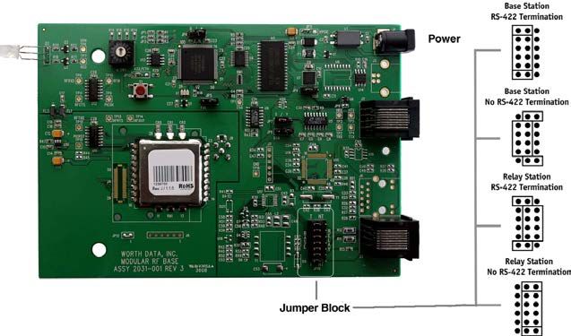
Table of Contents
Introduction................................................................................................................................................................................................ 1
    Differences ............................................................................................................................................................................................ 1
Quick Start Guide ...................................................................................................................................................................................... 2
    Step 1: System Overview ...................................................................................................................................................................... 2
    Step 2: Hardware Overview .................................................................................................................................................................. 2
    Step 3: Connecting the RF Base to the Host Computer ........................................................................................................................ 3
    Step 4: Installing Hardware Utilities ..................................................................................................................................................... 3
    Step 5: Running Hardware Utilities ...................................................................................................................................................... 6
Chapter 1: Installation ............................................................................................................................................................................... 9
    Components .......................................................................................................................................................................................... 9
    Installation Sequence ............................................................................................................................................................................ 9
    Connecting the Base Station ................................................................................................................................................................. 9
    Installation ........................................................................................................................................................................................... 11
    RF Terminal Operation ....................................................................................................................................................................... 12
    Recharging the RF Terminal Battery .................................................................................................................................................. 13
    Installing the Integrated Hardware Utilities Software ......................................................................................................................... 15
Chapter 2: RF Terminal Setup ................................................................................................................................................................. 16
    Using the Setup Menu on the RF Terminal ......................................................................................................................................... 18
    Bar Code Options ................................................................................................................................................................................ 21
    Bluetooth Settings: .............................................................................................................................................................................. 25
    Date & Time Setting ........................................................................................................................................................................... 25
    Speaker Settings .................................................................................................................................................................................. 26
    Laser Options ...................................................................................................................................................................................... 26
    LCD Options ....................................................................................................................................................................................... 27
    Other Settings ...................................................................................................................................................................................... 28
    System Tools ....................................................................................................................................................................................... 30
Chapter 3: Base Station Setup .................................................................................................................................................................. 31
    Base (B5011) and Relay Setup............................................................................................................................................................ 31
    Adding B5011 Relays ......................................................................................................................................................................... 34
    Base Station Cable Options ................................................................................................................................................................. 39
    B5021V Connection – Direct Ethernet ............................................................................................................................................... 40
    B5021R Connection - Ethernet Relay ................................................................................................................................................. 40
    Ethernet Base (B5021) Setup .............................................................................................................................................................. 41
Chapter 4: Operational Theory ................................................................................................................................................................ 50
    How the Two-Way RF System works................................................................................................................................................. 50
    How the One-Way RF System works ................................................................................................................................................. 51
    How Site Survey works....................................................................................................................................................................... 52
Chapter 5: Performance Issues................................................................................................................................................................. 53
    Evaluating your area of planned operation.......................................................................................................................................... 53
    Relay Stations ..................................................................................................................................................................................... 54
Chapter 6: Programming ......................................................................................................................................................................... 57
Before you begin programming… ...................................................................................................................................................... 57
    Failure Planning .................................................................................................................................................................................. 58
    Programming for the RF Terminal ...................................................................................................................................................... 59
    Base Station Error Feedback ............................................................................................................................................................... 66
    Control Keys for Possible Programming............................................................................................................................................. 69
    ASCII Control Character and Extended ASCII Conversion (2D scanner only).................................................................................. 69
Chapter 7: Programming Tools ................................................................................................................................................................ 70
    Concepts - ActiveX Object Programming........................................................................................................................................... 70
Chapter 8: Portable Printers ..................................................................................................................................................................... 73
Chapter 9: Voice Message Operations ..................................................................................................................................................... 75
    Why Use Voice Messages and Prompts? ............................................................................................................................................ 75
    Voice Prompts and the Integrated Hardware Utilities program .......................................................................................................... 75
    Tips for Using Voice Prompts............................................................................................................................................................. 75
Chapter 10: Troubleshooting ................................................................................................................................................................... 77
    General Considerations ....................................................................................................................................................................... 77
    Problems with a new installation: ....................................................................................................................................................... 78
    Terminal Error Messages .................................................................................................................................................................... 78
    Troubleshooting specific problems ..................................................................................................................................................... 79
    RF Terminal Problems ........................................................................................................................................................................ 81
    Problems reading Bar Codes ............................................................................................................................................................... 81
    No Scan Beam ..................................................................................................................................................................................... 82
    Problems with Voice Prompts ............................................................................................................................................................. 82
    If you still have a problem…............................................................................................................................................................... 82
Chapter 11: Firmware Upgrades ............................................................................................................................................................. 83
    RF Terminal Firmware Upgrades ....................................................................................................................................................... 83
    Base Station Firmware upgrades ......................................................................................................................................................... 83
Appendix A: How to scan a bar code ...................................................................................................................................................... 84
    1D Laser Scanners............................................................................................................................................................................... 84
    2D Optical Imaging Scanners ............................................................................................................................................................. 86
    ASCII Code Equivalent Table............................................................................................................................................................. 87
Introduction
The 7100 & 7200 RF Terminals are low cost, easy-to-use radio frequency mobile handheld bar code scanning RF Terminals
that communicates with PCs (or any computer) by RS-232 serial port, USB or Ethernet. These RF Terminals offers unprec-
edented power and ease of use, while maintaining compatibility with programs written for the older Worth Data Terminals.
The list of fantastic features includes:

    •   Low Cost
    •   Up to 3.3 mile range, LOS (10 x the competition)
    •   64 Terminals per Base Station
    •   Spread Spectrum frequency hopping avoids interference
    •   No license required in USA and Canada
    •   Small size, (5.9" L, 3.6" W, 1.0" D) even with laser
    •   Designed to withstand multiple 5 ft. drops to concrete
    •   Long Battery Life (15 hours of usage)
    •   Fast Recharging (2-3 hours) from External Power Supply
    •   No programming necessary on terminal
    •   Host communication through RS-232 Serial, USB or Ethernet
    •   User Customizable Voice Prompting plus Display
    •   Backlit Color TFT Display Standard
    •   Uses Li-Ion battery

The RF Terminal maintains software compatibility with applications
written for the older generation Worth Data T71/LT71 and
T701/LT701 RF Terminals. Differences are noted below.

Differences
    While the 7000 series RF Terminals are fully software compatible
    with the older 70 and 700 series terminals, there are a few differ-
    ences between them. The differences between the older generation
    of Worth Data RF Terminals and the generation referred to within
    this manual are:

    •   64 Terminals per Base Station instead of 16. Valid Terminal
        IDs are 0-9, A-Z, a-z, - and =.
    •   6 RF Channels are 0-5.
    •   Base Station parameters (Baud Rate, Parity, Security Code, etc)
        are not set with a Windows program.
    •   The maximum number of characters that can be sent to a Base
        Station by a host program is 500.
    •   Speaker volume is controlled by the RF Terminal's Setup menu.
    •   Comes with one or two built-in Li-Ion rechargeable batteries. The batteries are charged by the F17 USB Power supply and C25
        Micro USB cable that is included with each new RF Terminal purchased from Worth Data.
    •   Voice prompts are recorded on the PC (and/or imported from sound files) and uploaded to the RF Terminal using the Hardware
        Utilities program. Up to 99 voice prompts can be stored in the RF Terminal with a total time of about 95 seconds.
    •   Fantastic Range - 3.3 miles outdoors line-of-sight.
    •   Optional “gun” handle with secondary battery that doubles operational time.
    •   Color TFT display standard.
    •   Faster transaction times.
    •   USB & Serial Ports on B5011 Base Stations
    •   Ethernet port (with Power Over Ethernet support) on B5021 Base Stations

                                                                  1
Quick Start Guide
This guide will give you a basic understanding of how the system functions and step through how to get the
RF Terminal and RF Base up and running with a simple demo program.

Step 1: System Overview
The RF Terminal system consists of three main parts, the Terminal, the Base and the application program running on the host com-
puter. The RF Base works much like any access point and allows multiple RF Terminals to interact with the host application program
simultaneously. In a nutshell, the system operates as follows:

All communication between the host and terminal is initiated by the terminal (there
are exceptions but this is the most common scenario). First the terminal “signs-in” to
the host. This lets the host program know that a new terminal is active and ready to be
used. The host responds by sending a prompt to the terminal. All communication
passes through the base. The base keeps track of the data and makes sure that nothing
gets lost. The terminal responds to the prompt with some data and the host responds
to the data with another prompt. This process repeats over and over until there is no
more data to be entered and the terminal is either “signed-out” or turned off.

Step 2: Hardware Overview
The most common implementation is a single B5011 Base Station connected to a host
computer by a USB or serial cable. Each base can communicate with multiple terminals and thus forms a “star” network with the base
as the central “hub” funneling all data from the terminals to the host computer.

The high powered radios used in the Base and Terminal have a range of up to 3 miles when used outdoors, without obstructions, and
can easily cover a large warehouse indoors. However, if more range is required, Relays can be attached to the Base to extend the
range further. This sometimes happens when the Base is located within a heavily shielded room or there is a great deal of RF block-
ing, or absorbing material, near the Base. The exact range is difficult to determine since there are so many variables to consider and
every installation is different. The RF signal of our units is in the 915MHz frequency band and will not interfere with Wi-Fi radio
devices and has considerably longer range.

                                                                   2
Step 3: Connecting the RF Base to the Host Computer
The B5011 Base Station, or B5021R Base Station, can be connected to the host computer by either a standard USB cable or a RS-
232 serial cable. Looking at the back of the base you will see 4 connectors:

The simplest way to connect the B5011 Base Station, or B5021R Base Station to the host computer is with a USB cable or a RS-232
cable to a COM port. If you will be using the USB port for communication refer to the Chapter 3: Base Station Setup for detailed in-
formation on how to connect the Base by USB and how to install the USB driver. A separate 5VDC power supply is required when
using a RS-232 cable. A power supply is not required if you are connecting by USB to a full power USB Port – if you connect to a
low power USB port then you may need a Worth Data 5VDC power supply.

For serial connections, first plug the F36 or F34 RS-232 cable into an available serial port on the host PC, then plug the RJ45 plug into
the SERIAL port on the back of the Base Station. Then plug in the 5VDC power supply and power up the Base. The LED on the
front of the Base should briefly blink orange then blink green three times and stay green. If that’s not the case then refer to the Base
Troubleshooting section.

Now you can do a quick test to verify that the Base is running. Turn on the RF Terminal (Press the green button in the upper left hard
corner) and select option #4 for RF SITE SURVEY. Press ENTER to begin the test. The RF Terminal will now send several test
packets to the Base to test the RF communication. After several seconds the RF Terminal will report the results of the test. You
should see 90% or greater for both tests if you are near the Base. More information about site testing can be found in the Base Instal-
lation chapter.

Step 4: Installing Hardware Utilities
The Hardware Utilities program is available on our website at https://www.barcodehq.com/downloads.html. Look for the download
link to our Hardware Utilities.

Once you have downloaded the program you will need to install it on your computer. Locate the setupintegratedutils.exe file and
double click, or alt click and Open to start the installation. Note: You need to be the Administrator on the machine to install the soft-
ware and drivers properly.

                                                                     3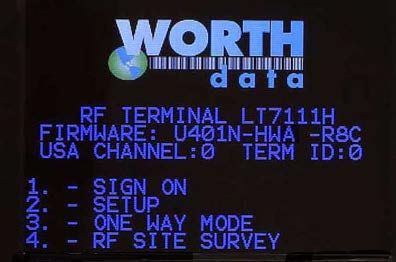
You should see the messages as shown below during the installation.
Click on “Yes” to install the Hardware Utilities Setup

Select the language and click OK,

Click the Install button to install the software. The program will then install on your system.

During the installation, you will see also see a dialog for installing the USB drivers. You will not see this message if you have already
installed the latest drivers. Click on Install and continue.

                                                                    4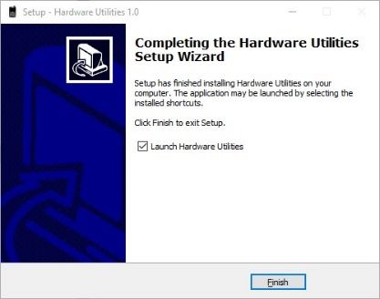
Once it completes the installation you should then Click on the “Finish” button, and it will Launch the Hardware Utilities - at this point
you can connect the

                                                                    5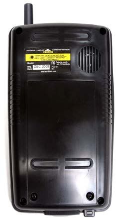
Step 5: Running Hardware Utilities
Once Integrated Hardware Utilities has completed installation you should find a program called “Hardware Utilities” in the startup
menu. Go ahead and start Hardware Utilities. A window similar to the one shown below should open.

Click on the button labeled “7000 RF Terminal”. The RF Terminal options should now be listed in the upper left pane with the first
option highlighted for “Test Program”.

If the Base is already connected and powered up then go ahead and press the “Find Base Station and Run Test Program” button.

The program will first hunt for the Base and when found it will launch the Test Program. If the Base cannot be found refer to the Base
Installation Chapter for troubleshooting tips. The Test Program window should look like this:

                                                                  6
Now you can power up the RF Terminal and select option #1 to SIGN ON. The status window should show that the Base received the
sign-on request along with some information about the RF Terminal and the prompt that is being sent to the RF Terminal in response
to the sign-on. The prompt should now show up on the RF Terminal.
You can enter some data using the RF Terminal keypad like “555” and press enter or scan a bar code. The entered or scanned data
should appear in the status window as shown below.
7You are now up and running. You can continue to enter data or scan bar codes and observe the transactions in the status window.
This demo gives you a basic idea of how the RF Terminal system works. Additional detailed information on creating your own appli-
cations can be found in the Programming section. When you are done entering data you can either press the F1 key to sign-out or
press the On/Off key to turn Off the RF Terminal. You should see the following screen when you sign out.
8Chapter 1: Installation
Components
The components in your RF Terminal system will vary according to the configuration of your system. Your RF Terminal ship-
ment should contain at least:
• An RF Terminal LT7XXXX.
• C25 Micro USB Cable – for programming and voice prompt upload.
• F17 Micro USB Power Supply – battery charger with adapter cable.
If Base Stations were ordered with your system, you should receive at least:
• A Base Station – B5011, B5021V or B5021R
• A USB cable (C21-2), or a Serial Cable (F36 or F34)
• An Optional Power Supply – Needed for use with the F36 or F34 Serial Cables and non PoE Ethernet (No Power Supply is
needed for USB or PoE Ethernet connections)
• A Relay Test Cable and junction connector block if ordering bases as Relay Stations.
Installation Sequence
1. Start with one Terminal and Base Station. Get everything working with the single terminal and base and then add other
terminals, being certain that all terminals have unique Terminal IDs. After all terminals are working, add the first relay. Then
add remaining relays, remembering to: 1) assign Relay IDs, and 2) set the jumpers of each relay to terminated or not termi-
nated properly.
2. All equipment is shipped with the default setting of Channel 0, Terminal ID 0, and Relay ID 0. Unless you have other Termi-
nal/Base configurations already operating on that channel, you probably don’t need to change the channel.
3. A Base and a Relay are the same product. A jumper change is all that is required to use a Base station as a Relay. See Chapter 3
for details.
4. Without attaching the Base Station to the computer, and with only the power supply plugged in the base, you can perform a site test
to be sure you have adequate coverage and the radios are working perfectly. (See Chapter 4).
5. Now connect the Base Station to the computer’s USB or serial port. Be sure to turn OFF all handshaking on the COM port used; in
Windows, go to Start Menu, Settings, System, Device Manager, Ports (COM and LPT).
6. Now run one of the RF Terminal demo programs found on our website to validate that everything is working. If you have prob-
lems, refer to the Trouble Shooting Section.
Connecting the Base Station
How it works…
The RF Terminal transmits data to the Base station, which in turn transmits the data to the host serial port. The computer software
reads the data coming through the serial port and processes the information accordingly. When the computer software running on
the host has a task for the terminal, it transmits data out to the serial port, which then passes this data on to the Base station. The
Base station then broadcasts the message to the terminal, causing the terminal to display the message to the user.
The B5021 is the same as the B5011 except the relay port on the B5011 has been replaced with an Ethernet port. Therefore, the
B5021V does not support operation as a relay – for Ethernet relay setups you will need a B5021R Base Station and a B5021R
Ethernet Relay. On all B5021V and B5021R units the Ethernet port supports Power-over-Ethernet (PoE) standard 802.3af which
allows you to run a single cable to the B5021 for more flexible installation options. An optional 802.3af compliant power injector
is required to supply power over the Ethernet cable to the B5021. The Ethernet port on the B5021 supports 10/100 Mbps opera-
tion.
9Connecting the Base station (B5011 & B5011R) to an RS-232 Serial Port…
If you specified a 9 pin cable (part #F36) or a 25 pin cable (part #F34) when you ordered your Base station, simply plug the RJ45
end of that cable into the COMPUTER port on the Base station, and the 25 or 9 pin end into your computer’s serial port. If you
are not connecting to a PC, see Appendix C for cable and serial pin-outs.
If you are using an extension cable and are having problems, test the cable by:
1. Connecting the Base station without using the extension cable. Simply plug in the F36 or F34 cable that came with
the Base.
2. If the Base works with only the F36 or F34 cable in place, add in the extension cable without changing the physical
location of the Base station. If the extension cable appears to be the culprit, check to be sure that Transmit lines are
connected to the Receive lines.
Connecting the Base station (B5011 & B5021R) to a USB Port…
The B5011 and B5021R uses a standard USB type B receptacle and requires a USB A-B cable to connect it to the host computer or
hub. The B5011 & B5021R can be connected directly to the host computer with a USB cable, or to a self-powered hub (hubs that
have their own power supply).
You need to connect to a full power USB port (0.5A) typically these are the motherboard connectors on a desktop computer. You
will need a power supply if you are connected to a low power USB. Many laptops, all-in-one computers, and some of the newer
micro form factor computers may only have low power USB ports. A powered USB hub will work in those situations.
When connected for the first time you will need to install the USB virtual com port driver. If the driver is not found automatically
it can be downloaded from the Worth Data website (https://www.barcodehq.com/downloads.html). Drivers are available for most
versions of Windows including 11, 10, 8, 7, Vista and XP plus Linux and Mac OS X. Once the driver is loaded a virtual com port
(VCP) is created. The host program will use this COM port to communicate with the Base. You may need to change a jumper to
configure the B5011 to use USB instead of RS-232. Both parts cannot be used at the same time. JP9 selects the port to be used to
connect to the host computer. It is located near the USB port on the PCB.
Configuring the Base station’s serial settings…
After connecting the Base station to your serial port, or by USB, you may need to configure the serial settings on the Base station
to match those required by your software. The default settings are:
• 9600 baud
• No parity
• 8 data bits
• 1 stop bit
• “None” protocol setting
You may want to increase the baud rate for performance. If you want to change any or all of these settings, see Chapter 2 for
details on configuring the Base station using the Integrated Hardware Utilities.
Connecting the Base station (B5021V) to Ethernet…
The B5021V Base Station has a standard 10/100 Ethernet port with 802.3af Power-over-Ethernet (PoE). If you wish to use the PoE
feature, set JP11 (located near the power jack) to the VPOE position. A virtual COM port (VCP) program is available that will
generate a VCP on your PC so that the B5021 Base Station will look just like it was connected to your computer via a serial cable
and is compatible with existing host software written to communicate with the Base by serial. This gives you the advantage to lo-
cate the B5021 in a remote location on your network and not have to run a serial cable from the Base to the host PC running the
application software. You can download the VCP program along with setup instructions from the Worth Data website:
https://www.barcodehq.com/downloads.html
10Installation
1. If you plan to power the B5021 using an 802.3af compatible power injector you must set JP11 on the B5021 to the VPOE
setting. JP11 is located near the DC jack in the upper right hand corner of the PCB. If you are using the supplied 5V power
supply then no change is required.
2. Power up the B5021 then connect a CAT5 cable between the RELAY/NET port of the B5021 and a hub or switch that is on
the same network as the computer to be used to configure the B5021 for the first time. The green LED on the B5021 Ether-
net jack should turn on to indicate that the Ethernet port is active. The yellow LED will blink to show Ethernet activity.
3. The next step is to configure the B5021’s Ethernet port for either DHCP or static IP address operation. The default setting is
DHCP. You can skip the next step if you wish to use DHCP to set the IP address of the B5021.
4. The “DeviceInstaller” program is used to configure the Ethernet port on the B5021 and can be downloaded from the Worth
Data website. After installation the DeviceInstaller program will be located in the Lantronix folder of the Start Menu. Next
run DeviceInstaller and you should see “xPico” automatically appear in the right hand window with its IP address and MAC
address. If not, verify that the B5021 is powered up and connected to the same network as the host computer running De-
viceInstaller. The green LED should be solid ON and the yellow LED should be blinking.
5. Single click on “xPico” in the right window then “Assign IP” from the top menu bar. The “Assign IP Address” window
should open. Select “Assign a specific IP address” if you want to use a fixed IP address for the B5021. The next screen will
prompt you for the static IP address you wish to use, the subnet mask and gateway of your network. This information is
available from your IT department. Once the IP address is configured you can close the “DeviceInstaller” program.
6. A com port redirector (CPR) program is used to map a virtual com port to the B5021. This will allow you to use any existing
B5001 program with the B5021 by simply setting the com port of the host application to match the virtual com port set by the
“CPR Manager” program. The CPR Manager program should be installed on the computer that is running the host program.
Once installed, the host program will be able to communicate with the B5021 anywhere on the network. The CPR Manager
program can be downloaded from the Worth Data website. After installation the CPR Manager program will be located in
the Lantronix folder of the Start Menu.
7. After running DeviceInstaller to configure the IP address of the B5021, run CPR Manager to configure the virtual COM port
to be assigned to the B5021. Click “Search for Devices” to find the attached B5021 which should then be listed at the bottom
pane under “Device List”. Next click “Add/Remove” to select the virtual COM port to assign to the B5021. Put a “check” in
the box for the desired COM port then click “OK” to close the window. The selected COM port should now be listed in red
in the left “Com Ports” pane and also in the “Com Port List” pane.
8. Click on the new COM port in the left pane. The “Settings” pane should open on the right. The text will be in red since the
settings have not yet been saved. If the “Service” & “Host” table is empty, click on the IP Address of the B5021 in the De-
vice List in the bottom pane to add the B5021’s IP Address to this COM port. Lastly click “Save” from the top menu bar to
save the settings. The text should turn from red to black and a virtual COM port should be created with these settings. You
can verify the creation of the virtual COM port by checking the Ports listed in Device Manager. The B5021 port will be
listed as a “Lantronix CPR Port”.
9. Since CPR Manager loads a VCP driver you will not need to run CPR Manager again unless you wish to change or remove
the virtual COM vorts on this computer.
10. If you wish to remove the virtual COM port from this computer click “Add/Remove” then uncheck the virtual COM port
assigned to the B5021. Click “OK” to close the window then “Save” to remove the port from this computer.
Base station channel…
To determine what channel your Base station is set to, plug in the power supply and watch the LED light on the front of the Base
station. The LED will blink “the channel + 3” times.
For example, the default channel is 0. On power up, the LED on a Base station set to channel 0 would blink 3 times. A Base sta-
tion set to channel 5 would blink 8 times.
If this is the only Base station operating, leave the channel at 0. If you have other Base stations in the area and need to change the
channel, see Appendix A; Channel and Jumper Changes for details on how to open the Base station and set the rotary switch
inside to the desired channel.
11RF Terminal Operation
Using the RF Terminal keypad…
The RF Terminal is turned on by pressing the green ON/OFF button located in the upper left-hand corner of the RF
Terminal keypad.
It is a good idea to fully charge the RF Terminal before you use it the first time to make sure the battery charged. See
below for more information on battery charging.
The RF Terminal has a Shut Down Time feature that allows you to determine the length of time the RF Terminal must be inactive
before automatically shutting down to conserve battery power. When the RF Terminal shuts down, simply press the ON/OFF
button to resume operation.
The keypad is custom designed for the RF Terminal operations. It has numeric and control keys in the non-shifted state, and alpha
characters in its shifted state. You can readily determine if the SHIFT is on by the cursor on the display. When SHIFT is on, the
cursor is a large rectangle. When SHIFT is off, the cursor is a narrow underline character. For all prompts which ask for a YES or
NO response, the ENTER key, is the YES reply, and the 0 (zero) key is the NO reply. As you key data, you will see each charac-
ter displayed on the screen. If you make a mistake, you can delete the last character by pressing the DELETE key, or you can
clear all characters displayed on the screen by pressing the CLEAR key.
Battery Life Indicator
The RF Terminal detects low battery and displays the following message:
LOW BATTERY
Charge Battery
Hit Any Key_
At this point you have approximately 10% of battery life remaining. You should complete what you are doing and charge the bat-
tery soon. When the battery is too low to operate the unit properly another message is displayed:
Battery too Low to Operate
Hit Any Key to Power Down
If you turn it back on without charging batteries, you may experience constant beeping, intermittent scanning, and very irritating
symptoms that look like equipment failure.
The RF Terminal also has a battery life indicator that can be accessed while operating in ONE-WAY or TWO-WAY mode or
while in the MENU. To display the remaining battery life of the battery (as well as the date and time) press the STATUS key:
mm/dd/yy hh:mm:ss
BATTERY: |||||||||||||||||||| zz%
R7Uxxx ID=0 CH=0 RL=N
SC=N RF=8C C=N
zz=percent in numbers i.e. 99, 10, 05
Press the STATUS key again to resume processing.
The lifetime of the RF Terminal's Li-Ion battery is 500-1000 charge cycles. If the battery runtime seems to be significantly shorter
than when the device was new, the battery should be replaced. If you have the optional “gun” handle with the extended battery
then both batteries should be replaced at the same time. The main battery is a common digital camera battery sold as Fujifilm NP-
120 or Pentax D-LI7. We use a high quality Japanese Li-Ion cell in our OEM pack that we supply with the RF Terminal. You can
obtain a replacement from Worth Data (P/N: L02) . Our pack is rated at 1950 mAh and provides the longest runtime available. Do
not use a battery pack of unknown quality or origin. Doing so can risk damage to your unit. The optional handle battery is custom
made for Worth Data and must be ordered from us.
Your old battery should be recycled. You can get free recycling information at: http://www.rbrc.org/
12To change the internal battery:
1. Turn OFF the RF Terminal.
2. Remove the battery holder door on the back of the RF Terminal by removing the two screws holding the door in place..
3. Remove the old battery and insert a new one, making sure to orient the battery with the battery contacts facing the bat-
tery connector.
4. To replace the optional handle battery, remove the 2 screws holding the handle in place. Unplug the handle battery as-
sembly.
5. Replace the battery door and screws and turn the reader on using the ON/OFF switch.
6. Sign ON and resume your application.
Recharging the RF Terminal Battery:
1. With the RF Terminal shut off, plug the F17 power adapter into a wall outlet, and plug into the RF Terminal using the
supplied C25 Micro USB cable.
2. The RF Terminal will turn On and display the following message:
Charging Battery
Please Wait………..
3. When the battery is fully charged after 2-4 hours the following messaged is displayed:
Battery Charge Complete
4. The unit will remain ON for a half hour or so after the charge cycle has completed and then turn OFF.
5. If you press the POWER key while the unit is charging, nothing will happen.
6. If you press the POWER key after the unit has turned OFF after completing a charge cycle and the charger is still at-
tached, the “Charging Battery” message will display again and a charge cycle will begin.
7. It will take about 2 hours to fully charge a unit with a single battery and about 4 hours to fully charge a unit with the op-
tional handle battery.
8. Do not charge the battery if the Terminal is very hot or very cold since this will give a false reading on the condition of
the battery and it may not get charged properly.
9. You cannot operate the unit when the charger is attached, except to charge the battery.
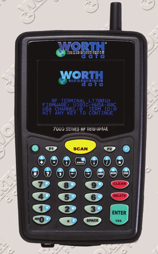
13RF Terminal Menu Functions
Upon power-up, the RF Terminal displays the following opening screen:
(The opening screen can be bypassed upon power up. See Chapter 2)
On second line on the screen, FIRMWARE: Uxxx, gives the firmware revision number. The letter U indicates USA frequency.
Rzz refers to the version of the radio processor firmware.
• HWyy indicates the version of the hardware.
• USA CHANNEL: 0 refers to a Terminal set to RF channel 0. You can use 0-5 for the RF Channel
• TERM ID: 0 refers to the current Terminal ID. The default setting is 0. Every Terminal must have a unique ID.
• Press the 1 key to SIGN ON to a two-way communication host computer program through the Base station.
• Pressing 2 enters the Setup Mode for the RF Terminal or Base station.
• Press 3 to enter ONE-WAY mode. ONE-WAY mode allows the RF Terminal to transmit data to the host computer without
prompting from the host computer program – we call this “dumb” data entry. (If you want a Terminator Character on the
bar code, you will have to enter a Postamble using the Setup Menu). ONE-WAY mode is also useful for demos, as it does
not require any interaction from the host computer.
• Press 4 to enter RF SITE SURVEY. SITE SURVEY is an excellent way to assess your RF communication in any area. It
can help you determine the best place to locate your Base station for maximum RF performance as well as troubleshoot
problems that may relate to range or interference.
You can back-out of any mode or prompt by pressing the F1 key. For example, if you select SETUP MODE but really want
ONE WAY MODE, press the F1 key to take you back to the menu. The F1 key on the RF Terminal keypad works like the ESC
key on the PC – it will usually get you out and back to the previous step. You can use the F1 key to exit and SIGN OUT when
using a Two-Way communication program running on the host computer.
The entire mode menu can be skipped (see Chapter 2; RF System Setup), causing the RF Terminal to automatically SIGN-ON
or go to ONE-WAY mode on power up.
14Installing the Integrated Hardware Utilities Software
The RF Terminal system works with the Integrated Hardware Utilities that can be downloaded from our website at
https://www.barcodehq.com/downloads.html. The following tools and programs are available.
Windows Demo Programs and RF DLL Programmers Library
• .Net Component
• Demo Programs in VB, Access, and Delphi
• 16 bit and 32 bit DLLs
• VB DLL-based QL3 printer demo program
Integrated Hardware Utilities
• Voice Manager
• Base Configuration
• Terminal Configuration
• Firmware Loader
• Test Program
• Cloning
ActiveX Tools
• Serial Interface (includes Excel and VB demos)
• TCP/IP (includes VB/Access and Delphi demos)
DOS/BASIC source demo programs (requires GWBasic or QBasic)
Running the Test Program…
The test program is provided to help you test your RF Terminal with a two-way communication program. Simply connect the
B51x0 to the host computer and start the program. It will search for the Base and start the demo.
15Chapter 2: RF Terminal Setup
The RF Terminal can be configured using the Terminal Setup Menu. Most users do not need to change anything in the setup. The
most commonly changed setup parameters are the Terminal ID (especially if you have more than 1 terminal) and the Channel (if
you are adding an additional Base station).
Factory Default 1D RF Terminal Configuration
Parameter Default Setting Parameter Default Setting
RF Configuration RF Channel - 0 MSI /Plessey Code MSI - OFF
Terminal ID - 0 MSI with 1 mod 10 - OFF
Security code - OFF MSI with 2 mod 10 - OFF
Skip opening screen - OFF MSI with mod 11/mod 10 -
OFF
Control Keys Only - OFF Transmit check digit - 0
Auto Check Back - 00 Plessey - OFF
Codabar
Codabar - OFF
Code 3 of 9 Code 39 - ON
Full ASCII - ON CLSI format - OFF
Accumulate Mode - ON START STOP Char - OFF
Transmit Start Stop - OFF Code 128 Code 128 - ON
MOD 43 Check Digit - OFF UCC/EAN-128 - OFF
Transmit MOD 43 - OFF Databar / RSS-14 Databar / RSS-14 - OFF
Caps lock - OFF
Decode Option - 0
2 of 5 Code Interleaved 2 of 5 - OFF Code 93 / Code 11 Code 93 - OFF
Check Digit - OFF Code 93 full ASCII - ON
Transmit Check Digit - OFF Code 11 - OFF
Standard 2 of 5 - OFF Code 11 Check Trans - 0
2 of 5 Length - 06 Bluetooth Settings Optional Feature
UPC-A EAN 13 UPC/EAN ALL - ON
Supplements - OFF Bluetooth Device List
UPC-A NSC - ON PIN - none
UPC-A check digit transmit- Time & Date Settings Date Format - USA
ted - ON Year Output – 2 digits
EAN-13 country code trans- Shut Down Time – 5 min
mitted - ON Speaker Options Beep Volume - medium
UPC-E EAN 8
EAN-13 Check - ON Beep Tone - 2
ISBN EAN-13 mode - OFF Voice Volume - medium
UPC-A as EAN-13 - OFF Keypad Tone - ON
UPC-E First Char - OFF Laser Options Double Decode - OFF
EAN-8 First Char - ON 4.5 Second Beam - OFF
UPC-E Check Digit - OFF Aiming Dot Duration – 0 sec-
onds
EAN-8 Check Digit - ON
UPC-E Expanded Trans-
mission - OFF
LCD Settings 4/6 Line Legacy Mode -OFF
UPC-E1 - OFF Background Color – 1 (black)
Other Bar Code Storage Tek Label – OFF
Options LabelCode 5 - OFF Text Color – 2 (blue)
LabelCode 4 - OFF Brightness – medium
Barcode IDs - OFF Brightness Timeout – 5 sec
Factory Default 2D RF Terminal Configuration (In addition to 1D above)
PDF 417 - ON Aztec Code - ON
Micro PDF 417 - ON Aztec Runes - OFF
Codablock F - OFF QR Code - ON
Data Matrix ECC-140 - OFF Micro QR - ON
Data Matrix ECC-200 – ON Maxi Code - ON
(1D) POSTNET – OFF (1D) INTELLIGENT MAIL - OFF
NEGATIVE BARCODE - OFF
1617
Using the Setup Menu on the RF Terminal
  The RF Terminal can be setup via the Terminals' keypad by entering Setup Mode from the main menu. Press the On/Off key.
  You should now see the MAIN MENU message:

  Press the 2 key. The next menu allows you to choose which item to configure:

                   RF TERMINAL SETUP
              RF CONFIGURATION - - - - - - - - -           1
              BAR CODE OPTIONS - - - - - - - - -           2
              DATE & TIME SETTINGS - - - - - -             3
              SPEAKER SETTINGS - - - - - - - - -           4
              LASER SETTINGS - - - - - - - - - - -         6
              LCD SETTINGS - - - - - - - - - - - - -       7
              OTHER SETTINGS - - - - - - - - - - -         8
              SYSTEM TOOLS - - - - - - - - - - - - -       9
              DONE/EXIT - - - - - - - - - - - - - - -      0

  Select the option you want to set or verify or press 0 or the F1 key to exit back to the MODE MENU.

  The groups in the keypad Setup Menu contain the following setup parameters:
                    Setup Group       Parameter                Setup Group     Parameter
                    RF Configuation   RF Channel               Speaker         Beep Volume
                    1                 Terminal ID              5               Beep Tone
                                      Security Code                            Voice Volume
                                      Skip opening screens                     Keypad Tone
                                      Control Keys Only        Laser           Double Decode
                                      Auto Check Back          6               4.5 Second Laserbeam
                                      Relay Existence                          Aiming Dot Duration (LT7101x)
                                      Beep In Auto Check                       Filter Setting (LT7111x)
                                      Shutdown In Auto Chk
                    Bar Codes         Code 3 of 9              LCD             4 Line Legacy Mode
                    2                 UPC-A, EAN 13            7               6 Line Legacy Mode
                                      UPC-E, EAN 8                             Background Color
                                      Code 128                                 Text Color
                                      2 of 5 Codes                             Brightness
                                      Codabar                                  Brightness Timeout
                                      MSI/ Plessey             Other           Preamble
                                      Code 93 / Code 11        8               Postamble
                                      Databar / RSS / Others                   Characters
                    Date/Time         Time                                     Encryption Key
                    4                 Date                     Bluetooth       Bluetooth Device List
                                      Date Format              9
                                      Year Output              Bluetooth PIN   Bluetooth PIN ____
                                      Shut Down Time           A

                                                               18
Once you have selected a group to edit, you will see each parameter displayed in the order listed above. Use the next section of
this chapter as a reference for all RF Terminal Setup Parameters.
RF Configuration
Default settings are shown in bold type.
The RF Terminal will typically require no setup changes except, Terminal ID (if more than one terminal) and enabling bar codes to be read other
than UPC or Code 39.
RF Terminal ID
Default ID 0
Available IDs 0-9, A-Z, a-z, - =
• Every terminal needs a unique Terminal ID. The default Terminal ID is always shipped as 0. If you have more than one RF
Terminal assigned to a Base Station, you must be sure that each RF Terminal has a unique Terminal ID, (otherwise you will
have big troubles including false error messages). The Terminal ID is always displayed on the Start Up screen when you
power up the terminal. There are 64 Terminal IDs available - 0-9, A-Z, a-z, and the special characters "-" and "=". To change
the Terminal ID, select option 2 on the keypad after which a box will appear where you can enter the desired Terminal ID.
Enter one character for the Terminal ID.
RF Terminal Channel
Default Channel 0
• The terminal's radio operates by "frequency hopping" spread spectrum. The radios hop from one frequency to another using a
pseudo-random sequence. The radio goes through 26 different frequencies and then repeats the sequence – all in the 902-928
MHz band at 250 milliwatts of power. Different sequences define the channels. It is possible to have more than one RF Network
in the same area, providing each RF Network is on separate channels to avoid interference and general confusion.
• The default Channel is always shipped as 0. There are 6 channels in the USA. The Channel can be set by pressing the 1 key
when in the RF Configuration menu. Each time you press the 1 key the Channel will increment through the 6 possible channels.
All Terminals, Base Stations and Relays in the RF Network must be set to the same channel. The channel is always displayed on the
Start Up screen when you power up the Terminal. It is possible to have more than one RF Network in the same area, providing each
RF Network is on separate channels to avoid interference and general confusion.
Security Code
Security Code OFF
Available security codes 3 characters
• A Security Code can be utilized to minimize the possibility of a Base Station listening to data from a Terminal that is talking to
a different Base Station. A Security Code can also prevent interference from having many Base Station/RF Terminal configura-
tions in one area; i.e. a merchandise mart with multiple vendors all running RF Terminal networks.
• A Security Code consists of 3 characters - any combination of ASCII 33 - ASCII 126. This allows for the possibility of more
than 830,000 different character combinations. The characters are entered using the bar coded FULL ASCII MENU provided in
Appendix O; ASCII Code Equivalent Table.
• Once you press 3 to enable the Security Code, you will see 3 boxes appear where you can enter the desired security code. Press-
ing the CLEAR key will reset the Security Code to the default value which is OFF. You can enter any key on the keypad. If you
press the shift key the cursor will turn RED and you can enter any of the shifted values on the keypad.
• You must also enter a matching security code into the Base using the Hardware Utilities program.
To enter characters that are not on the keypad, use the FULL ASCII MENU provided in Appendix O.
Skip Opening Screens
OFF
Go to Two-Way (TWO WAY)
Go to One-Way (ONE WAY)
• Many users want to skip the opening screens and go directly to TWO WAY or ONE WAY communication once their pro-
grams are fully operational. Selecting TWO WAY or ONE WAY will automatically take the operator to the corresponding
mode and into your application, skipping the usual Mode Menu. If you want to return to the Mode Menu at any time, simply
press the F1 key.
19You can also read