A Knowledge-Based CAD Modeling Paradigm for Indian Traditional Filigree Jewelry - CAD Journal
←
→
Page content transcription
If your browser does not render page correctly, please read the page content below
207

 A Knowledge-Based CAD Modeling Paradigm for Indian Traditional
                       Filigree Jewelry

                                Sonu Mathur1     and Vishal Gulati2

      1Guru   Jambheswar University of Science and Technology, Hisar, sonumathur@gjust.org
    2Guru   Jambheswar University of Science and Technology, Hisar, vishal_gulati_in@yahoo.com

                     Corresponding author: Sonu Mathur, sonumathur@gjust.org

        Abstract. The present work aims to develop a knowledge-based parametric CAD
        modeling system to create Indian traditional filigree jewelry designs. Today,
        developments in CAD technologies are towards reducing the time and efforts of
        designers required in modeling. Indian traditional Filigree jewelry is delicate metal
        craftwork representing twisting or curling of pliable wire and shows the beauty of
        local craftsmen’s traditional workmanship involved in making this type of decorative
        embellishments that result in a very precise and delicate model. Traditional
        craftworks involve much skill, effort, and time, so upcoming generations are not
        interested in their respective traditional works. The traditional knowledge base of
        Filigree jewelry is incorporated in the CAD system's programming environment by
        defining some shape grammar rules and logical rules to control jewelry attributes.
        Parametric modeling has great potential to develop customized CAD tools for
        automation in generating 3D models of handicraft products in a virtual environment.
        By using knowledge base rules, geometrical models can be designed beyond a
        conventional design. This knowledge-based jewelry modeler is developed using the
        Microsoft Visual Basic Programming environment in SolidWorks API.

        Keywords: Parametric Modeling, SolidWorks API, Knowledge-Based Modeling,
        Indian Traditional Jewelry.
        DOI: https://doi.org/10.14733/cadaps.2022.207-219

1   INTRODUCTION
Traditionally, the Indian jewelry designing process involves two specialized tasks: drawing-by-hand
and manufacture-by-casting. These tasks are regarded as ancient traditions passed on through
generations. These tasks involve much skill, effort, and time, so upcoming generations of jewelry
makers are not interested in their respective traditional works. They feel a lot of anxiety due to the
growing expectations in terms of novelty in designs and high-quality jewelry. Their lack of
indigenous knowledge in this craft sector has let down the interest in producing traditional jewelry.
As a result, the traditional jewelry business is at the edge of fall down.

                                        Computer-Aided Design & Applications, 19(2), 2022, 207-219
                                            © 2022 CAD Solutions, LLC, http://www.cad-journal.net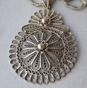
208

    Traditional jewelry designing depends on craftsman experience and artistic sense. The
innovation of jewelry designs requires expertise, particularly generating new design ideas. As
jewelry designing is inherently a knowledge-intensive activity, a great deal of emphasis is needed to
use its knowledge base in computer-aided design [2]. But, it is realized that there is often
reluctance among jewelry makers to embrace the CAD/CAM technology because of fear of losing
their heritage style of craftworks. Consequently, in this work, an idea of convergence of craftwork
and technology has been implemented in jewelry making as a fusion of computer-aided jewelry
designing with traditional manufacturing by casting. The craft people are CAD illiterate persons.
Therefore, an interactive and user-friendly Graphical User Interface (GUI) is needed to develop in a
CAD programming environment that accepts craftsmen's data input and interacts with CAD
software.
    The present work aims to develop a CAD tool to produce Indian traditional filigree jewelry
designs using knowledge-based parametric CAD modeling. A knowledge-based approach encourages
the virtual jewelry designing to provide parametric and dynamic modeling through which geometric
manipulations can be carried out to alter designs in a CAD system. This will help to cut down the
jewelry designing time and as well as production cost. Furthermore, this system provides a way to
automate craftsmanship and extend CAD system features to use it beyond limits. Such CAD
customization supports the creative jewelry design process and allows the designer to create novel
2D and 3D virtual designs; to prolong this Indian jewelry sector.
    The jewelry knowledge base is a repository of rules, theory, assumptions, regulations, concepts,
details, etc., and these rules can generate geometric models in a more flexible and controlled
system. Traditional knowledge base, which captures the jewelry design attributes and process
information, is programmed in CAD environment so that it can be retrieved whenever required. The
automatic jewelry CAD model generation is carried out with a predefined framework that utilizes
craft knowledge, traditional artistic sense in design computations, and parametric modeling in CAD.
Visual Basic for Application is employed in SolidWorks customization to perform parametric modeling
and the macro codes to generate the jewelry CAD models.

2   RELATED WORK
Today, developments in CAD technologies reforming the jewelry designing process and several
industry-specific CAD software's are available in the market for jewelry modeling to create jewelry
masterpieces [1], [11], [14], [18]. These systems provide advanced features in modeling and
rendering of some common types of jewelry (such as earrings, rings, bracelets, necklaces, cufflinks,
etc.) with gems and relief settings. All the commercial CAD systems are capable of converting CAD
models into RP models. Traditional pieces of jewelry are significant due to the technical perception
involved in the jewelry making process and the presence of a well-developed artistic sense.
Traditional crafts are the results of continuous improvement and innovations by local craftsman's
with aesthetic beauty. In traditional craft products, the major difficulty is understanding of nature
and characteristics of designs [10]. Recently, jewelry designers incorporate techniques based on
craftsmanship, like fine art, decorative art, and applied art [7]. Handicraft designing using modern
CAD tools requires much more skills other than traditional knowledge [24]. The task of jewelry
designing through these CAD systems can only be performed when jewelry makers have expertise in
the inherent mathematical mechanism of these systems as the modeling is based on geometrical
transformations [16]. Since most traditional jewelry makers are novice CAD users, they are not
proficient in designing with CAD. Consequently, these conventional CAD systems are not finding
themselves successful in impacting the Indian traditional jewelry sector.
    Because of the above fact, some customized jewelry CAD tools in which a set of jewelry
modeling steps are incorporated programmatically by customizing a CAD system. A CAD modeler is
developed to produce forming tools using parametric voxels for stretch-formed jewelry in which
design patterns are embossed on thin metal sheets [8]. The voxels are placed in different positions
as per the jewelry design required. In the traditional craftwork, the freehand sketching is an inherent

                                        Computer-Aided Design & Applications, 19(2), 2022, 207-219
                                            © 2022 CAD Solutions, LLC, http://www.cad-journal.net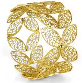
209
element in design and enables visualization of idea using pencil and paper. In WrapIt, the input line
drawings are decomposed into small smooth segments of curves and jigs are printed to assist novice
users in bending and wrapping of wires [9]. The Sketch2Jewelry [23] is sketch-based modeling CAD
tool which retrieves feature based on sketch data and some procedural rules are applied to compute
shape/curve parameters. A parametric feature-based CAD interface is developed for the design of
traditional pierced jewelry, which is termed as ByzantineCAD [19]. Structural elements are
parameterized as a shape of rectangular parallelepiped with carving around a hole and the user
participation is limited to input elements parameter. Fractal constructing Iterative Function System is
utilized to generate ring and jewelry designs by using motif curve as fractal geometry [20], [22].
The fractal curve gives a new aesthetic to the ornamental products. However, these tools would not
produce traditional jewelry masterpieces for jewelry makers who are CAD illiterate for facilitating
their design work.
It is revealed that these customized jewelry CAD tools may not be the whole substitute for
jewelry designing for inexperienced jewelry makers who do not have artistic talent in their field.
Even after getting knowledge of utilizing these customized CAD tools, unskilled jewelry makers
would not be able to produce pleasing jewelry designs as jewelry making is a field that still largely
relies on individual skills. Using interactive 3D modeling, the designer can re-construct sculptures
surfaces from unstructured or ambiguous data by parameterization of model data [3]. Computer
helps in shape optimization and various simulations to evaluate the model as sound from aesthetic
as well as technical [17]. Parametric modeling and knowledge base systems [16] have great
potential to develop customized CAD tools for automation in generating 3D jewelry models in a
virtual environment [4], [12]. The knowledge base system captures the design attributes and
process information of a model to support decision making in design process. This work targets a
different group of novice crafters interested in incorporating CAD tools in designing their unique
jewelry with hands-on manufacturing techniques.
3 PARAMETRIC MODELING IN JEWELRY
Recent developments in techniques, such as digital tools and modern techniques in jewelry
manufacturing have encouraged researchers to study the industry’s features. In modern CAD
systems, the basic structural elements are defined through the parametric definition and some
specific attributes are applied in the modeling of complex jewelry designs [5]. Most commercial CAD
packages use the parametric design concept and have a characteristic: the geometric changes are
made by controlling the variables [15], and from a single motif, it is possible to make endless
variations to the shape.
All over the world, the peoples choose the jewelry products having the traditional appearance
and these traditions have certain motifs. The designs are created by the artistic imaginations of
jewelry makers. Due to design and motif variation in traditional designs, the CAD software available
is unsuitable for traditional jewelry designs. In traditional jewelry designing, using parametric design
methods, new jewelry designs can be prepared with new textures and forms, increasing
modernization [16]. Today, personalized products are more preferred by peoples, which are also
fulfilled by parametric jewelry modeling.
4 A KNOWLEDGE-BASED MODELING APPROACH FOR FILIGREE JEWELRY
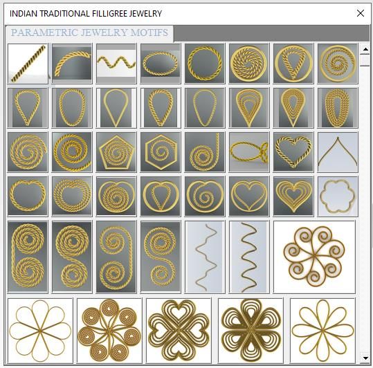
Filigree jewelry is famous in Orissa and Andhra Pradesh states of India. It is a delicate craftwork
representing the twisting of wire threads, usually of gold, silver, and aluminum, into a design.
Traditionally, a twisted wire strand is created by twisting two or three plain wires together. Further,
twisted wire strand is crimped into a motif (usually have geometries like jails, curls, cycloids, spirals,
etc.), filled in a frame (usually made of single wire and with a theme like leaves, rosettes, flowers,
animals, especially butterflies and birds) and endowed by soldering with frame (shown in Fig. 1).
Computer-Aided Design & Applications, 19(2), 2022, 207-219
© 2022 CAD Solutions, LLC, http://www.cad-journal.net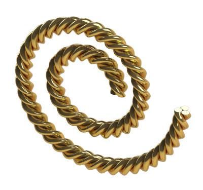
210

                               Figure 1: Traditional Filligree Jewelry.

One of the knowledge base of filigree jewelry is to identify the motifs used in this jewelry tradition.
By exploring the designs of filigree jewelry in India, more than ninety types of motifs are identified.
These traditional motif geometries have been defined in terms of parametric mathematical
equations in a CAD system's programming environment (Fig.2).
    Further, it is revealed, particularly from those designs created by local craftsmen, a number of
basic shaped motifs are joined into an intricate shape that is being inserted repeatedly into a frame
in every ancient jewelry design. The knowledge base here is to get how multiple motifs could be
joined to produce compound-motifs. The attribute of this knowledge base is to find number, size,
and orientation of motifs with respect to frame.

                        Figure 2: Primary Motifs Shapes of Filigree Jewelry.

Another knowledge base of filigree jewelry is to find how multiple motifs/compound-motifs could be
symmetrically placed and joined as a jewelry design (floral, peacock, rosettes, animals and birds,
etc.). One of the attributes of this knowledge base is to get the number and size of
motifs/compound-motifs to get geometrical symmetry. Another attribute of the knowledge base is to
get jewelry size so that multiple motifs/compound-motifs bounded remains in contact with the
frame.
     All traditional knowledge base is incorporated in the CAD system's programming environment by
defining some shape grammar rules and logical rules to control these attributes. Such an integration
of traditional knowledge base and CAD customization acknowledges the jewelry design automation.
The defined motifs/compound-motifs can be parametrically controlled through a user interface and
programmatically interaction in the CAD system. This enables the user to interact with the modeling
environment through the interface to get variety in geometric designs.
    This CAD paradigm has been implemented in Solidworks application programming interface,
which utilizes predefined native CAD entities (point, line, circle, spline, etc.) and operations
(extrusion, revolution, sweep, etc.) with the specific algorithm. The algorithm includes modeling

                                        Computer-Aided Design & Applications, 19(2), 2022, 207-219
                                            © 2022 CAD Solutions, LLC, http://www.cad-journal.net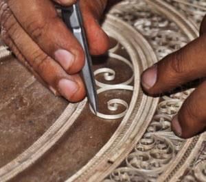
211

steps from sketching to feature-based operations to generate the desired jewelry designs in a Visual
Basic programming environment. A set of jewelry modeling steps are incorporated programmatically
by customizing a CAD system are presented.

                                   Filigree Jewelry                       Logical Rules /
                                        Designs                            Shape Rules

                     Traditional                      Knowledge Based
                     Knowledge                            System

                     User Interface                    SolidWorks API

                                                    Customization CAD

                                                    Generated Filigree
                                                     Jewelry Designs

                Figure 3: A knowledge-based modeling approach for Filigree Jewelry.

5   PARAMETRIC MATHEMATICAL DEFINITIONS FOR MOTIF GEOMETRIES
The geometry of motifs is in the form of a planar map created by simple curves and lines and can be
defined parametrically by a set of point coordinates. Motif geometries used in Filigree jewelry
designing are programmed in the CAD system by parametric mathematical definitions to implement
the concept of parametric modeling which enables user to alter the motif shapes with the change in
mathematical parameters. This sort of coordinate geometry information is fundamental to the motif's
primary position in Filigree jewelry design work.
    Parametric mathematical definitions of spiral shaped motif, heart shaped motif, pear shaped and
teardrop shaped motif which are most commonly used geometries in Filigree jewelry designs (as
shown in Figure 1) are represented in table 1.
    As an example, a parametric Archimedean spiral-shaped motif in a two-dimensional plane is
described mathematically as:
    x   rt cos(n )    y   rt sin(n )   t   0,1
                                                                                              (1)
Parameters that affect the geometry of Archimedean spiral are r, n, t, and θ. The r is the radius of
the circumscribed circle to which n turns of spiral are placed at a fixed space between turns. The
value θ varies from 0 to 2π for a complete turn.

The modeling of these shapes using parametric definitions is carried out by defining functions in
Solidworks API in the VBA programming environment. Many functions and procedures are called in
the programming environment to generate the sketch of the shape required in a parametric way. For
Archimedean spiral (Figure 4), the VBA function is:

                                                 Computer-Aided Design & Applications, 19(2), 2022, 207-219
                                                     © 2022 CAD Solutions, LLC, http://www.cad-journal.net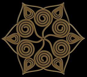
212

                      Figure 4: Archimedean spiral-shaped motif geometry.

Name of Motif     Parametric Definition of Geometry and Geometric               Jewelry Motif
Element           Shape Parameters
Ring Motif        x      r cos(t )
                  y      r sin(t )

                  r - Radius of Ring, t - 0 1
Oval     shaped   x      a cos(t )
Motif
                  y      b sin(t )

                  a - Major Axis, b - Minor Axis, t - 0, 2
Archimedean       x      rt cos(n )
Spiral Motif
                  y      rt sin(n )
                  r - Radius of circumscribed circle
                  n - Number of turns in spiral
                    - Varies from 0 to 2 for complete turn
                  t - 0 1
Logarithmic       x      re bt
                               cos(n )
                          i
Spiral Motif                bt
                  y      re
                          i
                               sin(n )

                  ri - Minimum radius of Spiral
                  ro - Radius of circumscribed circle
                     - Varies from 0 to 2 for complete turn
                             ro
                  b    log            , t - 0, 1
                                  a
Heart    shaped                                     3
                                           16r sin (2 t )
Motif             x      13 cos( )      5 cos(2 )       2 cos(3 )   cos(4 )
                  y      r (13 cos(2 t ) 5 cos(4 t ) 2 cos(6 t ) cos(8 t )
                             13 cos( ) 5 cos(2 ) 2 cos(3 ) cos(4 )
                  r - Radius of circumscribed circle to heart shaped geometry
                  t - 0, 1

                                             Computer-Aided Design & Applications, 19(2), 2022, 207-219
                                                 © 2022 CAD Solutions, LLC, http://www.cad-journal.net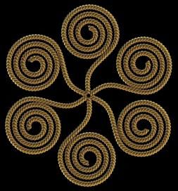
213

     Pear      Shaped          x     a cos(t )
     Motif
                               y     b sin(t )sinC (t / 2)
                               a - Width of pear geometry
                               b - Height of pear
                               c - the curvature of curve between 0 to 7
                               t - 0, 2
     Petal Motif               x     a sin(2t )
                               y     b sin(4t )
                               a - length of petal
                               b - width of petal
                               t - 0,
     Cubic         Sine        x     lt
     Motif
                               y     h sin 3 (t )
                               l - length of curve
                               h - height of curve
                                  - 2 for one cyclic turn and further increases
                               as per cycles required
                               t - 0, 1

                                    Table 1: Parametric Definition of Jewelry Motifs.

Private Function createArchSpiral(ByVal planeS As String, ByVal radius As Double, ByVal turns As Double,_
                                                                  ByVal centerX As Double, ByVal centerY As Double) As String

    Dim calX, calY As String

    calX = radius & "*t*(cos(t*" & turns * 2 * pi & "))"
    calY = radius & "*t*(sin(t*" & turns * 2 * pi & "))"
    boolstatus = Part.Extension.SelectByID2(planeS, "PLANE", 0, 0, 0, False, 0, Nothing, 0)
    Part.SketchManager.InsertSketch True
    Dim equationDriveCurve As Object
    Set equationDriveCurve = Part.SketchManager.CreateEquationSpline2(calX, calY, "", 0, 1, False, centerX,_
                                                                                                        centerY, 0, True, True)
    Part.SketchManager.InsertSketch True
    Set lastFeature1 = Part.FeatureByPositionReverse(0)
    createArchSpiral = lastFeature1.Name

End Function

6      CONCEPTUALIZATION OF TWISTED WIRE MOTIF
Traditionally in Filigree jewelry, motifs are generated in the following sequence: Firstly, twisted wire
strand is created by twisting two or three plain wires together (Fig.5 (a)) using the rotating wheel
machine called “Charkha.” Further, twisted wire strand is crimped into a motif shape, filled in a
frame (usually made of single wire and with a theme like leaves, rosettes, flowers, animals,
especially butterflies and birds) and then soldered expertly (Fig.5 (c)).

                                                        Computer-Aided Design & Applications, 19(2), 2022, 207-219
                                                            © 2022 CAD Solutions, LLC, http://www.cad-journal.net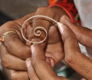
214

                         (a)                      (b)                      (c)

Figure 5: Conventional Method of (a) Making twisted wire strand (b) bending wire into motif shape
(c) placing motif in a frame and soldering.

In this CAD paradigm, modeling algorithm follows the sequence of sweeping the circular profiles of
wires along the predefined motif geometry (circle, star, pear, teardrops, leafs, oval, freeform shapes,
etc.) and then twisting the swept profiles along the same trajectory. The circular profiles of wires of
radius Rw (up to 4) are sketched on a plane which is normal to geometry of motif, in such a way
that each circle touches with its adjacent one (Table 2). Such an arrangement of profiles will result in
a twisted wire strand as it braided very tightly when swept and twisted along a motif's geometry.

                      No. of Wires in        Position of circle       Geometry of
                       Motif shape          profile w.r.t Origin      Sweep Profile

                   Frame/Single Wire                 0, 0

                                                    RW , 0
                   Double Wire
                                                     RW , 0

                                                RW , RW       3

                   Three Wire                  0, 0.2 * RW        3

                                                RW , RW           3

                                                   RW , RW

                                                   RW , RW
                   Four Wire
                                                   RW , RW

                                                  RW , RW

                      Table 2: Sweep Profiles for creating filigree frame/motifs.

                                        Computer-Aided Design & Applications, 19(2), 2022, 207-219
                                            © 2022 CAD Solutions, LLC, http://www.cad-journal.net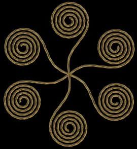
215

                                 (a)                               (b)

Figure 6: Figure 6: Modeling of twisted wire strand (a) plane for wire profile and sketching
geometry (b) sweeping and twisting of wire profile (twisted wire strand made of 3 wires).

7   MODELING PARAMETERS OF JEWELRY MOTIF
It is effortless to modify the filigree jewelry characteristics such as the number of wires, wire size,
etc., by parameterization of jewelry motifs. Motif shape parameters limit the length, width,
curvature, radius of control polygon/circle, etc. of motif geometry and modeling parameters alter the
wire size, number of wires in motif, and twist control in a jewelry motif. The modeling parameters
that not only define the motif's outline and but also characterize the twisted wire strand for motifs
are as follows:
        •   Number of wires (N: 1 to 4) in strand
        •   Size of wire (Rw) defined as radius of wires used in the strand.
        •   Numbers of turns in strand (n) measure of degree of closeness between wires.

              N=1, n=0             N=2, n=20            N=2, n=30              N=3, n=12

             N=3, n=18             N=3, n=25            N=4, n=10              N=4, n=15

      Table 3: Variation in Jewelry motif with change in modeling parameters r=6, Rw=0.25.

8   MODELLING STEP TO PRODUCE JEWELRY MOTIF/PATTERN
The user participation in design starts by picking a jewelry motif from the library of motif/compound-
motif and defining the corresponding attributes' parameter values. The user provides the values of
shape/size parameters and modeling parameter. To retain the geometric beauty, constraints are
imposed during modeling process at an early sketching level as well in features. Compound-motif is
analyzed as a combination of primary motif elements and designed with a unique theme of aligning
motifs along a specified trajectory.

                                        Computer-Aided Design & Applications, 19(2), 2022, 207-219
                                            © 2022 CAD Solutions, LLC, http://www.cad-journal.net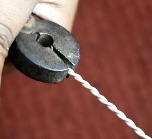
216

                           Figure 7: User Interface for Filligree Jewelry.

The CAD API programming algorithm includes the series of modeling steps employed to generate
the desired motif's shape by accessing the modeling parameters information through a user
interface. Using SolidWorks application programming interface, a user follows the steps listed below
for the modeling of motifs as:
     1. Start the SolidWorks Part modeling.
     2. Run Filigree Jewelry user interface.
     3. Select the motif shape from the Jewelry shape database.
     4. Input the parameters as required for the jewelry motif.
     5. The modeling procedure starts automatically according to input parameters and modeling
        steps programmed to create the motif designs. The complete modeling procedure and
        information flow in the paradigm is shown in figure 8.

9   RESULT AND DISCUSSION
The CAD packages provide the feature-based operation (e.g., fillet, hole, sweep, twist) and low-level
entities for modeling but the scripting/programming method generates the desired shape by doing a
lot of intermediate operation procedurally, saving modeling time. In this paradigm, the designer
interacts with the CAD interface at the conceptual level via a declarative modeling approach using
knowledge-based information of traditional jewelry to generate the motifs designs. Designers have
to enter the low-level and high-level parameters of expected shape and macro-script call the
functions and features of CAD through API to create the desired motifs. In this modeling approach,
the designer has no need to manipulate the low-level geometric entities to generate shape as all the
manipulation and transformation required are defined in the shape parameterization. The jewelry
designs are complex in nature, and the designer has to make a concept in mind to break the designs
into basic motif shapes. This paradigm generates basic motifs required for complex jewelry design,
not final jewelry.
     The application developed by customizing CAD tool is sufficient for generating some of the
jewelry elements; however, some working knowledge in CAD systems is also required to use this
CAD modelers. This jewelry modeler is having the feasibility of creating many jewelry patterns
innovatively, inheriting the traditional jewelry style. The pattern is an assembly of several
motifs/compound-motifs placed, generally in radial/linear symmetry. The filigree jewelry designs are
symmetric about an axis or a plane. Symmetry deals with transformations such as translation,
rotation, reflection, etc., that define positions of shapes concerning a two-dimensional plane. The
patterns are made by the repetitive use of various elements or shapes at a regular interval at
different positions (Fig.9). The modeling constraint at this level is that a whole number of the

                                       Computer-Aided Design & Applications, 19(2), 2022, 207-219
                                           © 2022 CAD Solutions, LLC, http://www.cad-journal.net
217
motifs/compound-motifs is used, and all the motifs/compound-motifs must have contact with its
adjacent one.
Start SolidWorks
Filligree API Jewelry Knowledge Base
Select Jewelry Motif Parameter Input
Sketching Motif Shape Shape
Constraints
Generating Wire Profile Wire Profile
Constraints
Apply SolidWorks
Features to Produce Twist Control
Wire/Twisted Wire
Strand
Rule Based Position/Shape
Transformations Control
No Yes
Jewelry Motif
To Assembly
Figure 8: Workflow to Produce Jewelry Motifs.
(a) Spiral Rosette (b) Frame Rosette (c) Petal Rosette
(d) Complete jewelry Design
Figure 9: Filigree Jewelry Design Generated using CAD API with three motifs.
Computer-Aided Design & Applications, 19(2), 2022, 207-219
© 2022 CAD Solutions, LLC, http://www.cad-journal.net218
The CAD technologies simplify the jewelry designs, whereas modern manufacturing techniques make
a real revolution in jewelry manufacturing. Rapid Prototyping is the transformation of digital models
to real physical/prototype objects using layer manufacturing techniques whereas in cutting-edge, the
tool follows a programmed path. Using these digital technologies designers can produce the master
and prototype models directly. Generally, the CAD models are transferred to rapid Prototyping in STL
file format, and almost all design software are capable of generating STL files of models. Using the
developed CAD paradigm, the designer can design jewelry in a semi-automatic way and produce a
master model using 3D printing for traditional manufacturing. With the help of modern CAD/CAM/RP
technologies, the designers can refine and improve their creativity and design rapidly compared to
traditional techniques.
10 CONCLUDING REMARKS
The integration of handicraft and CAD applies inherited knowledge from ancestors to modern art and
crafts to generate new ideas with community culture as the knowledge base and designs show the
community's identity. This CAD paradigm provides the capability of creating a wide range of filigree
jewelry using the knowledge-based parametric modeling concept. The mathematical approach
enables the designers to explore possibilities of novelty in designs by using parametric curves. A
knowledge-based system applies design knowledge, design rules, governing rules, and experiential
knowledge for product development. Generating geometric shapes by using parametric mathematical
equations enables the designers to explore possibilities of creating a wide range of shapes. This
jewelry generation method will provide a vast library of interesting shapes that can enhance this
jewelry design class. Using this tool, it is also possible to make many more motifs and contemporary
design styles with a lot of variation. This parametric jewelry modeling concept is implemented to
eliminate the formal jewelry modeling approach by providing the maker's hand with the jewelry
modeler.
Sonu Mathur, https://orcid.org/0000-0002-1640-1365
Vishal Gulati, https://orcid.org/0000-0003-0817-530X
REFERENCES
[1] 3Design: 3D Jewelry CAD Software. https://3design.com.
[2] Abdel-Al, A. A. M.; Al-Ahwal, G. A. S.; Samy, S. G.: Design thinking role in developing jewelry
design education, International Design Journal, 11(1), 2021, 43-47.
DOI:10.21608/IDJ.2021.132654.
[3] Andrews, J.; Jin, H.; Séquin, C.: Interactive Inverse 3D Modeling, Computer-Aided Design and
Applications, 9:6, 2012, 881-900. https://doi.org/10.3722/cadaps.2012.881-900.
[4] Camba, J. D.; Contero, M.; Company, P.: Parametric CAD modeling: An analysis of strategies
for design reusability, Computer-Aided Design, 74, 2016, 18-31.
https://doi.org/10.1016/j.cad.2016.01.003.
[5] Demarco F.; Bertacchini F.; Scuro C.; Bilotta E.; Pantano P.: Algorithms for Jewelry Industry
4.0., In International Conference on Numerical Computations: Theory and Algorithms,
Springer, Cham. NUMTA 2019, 425-436. https://doi.org/10.1007/978-3-030-39081-5_37.
[6] Drägänoiu, R.; Anescu, G.; Moldoveanu, F.; Moldoveanu, A.: Interactive Visual Modeling with
Applications in Jewelry Design. In 2019 22nd International Conference on Control Systems and
Computer Science (CSCS) IEEE, 2019, 272-279. https://doi.org/10.1109/CSCS.2019.00051.
[7] Greenhalgh, P. (Ed.).: The persistence of craft: the applied arts today, Rutgers University
Press. 2003.
[8] Gulati, V.; Tandon, P.: A parametric voxel-oriented CAD paradigm to produce forming
components for stretch formed jewelry, Computer-Aided Design and Applications, 4(1-4),
2007, 137-145. https://doi.org/10.1080/16864360.2007.10738534.
Computer-Aided Design & Applications, 19(2), 2022, 207-219
© 2022 CAD Solutions, LLC, http://www.cad-journal.net219
[9] Iarussi, E.; Li, W.; Bousseau, A.: WrapIt: computer-assisted crafting of wire wrapped jewelry,
ACM Transactions on Graphics (TOG), 34(6), 2015, 1-8.
https://doi.org/10.1145/2816795.2818118.
[10] Lawson, B.: How designers think: The design process demystified, Routledge, 2006.
[11] MatrixGold: 3D CAD Software for Jewelry Design. https://gemvision.com/matrixgold.
[12] Myung, S.; Han, S.: Knowledge-based parametric design of mechanical products based on
configuration design method, Expert Systems with applications, 21(2), 2001, 99-107.
https://doi.org/10.1016/S0957-4174(01)00030-6.
[13] Parhusip, H. A.: Innovation of Parametric Plane Curve and Algebraic Surfaces for Motifs of
Batik, arXiv preprint arXiv:1711.04633. 2017.
[14] PTC CREO: 3D CAD Software. https://www.ptc.com/en/products/creo.
[15] Reddy, E. J.; Sridhar, C. N. V.; Rangadu, V. P.: Knowledge–Based Parametric Modeling for
Bolts, Nuts and Bearings using SolidWorks, International Journal of Applied Engineering
Research, 10(6), 2015, 16111-16120.
[16] Saini, R.; Sharma, A.: Role of CAD in Ornamental Pattern for Providing Variable Shapes to the
Objects, Advances in Computational Sciences and Technology, 9(1), 2016, 41-49.
[17] Séquin, C. H.: CAD Tools for Aesthetic Engineering, Computer-Aided Design, 37(7), 2005, 737-
750. https://doi.org/10.1016/j.cad.2004.08.011.
[18] SolidWorks: 3D CAD Software. https://www.solidworks.com/.
[19] Stamati, V.; Fudos, I.: A Parametric Feature-based CAD System for Reproducing Traditional
Jewelry, Computer-Aided Design and Applications, 1(1-4), 2004, 559-567.
https://doi.org/10.1080/16864360.2004.10738299.
[20] Suyoto, T. S.; Dwiandiyanta, B. Y.: 3D Modeling Indonesia Ring Jewelry Ornament using
Iterative Function System, International Journal of Science and Research, 2013.
[21] Vyas, P. K.: Three-Dimensional Form Giving of Kundan Jewellery—A Parametric, Cluster Based
Approach to Jewellery Design and Prototyping, In ICoRD’15–Research into Design Across
Boundaries, Springer, New Delhi, Volume 2, 2015, 263-273.
[22] Wannarumon, S.; Bohez, E. L.: A new aesthetic evolutionary approach for jewelry design.
Computer-Aided Design and Applications, 3(1-4), 2006, 385-394.
https://doi.org/10.1080/16864360.2006.10738477.
[23] Zeng, L.; Liu, Y. J.; Wang, J.; Zhang, D. L.; Yuen, M. M. F.: Sketch2Jewelry: Semantic feature
modeling for sketch-based jewelry design, Computers & graphics, 38, 2014, 69-77.
https://doi.org/10.1016/j.cag.2013.10.017.
[24] Zoran, A.; Valjakka, S.O.; Chan, B.; Brosh, A.; Gordon, R.; Friedman, Y.; Marshall, J.; Bunnell,
K.; Jorgensen, T.; Arte, F.; Hope, S.: Hybrid craft: showcase of physical and digital integration
of design and craft skills, Leonardo, 48(4), 2015, 384-399.
https://doi.org/10.1162/LEON_a_01093.
Computer-Aided Design & Applications, 19(2), 2022, 207-219
© 2022 CAD Solutions, LLC, http://www.cad-journal.netYou can also read