2D and 3D numerical simulations of a reinforced landslide: A case study in NE Turkey
←
→
Page content transcription
If your browser does not render page correctly, please read the page content below
J. Earth Syst. Sci. (2020)129 82                                                                                 Ó Indian Academy of Sciences
https://doi.org/10.1007/s12040-020-1343-y   (0123456789().,-volV)(0123456
                                                                       789().,-volV)

2D and 3D numerical simulations of a reinforced
landslide: A case study in NE Turkey

HAKAN ERSOY1,*, AYBERK KAYA2, ZEKAI_ ANGıN3 and SERHAT DAĞ4
1
  Departmentof Geological Engineering, Karadeniz Technical University, 68100 Trabzon, Turkey.
2
  Departmentof Civil Engineering, Recep Tayyip Erdogan University, 53100 Rize, Turkey.
3
  Departmentof Civil Engineering, Karadeniz Technical University, 68100 Trabzon, Turkey.
4
 Department of Geological Engineering, Gum€ us
                                            ۧhane University, 29100 Gum
                                                                       € us
                                                                          ۧhane, Turkey.
*Corresponding author. e-mail: blavetirraa@hotmail.com

MS received 7 June 2019; revised 29 November 2019; accepted 2 December 2019

The purpose of this study is to investigate the slope stability problem that occurred in the Ulubey
(NE Turkey) during the construction of a hospital building and to propose a reliable support design. The
borehole applications, geophysical surveys, groundwater measurements, soil sampling and SPT were
performed to establish the geotechnical model. Based on the site characterization investigations, three
units were deBned as sliding material, residual regolith and volcanic rocks. Strength parameters of the
sliding and residual soil materials were obtained from the back analysis. The long-term performance of the
double row-bore piles was proposed as support measures and was controlled using the limit equilibrium
(LE) and Bnite element (FEM) analyses methods under a dynamic condition. The 2D-LE and 2D-FEM
analysis results showed that the suggested support design is reliable for long-term stability. The locations
of the critical shear surface determined by 2D methods were almost the same as those obtained from 3D-
FEM method and the total displacement values obtained from the 3D-FEM model were smaller than
those obtained from the 2D-FEM model. These results indicated that 2D and 3D stability analyses were
sufBcient to evaluate the stability of uncomplex slope geometry when a reliable design with simple
solutions was required.
Keywords. Landslide; limit equilibrium; FEM; support design; Ulubey.

1. Introduction                                                                        conditions (Bulut et al. 2000; Akg€ un et al. 2008;
                                                                                       Akg€un 2011; Alemdağ et al. 2014, 2015; Kaya et al.
Landslides and Coods are the major natural geo-                                        2016a, 2017; Kul Yahsßi and Ersoy 2018; Ersoy et al.
logical hazards that cause substantial fatalities and                                  2019). Because the region is rainy during all sea-
property loss in Turkey, and they aAect residential                                    sons and the amount of precipitation is over 1500
areas, settlement infrastructures, agriculture,                                        mm, more than 50% of the landslide incidents in
transportation lines, and engineering projects such                                    the eastern Black Sea region were recorded as
as hydroelectric power plants and dams. In the                                         rainfall-triggered landslides (Ersoy et al. 2019).
literature related to landslides, it was reported that                                 The Cßayeli (Rize) disaster in 2002, G€   undoğdu
the 70% of the landslides in Turkey have occurred                                      (Rize) disaster in 2010, and Hopa (Artvin) disaster
in the eastern Black Sea region because of the                                         in 2015 are the most well-known examples.
geological, morphological structures, and climatic                                     Approximately 20% of the average annual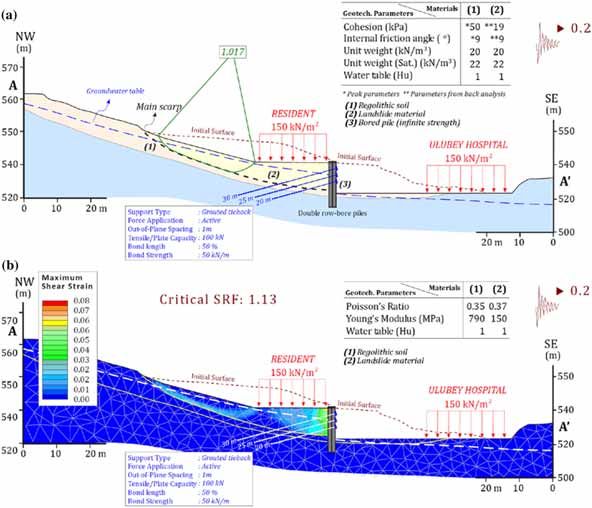
82       Page 2 of 12                                          J. Earth Syst. Sci. (2020)129 82

precipitation in Turkey (about 600 mm) was               instant Curries in the winter season. Thus, rainfall-
measured in 1 hr in the Hopa district and nearly         triggered landslides are frequently encountered
100 rainfall-induced landslide events were recorded      around Ulubey district. In addition, the natural
(Durmusß 2016). Over 50 deaths were reported only        topographic structure of the study area compli-
because of these three disasters. In another catas-      cates planned urbanization and the buildings are
trophic example, 170 mm of rainfall in 6 hrs was         often necessarily constructed on slopes. Highly
measured in 2016 and landslides caused many              weathered volcanic rocks are widely exposed in this
deaths in Ordu, which is another city in the north-      area; therefore, often slope stability problems occur
eastern part of Turkey. In addition to sudden and        especially in urban areas where slope design errors
very heavy rainfall, uncontrolled excavation is          also play a significant role. Thus, landslides are
another important triggering factor that causes          likely to occur in almost every uncontrolled exca-
landslides in the eastern Black Sea region. For          vation during construction activities in rainy sea-
example, the Cßatak landslide disaster (Trabzon          sons in the study area.
city) in 1988, which was caused by prolonged heavy          In this study, an Ulubey landslide (Bgure 2)
rainfall and incorrectly designed road cut applica-      triggered by an uncontrolled slope excavation
tion, caused 66 fatalities (Jones et al. 1989; Gencß     was investigated to determine the failure mech-
1993).                                                   anism and to design the appropriate retaining
   Ulubey (Ordu, NE Turkey) is a small and               structures for stabilization. For this purpose,
developing district in the north-eastern section of      seven investigation boreholes were drilled and a
Turkey (Bgure 1) with over 1500 mm of annual             seismic survey on a proBle was performed to
precipitation, and it is one of the highest precipi-     reveal vertical and horizontal continuity of the
tation areas in the region. It has steep peaks, spo-     undisturbed and landslide materials. In addition,
radic regolith soils covering the topography, and        standard     penetration      tests    (SPTs)    were

                                   Figure 1. Location map of the study area.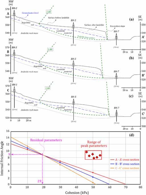
J. Earth Syst. Sci. (2020)129 82                                                         Page 3 of 12 82

                                   Figure 2. Field view of the Ulubey landslide.

performed in three boreholes to investigate the            3. Geotechnical investigations
variation of stiAness properties of the landslide
material in depth. Undisturbed and disturbed               The main objectives of the investigations and sur-
specimens were obtained, and laboratory experi-            veys that were performed on the site of potential
ments were performed to deBne the geotechnical             slope instability are collecting all the information
properties. Finally, to control the performance of         and data necessary for the stability analyses,
the recommended stabilization technique, the               assessing the risk of instability, and designing the
limit equilibrium (LE) and Bnite element method            remedial measures to relieve instability. For this
(FEM)-based two- and three-dimensional (2D                 purpose, seven boreholes were drilled (total length,
and 3D) numerical analyses were performed. The             151.5 m) to describe the geological model, to
obtained results were then compared.                       establish groundwater conditions (table 1), and to
                                                           obtain undisturbed samples for the laboratory
                                                           tests. Four boreholes were opened on the landslide
2. Geological setting                                      materials and three boreholes were drilled in the
                                                           upper elevations from the main scarp of the
Considering the structural differences and litho-          landslide.
logical properties, the eastern Pontide is described          According to borehole and site investigations,
                                               €
as a geological and tectonic unit in Turkey (Ozsa-         the thickness of soil material varies between 4.0
yar et al. 1981; Bektasß et al. 1995; Okay and             and 20.7 m, and the groundwater level is located at
Sßahint€
       urk 1997). The study area is situated on the        a depth of 1.0–4.0 m from the surface. The length of
west side of the eastern Pontide.                          the landslide, which occurred in residual soil with a
   In the study area, Late Cretaceous-aged for-            maximum thickness of 20 m, is approximately 130
mations are characterized by three different               m, while the width ranges between 80 and 110 m.
lithologies. The oldest unit, consisting of dacite,        Investigations on the site characterization indi-
rhyodacite, and pyroclastites, is conformably              cated that three different materials were deBned
overlain by claystone, siltstone, marl, and sand-          depending on the depth from borehole logs. These
stone. The youngest unit in the Late Cretaceous            materials are as follows: (1) sliding material (dis-
contains andesite, basalt, and pyroclastites.              turbed soil); (2) residual regolith (undisturbed
These units are cross-cut by the Middle Miocene-           soil); and (3) bedrocks consisting of andesite and
aged acidic rocks. The Plio-Quaternary-aged                trachyandesite.
regolith soil located in the study area includes              SPTs were performed on the landslide material
saprolite in the lower zone and soil material in           at 50-cm intervals in the BH-4, BH-5, and BH-6
the upper zone. The widely exposed 20–25-m                 boreholes to deBne the location of the failure sur-
thick reddish-brown regolith soil indicates deep           face. The SPT values with graphs are presented in
weathering of the bedrock surface. In the study            Bgure 4. It was concluded that the landslide did not
area, Cat areas are covered with residual regolith         occur between the bedrock and soil contact, and
and the studied landslide occurred in the upper            the failure surface was located 1–2 m above the
zone of the residual regolith that originated from         bedrock (Bgure 5). Furthermore, the seismic
Eocene–Miocene-aged        basic   volcanic    rocks       refraction survey on a proBle was performed to
(Bgure 3).                                                 obtain the dynamic elastic characteristics of the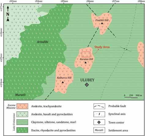
82        Page 4 of 12                                              J. Earth Syst. Sci. (2020)129 82

                      Figure 3. Geological map of the study area (modiBed from Temizel et al. 2012).

Table 1. Summary of the borehole data.

Borehole no.        Altitude (m)         Borehole depth (m)          Main rock depth (m)           Groundwater depth (m)
BH-1                    563.0                    24.0                         10.0                         4.00
BH-2                    562.0                    29.0                          8.3                         3.50
BH-3                    561.0                    22.0                          8.8                         3.00
BH-4                    546.0                    19.0                         15.0                         1.00
BH-5                    546.5                    21.0                         15.3                         2.00
BH-6                    546.5                    23.0                         15.2                         3.00
BH-7                    530.0                    13.5                          2.2                         4.00

geological materials. Using the outcomes of the               classiBed as the high plasticity clay (CH)
data obtained from all investigations and the Beld            (table 2). To determine the peak shear strength
observations, the engineering geological map with             parameters (cp and /p) of the residual regolith
the scale of 1/2500 and the cross-sections of the             (undisturbed soil), consolidated-undrained (CU)
landslide area were prepared according to IAEG                triaxial compression tests were performed. In
(1976) procedures (Bgure 5).                                  addition, the residual shear strength parameters
   The laboratory experiments were performed on               (cr and /r) were obtained from a back analysis
the undisturbed soil samples acquired from BH-1,              method using the three different geological cross-
BH-2, and BH-3 boreholes to determine the phy-                sections (Bgure 6). The locations of the shear
sico-mechanical properties (ASTM D422-69 2007;                surface in different cross-sections were determined
ASTM D4718 2015; ASTM D4318-17 2017a).                        by the evaluation of drilling logs and SPT results
Based on the UniBed Soil ClassiBcation System                 as well as the main scarp location. As seen from
(USCS) (ASTM 2487-06 2017b), all samples were                 table 3, the peak parameters were 50 kPa and 9°,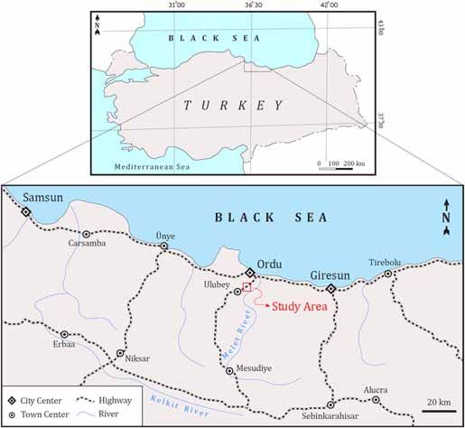
J. Earth Syst. Sci. (2020)129 82                                                        Page 5 of 12 82

                              Figure 4. Results of SPT conducted in some boreholes.

while residual strength parameters were 19 kPa            the density (kN/m3) and Vp, Vs are P-S wave
and 9°.                                                   velocities (m/s).
   To deBne the elastic properties of the undis-            The geophysical measurements show that P and
turbed soil and landslide material, the seismic           S wave velocities are 411 and 184 m/s for landslide
refraction method was applied using the Geomet-           material and 814 and 384 m/s for residual soil,
rics model 12-channel seismograph to obtain a             respectively. The dynamic Poisson’s ratio and the
proBle. The dynamic Poisson’s ratio (m) and               dynamic deformation modulus were calculated as
dynamic deformation modulus (E) were deter-               0.37 and 150 MPa for landslide materials and 0.35
mined based on the following equations that were          and 790 MPa for residual soil, respectively.
recommended by Tezcan et al. (2006) and the
elastic theory using the P and S-wave velocity
values (table 4).                                         4. Stability analysis
          h              i h               i
       m ¼ ðVP =VS Þ2  2 =2 ðVP =VS Þ2  1 ; ð1Þ         Because quantitative determination of the slope
                                                          stability is necessary for many engineering activi-
                                                      ties, the researchers have studied both rock and soil
         E ¼ l 3VP2  4Vs2 = VP2  Vs2 ;           ð2Þ
                                                          slope stability problems in the eastern Black Sea
                                                          region (e.g., Akg€un and Bulut 2007; Kesimal et al.
                  l ¼ qVs2 =100;                   ð3Þ
                                                          2008; Akg€  un 2011; Karaman et al. 2013; Alemdağ
                                                          et al. 2014; Gelisßli et al. 2015; Kaya et al.
                  q ¼ 0:44Vs0:25 ;                 ð4Þ
                                                          2016a, 2017; Kul Yahsßi and Ersoy 2018, Ersoy et al.
where m is Poisson’s ratio, E is the deformation          2019). Although several techniques are available
modulus (MPa), l is the shear modulus (MPa), q is         for slope analysis, based on the type of matter and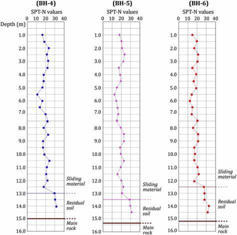
82         Page 6 of 12                                                   J. Earth Syst. Sci. (2020)129 82

             Figure 5. 1/2500 scaled engineering geological map and geological cross-section of the landslide area.

Table 2. The index properties of the different geological materials in the landslide area.

                                          Grain size distribution* (%)    Atterberg limits* (%)   Unit weight* (kN/m3)
Geological units         Thickness (m) Gravel       Sand    Silt + clay      LL              PI         cn       cs      USCS
Residual soil (1)      8.5–10.0              4        7         89            61             30     19.9        22.1     CH
Landslide material (2) [ 14.0                6        7         87            56             32     19.4        19.8     CH
*Average values, LL liquid limit, PL plastic limit, cn natural unit weight, cs saturated unit weight.

the characteristics of the landslide materials, LE                   be implemented after adequate investigation of site
analysis, and numerical analysis were chosen as the                  characterization and understanding of the causes of
most preferred stability methods in these studies.                   the landslide occurrence. If a slope has already
Landslide control and precaution techniques must                     moved, a control measure to stop the movement is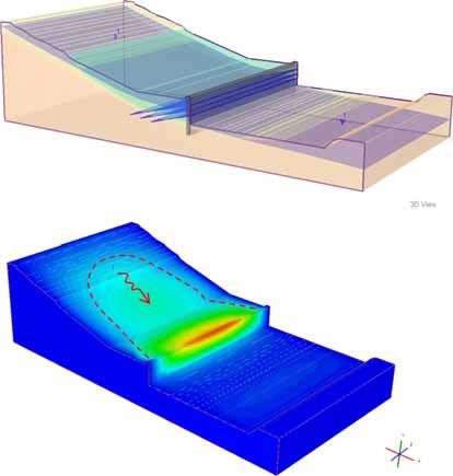
J. Earth Syst. Sci. (2020)129 82                                                                     Page 7 of 12 82

Figure 6. Back analysis carried out on three different geological cross-sections and the obtained residual parameters.

Table 3. Strength parameters of different geological materials of the landslide area.

                                                          Residual shear strength*                  Peak shear strength**
                                 Thickness
Geotechnical units                 (m)                  c (kPa)                 / (°)             c (kPa)                / (°)
Residual soil (1)                8.5–10.0                  –                      –                  50                   9
Landslide material (2)           [ 15.5                    19                     9                  –                    –
Main rock (3)                        –                InBnite strength
c, cohesion; /, internal friction angle.
*Obtained from back analysis on three different geological cross-sections.
**Obtained from consolidated-undrained triaxial compression tests.
82 Page 8 of 12 J. Earth Syst. Sci. (2020)129 82
Table 4. Average values of elastic parameters of the geological materials obtained from seismic wave
velocities.
Geotechnical units h (m) Vp (m/s) Vs (m/s) m E (MPa)
Residual soil (1) 8.5–10.0 814 384 0.35 790
Landslide material (2) [15.5 411 184 0.37 150
h, thickness; Vp, P-wave velocity; Vs, S-wave velocity; m, Poisson’s ratio; E, deformation modulus.
required to counteract the processes that started method. In the FEM–SSR method, the FOS is
the slide. represented by the Strength Reduction Factor
In this study, the stability of Ulubey landslide (SRF). The SSR technique includes systematic use
was evaluated using different analysis techniques. of FEM to deBne a SRF value that transports a
The 2D-LE analysis was performed using Slide v9.0 slope to the limit of failure. The shear strength
(Rocscience Inc. 2017) software to calculate the parameters are scaled until the stability limit is
factor of safety (FOS) for the failed slope after the reached. The SRF value is the ratio between the
application of support. In addition to 2D-LE actual and the model strength at the stability limit.
analysis, the FEM-based 2D and 3D numerical One of the beneBts of the SSR method is that there
analyses were used with the RS2 v9.0 (Rocscience is no requirement for the principal estimate at the
Inc. 2016a) and RS3 v1.0 (Rocscience Inc. 2016b) description of the critical failure surface. However,
softwares. In the analysis models, the soil and the FOS value could not be calculated in the 3D
landslide materials were identiBed using table 2 analyzed model because v1.0 of the RS3 program
and the bedrock was deBned as the inBnite strength does not have a SSR option. Therefore, the results
material. of the 2D-FEM and 3D-FEM models are compared
Slide is a PC program that is constantly used for based on the location of the stress concentration
the computation of FOS for soil slopes considering and total displacement outcome (Kaya et al.
the LE approach. The different geometrical sur- 2016b, 2018).
faces with different lithology can be demonstrated To control the long-term performance of the
in both humble and multipart form using Slide. suggested support design under dynamic condi-
This program also permits the users to delineate tions, the horizontal seismic coefBcient (k) of 0.22 g
and examine groundwater matter using a similar was applied to the model. The k value was calcu-
model as for the slope stability matter. In the LE lated using the following formula recommended by
method, which accounts for a significant portion of Towhata (2008) for pseudo-static analysis. In this
the slope stability analysis approaches, the equation, the peak horizontal ground acceleration
Mohr–Coulomb failure criterion is grounded, a (PHA) was chosen as 0.25 g for the study area
surface having a slide probability risk is selected, based on the iso-acceleration map prepared by
and the stress situation that would be the basis for Erdik et al. (2006), which took into account the
the failure along this surface is examined. Then, active faults in Turkey.
the shear stress that saves and steadies the mass in
the shear zone is determined. The considered stress
k ¼ PGA0:333 =3; ð5Þ
values are compared, and FOS is then calculated
(Alemdağ et al. 2015; Kaya 2017). where k is the horizontal seismic coefBcient (for
RS2 is an inCuential and supple program in PGA [ 0.2 g) and PGA is the peak ground accel-
which the Shear Strength Reduction (SSR) tech- eration value.
nique is joined into the FEM and clariBcation In common Beld applications, such as retaining
modules. Because of the fast developments in walls, drainage, geogrids in embankments, Catten-
computer science, the FEM–SSR (Bnite element ing, buttressing, anchors, and vegetation, are the
method–shear strength reduction) method-based most preferred landslide remediation methods.
programs are being used more frequently than in However, in this study, double row-bore piles (/,
the past. In the FEM–SSR technique, the elastic 100 cm) that was supported with grouted tieback
parameters and forces acting on the slope-forming were chosen as the most realistic support design for
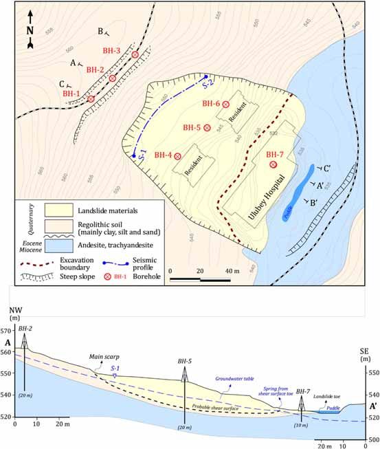
material are considered to be dissimilar to the LE the landslide because there is an inadequate areaJ. Earth Syst. Sci. (2020)129 82 Page 9 of 12 82 for slope Cattening. The characteristics of the FEM-based 2D numerical analysis. In the analysis applied support elements are given in Bgure 7. The model, the ground surface was assumed to be a free dynamic long-term eDciency of the supported boundary. However, the bottom and vertical slope was controlled in three steps. boundaries of the model were closed to prevent In the Brst step, the 2D-LE analysis was per- displacements. In the mesh, 500 six-nodded trian- formed taking into account the earthquake and gular Bnite elements were used. Gravitational building loads. The groundwater condition was loading was applied in the numerical solutions. In deBned using the data obtained from borehole this method, the Mohr–Coulomb failure criterion investigations and the auto water table (Hu) option was taken into account, as in the applied 2D-LE was used (table 1). The Mohr–Coulomb failure analysis method. According to the 2D-FEM anal- criterion (Mohr 1900) was applied, and the Janbu ysis, the FOS value was determined to be 1.13 for Method (Janbu 1973) was chosen for the combined the dynamic long-term stability (Bgure 7b). slide-type analyses. The landslide material was For the slope stability under an earthquake characterized using the residual strengths that eAect, a FOS value of 1.0–1.1 is necessary. In this were obtained from the back analysis. However, study, a safety factor of 1.0 (LE condition) was the undisturbed zone was identiBed using the peak taken into account, and it was useful for dynamic strengths that were obtained from laboratory long-term stability (TGDH 2013). Therefore, it studies. According to the 2D-LE analysis, the FOS was concluded that the results acquired from the values were determined as 1.017 for the dynamic 2D-LE and 2D-FEM analyses are acceptable, and long-term stability condition (Bgure 7a). the reinforcement suggestions provided convincing In the second step, the eDciency of the suggested outcomes. Furthermore, Bgures 7(a and b) show remediation planning was controlled using the that the location of the critical failure surface Figure 7. LE (a) and 2D-FEM–SSR (b) analyses evaluated for pseudo-static condition along the A–A0 cross-section.
82       Page 10 of 12                                              J. Earth Syst. Sci. (2020)129 82
                 (a)

                                                                                           Solids: Total
                 (b)                                                                       Displacement
                                                                                           min (all):    0 m
                                                                                           min (stage): 0 m
                                                                                                  0.00000
                                                                                                  0.00275
                                                                                                  0.00550
                                                                                                  0.00825
                                                                                                  0.01100
                                                                                                  0.01375
                                                                                                  0.01650
                                                                                                  0.01925
                                                                                                  0.02200
                                                                                                  0.02475
                                                                                                  0.02750
                                                                                           max (stage):0.0255233 m
                                                                                           max (all):0.0255233 m

                       Figure 8. 3D-FEM–SSR analysis result evaluated for pseudo-static condition.

completely coincides with the results of the 2D-LE            exposed to excessive rainfall after uncontrolled
and 2D-FEM analyses.                                          excavation during construction of a hospital in
   In the third step, to check the 2D-LE and 2D-FEM           Ulubey (Ordu city, NE Turkey) was investigated.
stability analyses outcomes, the 3D-FEM model was                To deBne the geotechnical characteristics of the
used. The thickness of the model was chosen 80 m,             study area, seven boreholes were drilled, seismic
which was the same as the actual excavation width             reCection measurement on a proBle was conducted,
that was applied in the Beld. Because there were no           and standard penetration tests were performed. In
unevenness differences that would aAect the 3D                addition, undisturbed specimens were collected
analysis results, the same surface topography was             from the boreholes to deBne the index and strength
used as in the 2D model. The location of the stress           characteristics. The peak shear strength parame-
concentrations obtained from the 3D model showed a            ters of the residual soils were determined from
close agreement with the 2D analysis results                  consolidated–undrained       triaxial    compression
(Bgure 8). However, the total displacement values             experiments. However, the residual shear strength
showed that the 3D model leads to a more conserva-            parameters of the landslide material were deter-
tive result than the 2D model. While the total dis-           mined using the back analysis technique on differ-
placement value obtained from 2D-FEM was 8.24 cm,
                                                              ent geological cross-sections.
the total displacement value for 3D-FEM model was
                                                                 The following three different geotechnical units
2.55 cm.
                                                              were identiBed as a result of the site investigations
                                                              and laboratory tests: (1) sliding materials (failed or
5. Conclusions                                                disturbed soil); (2) residual regolith (undisturbed
                                                              soil); and (3) bedrocks (basic volcanic rocks).
The main reasons of almost all landslides in NE               According to the SPT results, the failure surface
Turkey are uncontrolled excavations and heavy                 was 1–2 m above the bedrock. A double row-bore
rainfalls. In this study, the remediation design for          piles (/, 100 cm) supported with grouted tieback
landslides that occurred on a slope that was                  was chosen as the safest and most economical
J. Earth Syst. Sci. (2020)129 82 Page 11 of 12 82
support design for the landslide for long-term sta- Environ. 58 95–98, https://doi.org/10.1007/s10064005
bility. To control the eDciency of the suggested 0002.
Durmusß O 2016 Investigation of the dynamic cloud structures
support design under dynamic conditions, 2D and
and meteorological analysis of heavy rain event that caused
3D slope stability analyses were performed. This Cash Cood in Hopa on August 24, 2015; Disertation,
study showed that LE and FEM-based softwares _
Istanbul Technical University, 105p.
are easy and advantageous simulation instruments Erdik M, Sßesßetyan K, Demircioğlu M and Durukal E 2006
to determine the landside characteristics. Ulasßtırma Bakanlığı Demiryolları, Limanlar ve Hava Mey-
_ ßaatı Genel Mud
danları Ins € url
€ uğ
€ u€ kıyı yapıları, demiryolları
ve hava meydanları insßaatları deprem teknik y€ onetmeliği
Acknowledgements icßin deprem tehlikesi belirlemesi, BU € Kandilli Rasathanesi
ve Deprem Arasßtırma Enstitus € u€ (in Turkish).
Ersoy H, Karahan M, Gelisßli K, Akgun € A, Anilan T and
Authors would like to express their sincere grati-
€
Sunnetci M O et al. 2019 Modelling of the landslide-induced
tude to the editor and reviewers. impulse waves in the Artvin Dam reservoir by empirical
approach and 3D numerical simulation; J. Manage Eng. 249
112–128, https://doi.org/10.1016/j.enggeo.2018.12.025.
Genc S 1993 Structural and geomorphological aspects of the
References Catak landslide, NE Turkey; Q. J. Eng. Geol. Hydrogeol.
26(2) 99–108.
Alemdağ S, Akgun A, Kaya A and G€ okceoğlu C 2014 A large Gelisßli K, Kaya T and Babacan A E 2015 Assessing the factor
and rapid planar failure causes mechanism and conse- of safety using an artiBcial neural network: Case studies on
quences Mordut Gumushane Turkey; Arab. J. Geosci. 3 landslides in Giresun, Turkey; Environ. Earth Sci. 73(12)
1205–1221, https://doi.org/10.1007/s12517-012-0821-1. 8639–8646, https://doi.org/10.1007/s12665-015-4027-1.
Alemdag S, Kaya A, Karadag M, Gurocak Z and Bulut F 2015 IAEG 1976 Engineering Geological Map: A Guide to Their
Utilization of the limit equilibrium and Bnite element Preparation. International Association of Engineering
methods for the stability analysis of the slope debris: An Geology, UNESCO Press, Paris, 79p.
example of the Kalebasi district (NE Turkey); J. Afr. Earth Janbu N 1973 In: Slope Stability Computations in Embank-
Sci. 106 134–146, https://doi.org/10.1016/j.jafrearsci. ment-Dam Engineering (eds) Hirschfeld R C and Poulos S
2015.03.010. J, Wiley, New York, pp. 47–86.
€ A and Bulut F 2007 Gis-based landslide susceptibility
Akgun Jones D K C, Lee E D, Hearn G and Gencß S 1989 The Cßatak
for Arsin-Yomra (Trabzon, North Turkey) Region. Envi- landslide disaster, Trabzon Province, Turkey; Terra Nova
ron. Geol. 51(8) 1377–1387, https://doi.org/10.1007/ 1(1) 84–90, https://doi.org/10.1111/j.1365-3121.1989.
s00254-006-0435-6. tb00331.x.
€ A, Dağ S and Bulut F 2008 Landslide susceptibility
Akgun Kaya A, Alemdağ S, Dağ S and Gurocak € Z 2016a Stability
mapping for a landslide-prone area (Findikli, Ne of Turkey) assessment of high-steep cut slope debris on a landslide
by likelihood-frequency ratio and weighted linear combina- (Gumushane, NE Turkey); Bull. Eng. Geol. Environ. 75
tion models; Environ. Geol. 54 1127–1143, https://doi.org/ 89–99, https://doi.org/10.1007/s10064-015-0753-6
10.1007/s00254-007-0882-8. Kaya A, Akgun € A, Karaman K and Bulut F 2016b Under-
€ A 2011 Assessment of possible damaged areas due to
Akgun standing the mechanism of a slope failure on nearby a
landslide-induced waves at a constructed reservoir using highway tunnel route by different slope stability analysis
empirical approaches: Kurtun (North Turkey) Dam reser- methods: A case from NE Turkey; Bull. Eng Geol Environ.
voir area; Nat. Hazards Earth Sys. 11 1341–1350, https:// 3(75) 945–958, https://doi.org/10.1007/s10064-015-0770-
doi.org/10.5194/nhess-11-1341-2011. 5.
ASTM 2007 Standard Test Method for Particle-Size Analysis Kaya A 2017 Geotechnical assessment of a slope stability
of Soils. ASTM D422-69, West Conshohocken, PA. problem in the Citlakkale residential area (Giresun, NE
ASTM 2015 Standard Practice for Correction of Unit Weight Turkey); Bull. Eng. Geol. Environ. 3(76) 875–889, https://
and Water Content for Soils Containing Oversize Particles. doi.org/10.1007/s10064-016-0896-0.
ASTM D4718/D4718M, West Conshohocken, PA. Kaya A, Karaman K and Bulut F 2017 Geotechnical inves-
ASTM 2017a Standard Test Methods for Liquid Limit, Plastic tigations and remediation design for failure of tunnel portal
Limit, and Plasticity Index of Soils. ASTM D4318-17, West section: A case study in northern Turkey; J. Mt. Sci.-Engl.
Conshohocken, PA. 14(6) 1140–1160, https://doi.org/10.1007/s11629-016-
ASTM 2017b Standard Practice for ClassiBcation of Soils for 4267-x.
Engineering Purposes (UniBed Soil ClassiBcation System). Kaya A, Bulut F and Dağ S 2018 Bearing capacity and slope
ASTM 2487-06, West Conshohocken, PA. stability assessment of rock masses at the Subasi Viaduct
Bektasß O, Yılmaz C, Taslı K, Akdağ K and Ozg € ur
€ S 1995 Site, NE Turkey; Arab. J. Geosci. 11 1–17, https://doi.
Cretaceous rifting of the eastern Pontide carbonate plat- org/10.1007/s12517-018-3477-7.
form (NE Turkey): The formation of carbonates breccias Kul Yahsßi B and Ersoy H 2018 Site characterization and
and turbidites as evidences of a drowned platform; Geolo- evaluation of the stability of the Yesilyurt Landslide
gia. 57(1–2) 233–244. (Trabzon, NE Turkey) using back analysis method; J.
Bulut F, Boynukalın S, Tarhan F and Ataoglu E 2000 Geophys. Eng. 15(3) 927–937, https://doi.org/10.1088/
Reliability of landslide ısopleth maps; Bull. Eng. Geol. 1742-2140/aaa9c3.82 Page 12 of 12 J. Earth Syst. Sci. (2020)129 82 Karaman K, Ercßıkdı B and Kesimal A 2013 The assessment of Rocscience Inc. 2016b RocData v5.0 rock, soil and disconti- slope stability and rock excavatability in a limestone nuity strength analysis. Toronto, Ontario, Canada, www. quarry; Earth Sci. Res. J. 17(2) 169–181. rocscience.com. Kesimal A, Ercikdi B and Cihangir F 2008 Environmental Rocscience Inc. 2017 RS2 v9.0 Bnite element analysis for impacts of blast-induced acceleration on slope instability at excavations and slopes. Toronto, Ontario, Canada, www. a limestone quarry; Environ. Geol. 54(2) 381–389, https:// rocscience.com. doi.org/10.1007/s00254-007-0825-4. Temizel I,_ Arslan M, Gilles R and Jacques P J 2012 Mohr O 1900 Welche Umst€ ande bedingen die elastizit€ ats- Petrochemistry geochronology and Sr–Nd isotopic system- grenze und den bruch eines materials? Zeit. Des. Ver. Deut. atics of the Tertiary collisional and post collisional volcanic Ing. 44 1524–1530. rocks from the Ulubey Ordu area eastern Pontide NE Okay A I and Sßahinturk€ O € 1997 Geology of the eastern Turkey Implications for extension related origin and mantle Pontides; In: Regional and Petroleum Geology of the Black source characteristics; Lithos. 128–131 126–147, https:// Sea and Surrounding Region (ed.) Robinson A G, Am. doi.org/10.1016/j.lithos.2011.10.006. Assoc. Petrol. Geol. Memoir 68 291–311. Tezcan S S, Ozdemir Z and Keceli A 2006 Allowable bearing € Ozsayar T, Pelin S and Gedikoğlu A 1981 Doğu Pontidler’de capacity of shallow foundations based on shear wave Kretase (Cretaceous in Eastern Pontides). Karadeniz velocity; Geotech. Geol. Eng. 24(1) 203–218, https://doi. Technical University Faculty of Earth science Publications; org/10.1007/s.10706-004-1748-4. Jeoloji 1 65–114 (in Turkish with English abstract). TGDH 2013 SpeciBcation for Highway Works (in Turkish). Rocscience Inc. 2016a Dips v7.0 graphical and statistical Turkish General Directorate of Highways, Ankara, Turkey. analysis of orientation data. Toronto, Ontario, Canada, Towhata I 2008 Geotechnical earthquake engineering. www.rocscience.com. Springer Science & Bussines Media, Heidelberg. Corresponding editor: ARKOPROVO BISWAS
You can also read