A Low-Cost, Point-of-Care Test for Confirmation of Nasogastric Tube Placement via Magnetic Field Tracking - MDPI
←
→
Page content transcription
If your browser does not render page correctly, please read the page content below
sensors
Article
A Low-Cost, Point-of-Care Test for Confirmation of Nasogastric
Tube Placement via Magnetic Field Tracking
Muneaki Miyasaka 1, * , Hao Li 2 , Kon Voi Tay 3 and Soo Jay Phee 1

                                          1   School of Mechanical and Aerospace Engineering, Nanyang Technological University,
                                              Singapore 639798, Singapore; msjphee@ntu.edu.sg
                                          2   Department of Otorhinolaryngology, Tan Tock Seng Hospital, Singapore 308433, Singapore;
                                              li_hao@ttsh.com.sg
                                          3   Department of General Surgery, Woodlands Health Campus, Singapore 069112, Singapore;
                                              kon_voi_tay@whc.sg
                                          *   Correspondence: mmiyasaka@ntu.edu.sg

                                          Abstract: In this work, we aim to achieve low-cost real-time tracking for nasogastric tube (NGT)
                                          insertion by using a tracking method based on two magnetic sensors. Currently, some electromagnetic
                                          (EM) tracking systems used to detect the misinsertion of the NGT are commercially available. While
                                          the EM tracking systems can be advantageous over the other conventional methods to confirm the
                                          NGT position, their high costs are a factor hindering such systems from wider acceptance in the
                                          clinical community. In our approach, a pair of magnetic sensors are used to estimate the location of a
                                          permanent magnet embedded at the tip of the NGT. As the cost of the magnet and magnetic sensors
                                          is low, the total cost of the system can be less than one-tenth of that of the EM tracking systems. The

                                   experimental results exhibited that tracking can be achieved with a root mean square error (RMSE)
                                          of 2–5 mm and indicated a great potential for use as a point-of-care test for NGT insertion, to avoid
Citation: Miyasaka, M.; Li, H.; Tay,
                                          misplacement into the lung and ensure correct placement in the stomach.
K.V.; Phee, S.J. A Low-Cost,
Point-of-Care Test for Confirmation of
Nasogastric Tube Placement via
                                          Keywords: magnetic sensors; wearable sensors; real-time systems
Magnetic Field Tracking. Sensors 2021,
21, 4491. https://doi.org/10.3390/
s21134491
                                          1. Introduction
Academic Editors: Yasushi Takemura              The nasogastric tube (NGT) is a flexible rubber or plastic tube which is used for medical
and Takashi Yoshida                       purposes such as treatment of ileus or bowel obstruction, stomach lavage, administration of
                                          medications, and delivery of nutrients [1]. The NGT is manually inserted through the nose
Received: 31 May 2021
                                          into the stomach often without direct visualization of the location of its tip. Because the tube
Accepted: 28 June 2021
                                          tip location is unknown, misplacement of the tube is relatively common and it can cause
Published: 30 June 2021
                                          fatal complications [1–3]. For instance, there is some possibility of the NGT entering the
                                          trachea and the lung instead of the esophagus, resulting in pneumothorax or pneumonia
Publisher’s Note: MDPI stays neutral
                                          which could be fatal [4].
with regard to jurisdictional claims in
                                                The pH test is one bedside method to assess the NGT position. The procedure involves
published maps and institutional affil-
                                          aspiration of fluid from the tube and the tube is considered inside the stomach if a pH
iations.
                                          of 1–5.5 is obtained [5]. However, a misleading pH can be recorded for the patients with
                                          hiatus hernia and gastro-oesophageal reflux [4]. Patients taking proton pump inhibitors or
                                          requiring continuous enteral feeds could have unexpected pH results [6]. Using an X-ray is
                                          an accurate method to confirm the NGT position since the whole length of the tube can be
Copyright: © 2021 by the authors.
                                          visualized. However, it is reported that misinterpretation of X-rays is the main causal factor
Licensee MDPI, Basel, Switzerland.
                                          of adverse events [5]. The X-ray confirmed tube location is only true at the time the X-ray
This article is an open access article
                                          is taken. If patients have symptoms such as coughing, retching, or vomiting, the X-ray may
distributed under the terms and
                                          need to be repeated and there is a small increase of carcinogenic risk. Besides, subsequent
conditions of the Creative Commons
Attribution (CC BY) license (https://
                                          clinical procedures are then delayed due to the extra time incurred for patient transfer to
creativecommons.org/licenses/by/
                                          the radiology room and for procedures of taking and interpreting X-rays. The delay can
4.0/).
                                          take away time crucial for feeding, hydration, and medication [4]. Most importantly, both

Sensors 2021, 21, 4491. https://doi.org/10.3390/s21134491                                                  https://www.mdpi.com/journal/sensors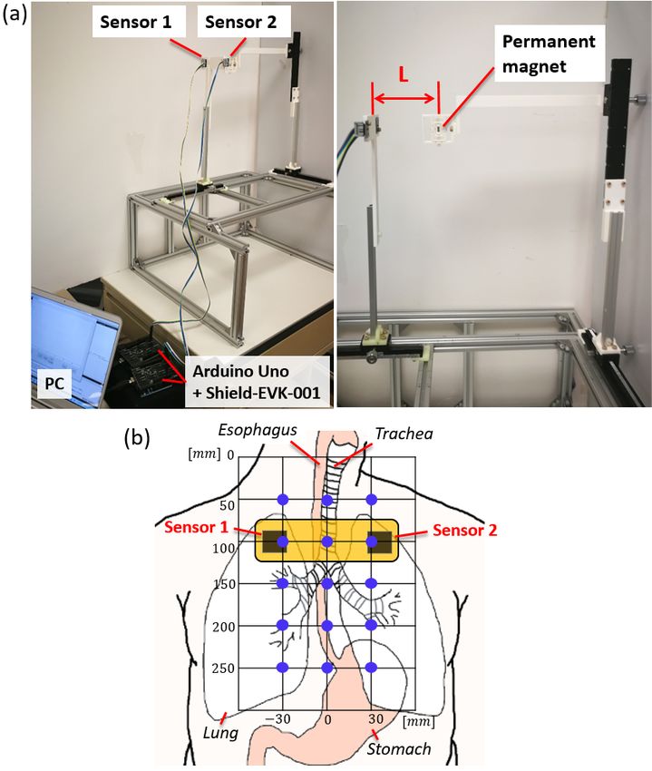
Sensors 2021, 21, 4491                                                                                            2 of 17

                         pH tests and X-ray are only performed post tube insertion. Therefore, harm caused in the
                         midst of the insertion cannot be detected/avoided.
                               In contrast, electromagnetic (EM) tracking systems, or specifically, electromagnetic
                         sensor guided enteral access systems (EMS-EAS), are able to provide real-time 3D (the
                         anterior and cross-sectional) path of the NGT during the insertion process. Studies showed
                         that 98% of the tube position from EMS-EAS and X-ray corresponded and the remaining 2%
                         can be considered to be caused by the relocation of the tube between EMS-EAS and X-ray,
                         misuse of EMS-EAS system, and misinterpretation of the X-ray [2,7]. Thus, EM tracking
                         can realize a safer and more reliable insertion process and can potentially replace X-ray to
                         reduce the risk of complication, time to next clinical procedure, and cost [8]. However, EM
                         tracking systems are still expensive. For example, CORTRAK EMS-EAS (Avanos Medical,
                         USA) costs £12,000 [9]. The system requires a dedicated single-patient-use tube with a
                         wired sensor head and therefore, the cost for each use is not low.
                               Passive magnet tracking is another feasible method of NGT tracking. While the
                         EM tracking systems require an active magnetic field generator (external system) and
                         magnetic field receiver (tracking object), the passive magnet tracking system employs
                         external magnetic sensors and a permanent magnet as a tracking target. Various passive
                         magnet tracking methods have been investigated especially in the field of endoscope
                         capsule tracking [10–14]. However, the size of the permanent magnet used for the tracking
                         is usually large and not suitable for NGT insertion. Sun et al. developed a wearable sensor
                         system around the neck to track a permanent magnet embedded at the tip of the NGT [15].
                         The tube placement is suspected to be incorrect if the sagittal axis position deviates from
                         the expected path because there are distinct position differences between the paths to the
                         esophagus and to the trachea/bronchi. The insertion is considered erroneous if the frontal
                         plane position shifts sideways since the trachea splits laterally into the two primary bronchi.
                         Although the system has a root mean square error (RMSE) of less than 5.3 mm, the accuracy
                         was only verified from −70 to 50 mm from the sensors along the longitudinal axis and the
                         accuracy decreases as the target goes further away from the sensors. Since the average
                         length of the trachea is roughly 100 mm, the tracking up to the bronchi could be difficult
                         to achieve considering anatomical variations [16]. The tracking speed achieved by their
                         system is 10 Hz.
                               We have previously developed a passive magnet tracking method based on two
                         magnetic sensors, for tracking the magnetically inflatable intragastric balloon capsule
                         (MIBC) [17]. The system uses two three-axis magnetic sensors placed in front and back
                         of the patient. By using the grid search method, the algorithm estimates the position
                         of the magnet embedded in the capsule by searching the sensed magnetic field from a
                         table with a pre-calculated magnetic field. To improve the tracking stability and accuracy,
                         the search range was actively adjusted based on the anatomy of the esophagus and the
                         search threshold was modulated. We demonstrated that the proposed method was able to
                         track the position of the MIBC along the esophagus with a 3.5 mm mean absolute error.
                         However, it could only provide sagittal plane tracking. To detect the deviation of the NGT
                         position toward the lung, frontal plane tracking is required. In addition, for the NGT
                         application, as the magnet size is limited by the NGT size that is smaller than the MIBC
                         size, the tracking becomes more challenging. Therefore, the system from our previous
                         work is not suitable for NGT tracking.
                               In this work, we aim to achieve inexpensive real-time tracking of NGT insertion,
                         point of care test NGT insertion by implementing a two-sensor-based magnetic tracking
                         method. By introducing the new sensor orientation and modifying the tracking algorithm,
                         we track the frontal plane position of the NGT with a permanent magnet embedded at
                         the tip. By providing real-time visual information of the tip’s position, the user can avoid
                         erroneous insertion of the NGT into the lung and hence, the risks associated with NGT
                         insertion can be reduced. Compared to the EM tracking systems, our approach may not
                         be able to achieve as accurate or as large range tracking due to the nature of the passive
                         magnet tracking method. However, the accuracy and tracking range can be adequate for
Sensors 2021, 21, 4491                                                                                           3 of 17

                         the NGT tracking application. Since only two sensors are required for tracking, the cost and
                         complexity of the setup is minimal. Additionally, our approach is beneficial because it does
                         not require wiring for the tracking object (permanent magnet). This paper is organized
                         as follows. Section 2 presents the setup of our two-sensor-based tracking system, details
                         of the tracking algorithm, and experimental setup to evaluate our approach. Section 3
                         presents the results of the experiments followed by the discussion in Section 4. Section 5
                         provides conclusion and future work.

                         2. Materials and Methods
                         2.1. Two-Sensor Setup
                              An overview of the two-sensor setup is shown in Figure 1. In this work, we employed
                         two three-axis magnetic sensors with 0.042 µT detectivity (BM1422AGM, ROHM, Japan).
                         The sampling frequency was set at 100 Hz. We used the initial setting of the sensor from the
                         manufacturer and no calibration is carried out. The sensors are placed in front of the patient
                         on the frontal plane with 80 mm separation along the frontal axis without longitudinal
                         offset. Each magnetic sensor is connected to a sensor shield (SHIELD-EVK-001, ROHM,
                         Japan) which is interfaced with an Arduino UNO board (Arduino, Ivrea, Italy). As for the
                         tracking target, a grade N52 neodymium axially-magnetized cylindrical permanent magnet
                         of dimensions  3.18 mm × 9.53 mm (K&J Magnetics, Miami, FL, USA) was embedded
                         at the distal tip of the NGT. The size of the magnet is small enough to fit inside the 14
                         French gauge (FG) (4.67 mm) or larger NGTs. The tracking algorithm is written in C++
                         and executed on a laptop PC with the Intel i7-7500U (2 core, 4 thread, and 2.7 GHz) CPU
                         and 16GB RAM. The actual setup can be seen in Section 2.3. The total cost of the system
                         including the PC was about 1000 USD.

                         Figure 1. Overview of the two-sensor-based magnetic NGT tracking system.

                              Figure 2 shows the anatomy of the digestive and respiratory pathways. The average
                         length of the esophagus (from the cervical esophagus to the EG junction cardia) for an
                         adult is 250 mm [18]. The trachea is 100 mm long on average and it passes vertically down
                         the midline of the chest in healthy subjects and bifurcates at the level of the 4th to 5th
                         thoracic vertebrae [16,19]. This bifurcation is marked by the carina and it corresponds
                         to the palpable landmark of the angle of Louis on the sternum [20]. Left and right main
                         bronchi emerge from the carina. The right the main bronchus is more vertical than the left,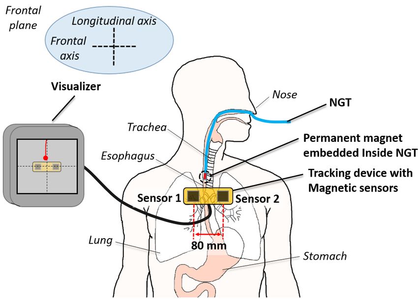
Sensors 2021, 21, 4491                                                                                          4 of 17

                         making an average angle of 35 (± standard deviation (SD) of 8) degrees with respect to
                         the trachea in a recent study of 2107 Chinese adult patients [21]. The left main bronchus
                         is typically 10 to 15 degrees more horizontal than the right [22]. Both main bronchi
                         further divide into lobar bronchi, and the lobar bronchi divide into segmental bronchi.
                         The luminal diameter of the bronchi decreases as they divide. Because the diameter of
                         a size 14 FG NGT, the typical size used in adult patients, is 4.67 mm, it should likely
                         terminate in a lobar or a segmental bronchus of the right lower lobe [23,24]. Therefore, we
                         are interested in the distance from the carina to the segmental bronchi of the right lower
                         lobe, which is at least 40 mm [19,22] (the sum of the length of the right main bronchus
                         and the bronchus intermedius). Beyond the bronchus intermedius, the length and the
                         diameter of the airways become difficult to predict. Likewise, if the NGT is inserted into
                         the left lung, it will probably pass through the left main bronchus into the left lower lobar
                         bronchus [23,24]. That is a distance of at least 45 mm beyond the carina, the length of the
                         left main bronchus [19,22].
                               The tracking range covered by the system was ±150 mm in the longitudinal direction
                         from the center of the sensors. Therefore, the esophagus and the airway where the NGT
                         can enter can be covered. In terms of the tracking depth or the tracking in the sagittal
                         axis direction, the sensors can cover up to 100 mm. Since the mean diameter of the
                         anterior–posterior rib cage ranges from 80 to 100 mm, the region of interest is within the
                         tracking range [25].

                         Figure 2. Dimensions of the esophagus and airway where the NGT can enter.

                              In the study by Sun et al, the sagittal plane position of the tube below the neck
                         was monitored to differentiate the insertion into the esophagus and trachea/bronchi [15].
                         However, since there is no reference of where the esophagus or trachea is, it is not always
                         easy to judge misinsertion based on the sagittal plane tracking information. For our
                         approach, since the tracking range is larger, we can focus on the frontal deviation of the
                         NGT position around the chest area to detect incorrect insertion. In addition, our method
                         can confirm whether the NGT passes the esophagogastric junction to the stomach which is
                         beneficial before using the NGT.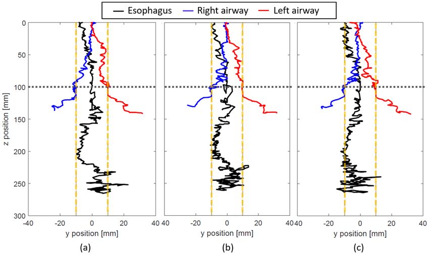
Sensors 2021, 21, 4491 5 of 17
2.2. Tracking Algorithm
For simplicity, we define the sagittal, frontal, and longitudinal axis as x, y, and z
respectively. The algorithm uses the grid search to find the sensor obtained magnetic
field from an array of the model-based pre-calculated magnetic field and estimate the
position and orientation of the target magnet. The grid search was performed for each of
the two sensors individually. In order to isolate the magnetic field of the target magnet
from background fields, the magnetic field of the surrounding environment is measured
and offset from the sensor value. The sensor-obtained vector after offsetting is denoted as:
Bsensor j ,x
Bsensor j = Bsensor j ,y (1)
Bsensor j ,z
where the subscript j(= 1, 2) indicates sensor 1 and sensor 2, respectively and the subscripts
x, y, and z indicate the components of the magnetic field vector. Since the magnet has
a cylindrical shape, all the positions and orientations can be represented with the five
variables (x, y, and z Cartesian coordinates and θ pitch and θroll rotation angles). Therefore,
the model-based pre-calculated magnetic field is a function of those five variables and
denoted as:
Bmodel,x ( x, y, z, θ p , θr )
Bmodel ( x, y, z, θ p , θr ) = Bmodel,y ( x, y, z, θ p , θr ) (2)
Bmodel,z ( x, y, z, θ p , θr )
However, it is difficult to find the exact same vector due to uncertain factors such as
sensor misalignment and noise. To take these uncertainties into account, a search threshold
vector Bthresh j = [ Bthresh j ,x , Bthresh j ,y , Bthresh j ,z ] T is introduced. All the sets of the magnet
position and orientation that satisfy the below condition are considered as the solutions of
the grid search:
| Bmodel ( x, y, z, θ p , θr ) − Bsensor j | ≤ | Bthresh j | (3)
The array of the found sets from the grid search is denoted Pj . Since we have two
sensors, two arrays that contain the possible solutions (P1 and P2 ) are obtained. The possible
solution sets are further narrowed down by extracting the overlapped sets:
Poverlap12 =
x̂1 ŷ1 ẑ1
θ̂ p,1 θ̂r,1
x̂2 ŷ2 ẑ2 θ̂ p,2 θ̂r,2
P1 ∩ P2 = . .. , (4)
.. .. ..
.. . . . .
x̂ N12 ŷ N12 ẑ N12 θ̂ p,N12 θ̂r,N12
where Poverlap12 indicates the overlapped sets for sensor 1 and sensor 2. N12 is the number
of the overlapped sets from sensor 1 and sensor 2. Here, we also consider the sensor align-
ment and noise uncertainties, and the sets from two sensors are considered as overlapped if
the difference of all the components are within an overlap threshold. The overlap threshold
for sensors 1 and 2 is denoted Pthresh12 . The final position-tracking result in the frontal
plane (yest and zest ) is obtained by taking the average as follows:
N12 N12
∑ ŷi ∑ ẑi
i =1 i =1
yest = , zest = . (5)
N12 N12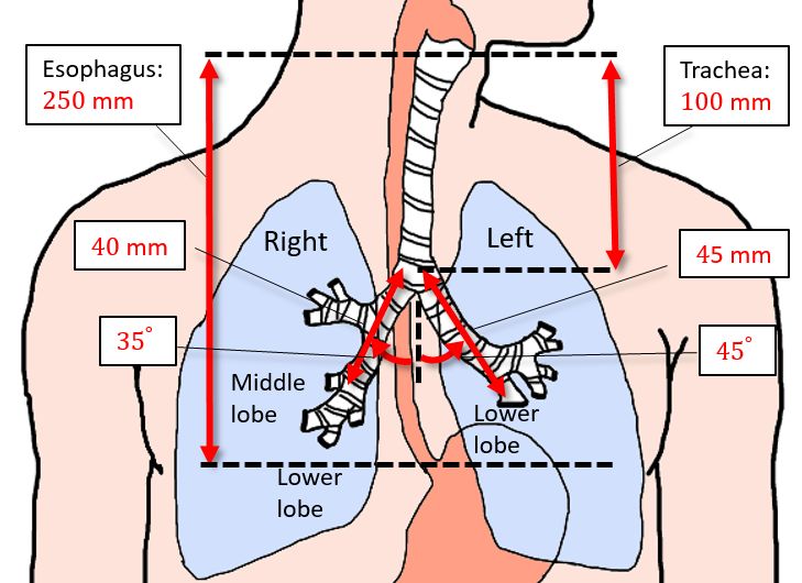
Sensors 2021, 21, 4491                                                                                                 6 of 17

                         2.2.1. Precalculation of Magnetic Field
                               The precalculated magnetic field Bmodel ( x, y, z, θ p , θr ) needs to be as accurate as possi-
                         ble to achieve the best localization result. Since the magnetization of the magnet may not
                         exactly match the specification, it is ideal to measure the field around the actual magnet
                         employed rather than using a model. However, since it is time-consuming, we employ the
                         Radia electromagnetic analysis software package from the European Synchrotron Radiation
                         Facility [26,27]. The software uses a boundary integration method and analytical expres-
                         sions and it can provide more accurate data compared to a simple analytical model and
                         faster computational speed compared to the Finite Element Method. The Radia-generated
                         magnetic field data are utilized for real-time interaction for an electromagnet-based haptic
                         device and a magnetic levitation device that requires an accurate lookup table of magnetic
                         field data [28–31]. Therefore, the Radia is suitable for our application. The step size for each
                         variable should be decided in accordance with the required tracking accuracy and speed.
                         In this work, we select 10 mm and π/18 for the position and orientation respectively.

                         2.2.2. Search Range
                               While a typical grid search uses fixed search ranges, our method utilizes anatomically-
                         constrained search ranges which are updated every computational iteration based on the
                         current state of the target magnet. The entire search range for each variable is limited by
                         the range of the precalculated magnetic field. The global search range for each variable
                         is denoted as RGx , RGy , RGz for x, y, and z translations, and RGp , RGr for pitch and roll
                         rotations, respectively (Figure 3). The origin (O) of the global coordinate system is located
                         where the trachea and esophagus start. The range of the precalculated magnetic field
                         should include all the possible positions and orientations of the target magnet during the
                         insertion process. In this work, the x, y, and z ranges for each sensor are precalculated from
                         0 to 200 mm, ±100 mm, and ±150 mm respectively with respect to the center of the sensor.
                         For θ p and θr , the magnetic fields are precalculated from 0 to π and 0 to 2π respectively.
                         For the setup with the sensors placed 100 mm below the start of the trachea/esophagus,
                         the global search range for both sensors combined becomes RGx = [−100, 100] mm, RGy =
                         [−60, 60] mm, RGz = [−50, 250] mm, RGp = [0, π ], and RGr = [0, 2π ].
                               If the entire global search range is used for the grid searching for every computational
                         iteration, the localization will be inaccurate since the possible solutions can exist all over
                         the search space. Real-time tracking will fail due to the computational burden. Hence, we
                         introduce the dynamically-constrained instantaneous search ranges which are updated
                         every computational iteration. Although the search ranges for all the variables can be con-
                         strained, only y, z and θ p are dynamically constrained. This is because the experiments we
                         conducted show unstable tracking when other variables are constrained. The instantaneous
                         search ranges for y, z and θ p are denoted as R Iy , R Iz and R I p . For y, we use

                                                              R Iy = [yk − yc , yk + yc ]                                 (6)

                         for the entire global search range. yk is the estimated y position at the kth iteration and yc
                         is a constant value to confine the y search range. R Iz and R I p are divided into three regions
                         (region 0, 1, and 2) based on the positions along the longitudinal axis. The details of each
                         region are explained as follows.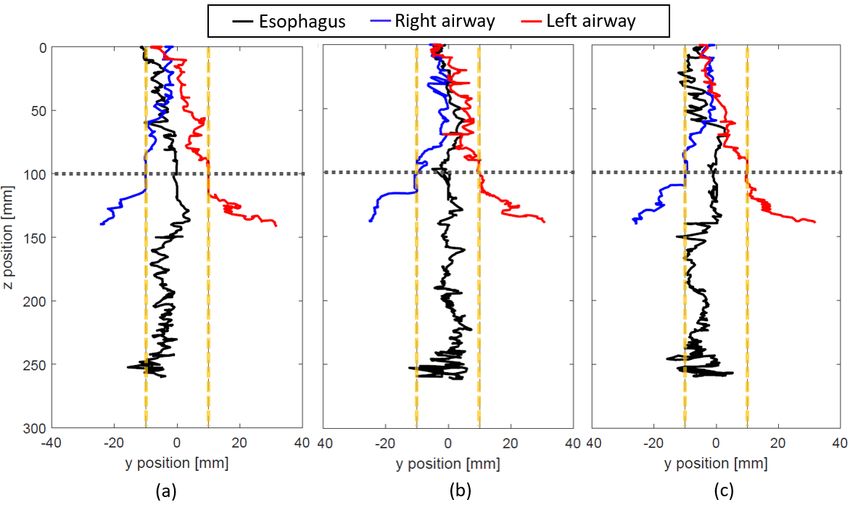
Sensors 2021, 21, 4491                                                                                                   7 of 17

                         Figure 3. Top: Illustration of the search regions, global search range, and instantaneous search range.
                         Bottom: Definition of pitch and roll rotations and the origin of the magnet (Om ).

                         •    Region 0: This region is used until the first estimation is provided. The target magnet
                              will be out of the sensor’s sensible range at the beginning of the NGT insertion. As the
                              insertion progresses, the tip of the tube will enter the search range always from the
                              top. Therefore, we need to focus only on the top slice of the entire search range. Since
                              the insertion speed and the anatomy or tilt angle of the esophagus and trachea are
                              limited, the search ranges can be constrained as follows:

                                                       R Iz = ztop , ztop + vmax dt ∈ ztop , z0                     (7)

                                                       R I p = 0, θ p,max ,                                         (8)

                              where ztop is the top end of the z search range, vmax is the possible maximum speed of
                              tube insertion, dt is the time step in between the iterations, z0 is the first estimation of
                              z position, and θ p,max is the possible maximum pitch angle of the tube tip inside the
                              esophagus and trachea.
                         •    Region 1: This region covers from the first estimated z position to the level of the
                              carina or end of the trachea. The search ranges are constrained based on the current
                              position, orientation, speed of the tube tip and the possible tilt angle of the tube tip
                              inside the esophagus and the trachea.

                                             R Iz = [zk − vmax dt − zunc , zk + vmax dt + zunc ] ∈ (z0 , zcar]              (9)
                                                    h                                             i
                                             R I p = θ p,k − φR1 − θ p,unc , θ p,k + φR1 + θ p,unc ∈ 0, θ p,max            (10)

                              where zk and θ p,k are the estimated z position and pitch angle at the kth iteration. zcar
                              is the z position of the carina. zunc and θ p,unc are the uncertainties from the estimation
                              errors. φR1 is the possible pitch rotation during one computational iteration inside the
                              esophagus and trachea.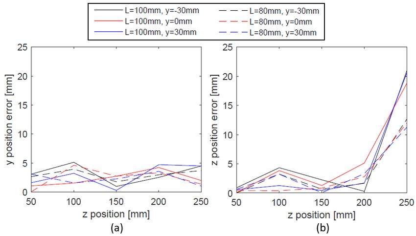
Sensors 2021, 21, 4491 8 of 17
• Region 2: This region covers from the end of region 1 to the bottom end of the search
range. The tube tip could be inside the trachea, bronchi, esophagus, or stomach.
Therefore, any pitch angle is possible.
R Iz = [zk − vmax dt − zunc , zk + vmax dt + zunc ] ∈ (zcar , zbottom ] (11)
h i
R I p = θ p,k − φR2 − θ p,unc , θ p,k + φR2 + θ p,unc ∈ [0, π ], (12)
where zbottom is the bottom end of z search range and φR2 the possible pitch rotation
during one computational iteration inside the trachea, bronchi, esophagus and stomach.
2.2.3. Threshold Modulation
The result of the grid search is significantly affected by the search threshold Bthresh j
which is used in the search condition in Equation (3). For each sensor, n j sets of solutions
are found from the grid search but if the found sets are too many or too few, the following
process of finding the overlap becomes challenging. Real-time tracking will fail if n j is too
large and tracking itself will fail if n j is too small. It is found that n j is dependent on the z
position of the target magnet and the threshold is dependent on the magnitude of Bsensor j .
Therefore, Bthresh j ,k+1 (Bthresh j at k + 1th iteration) is controlled to obtain the right amount
of solution sets using the following proportional derivative (PD) controller type modulator:
de j,k
Bthresh j ,k+1 = Bthresh j ,k + K p j ,k (z)e j,k + Kd j ,k (13)
dt
where
K p j ,k (z) = α(z)| Bsensor j ,k | (14)
Kd j ,k = β| Bsensor j ,k | (15)
e j,k = ntarget − n j,k (16)
de j,k e j,k − e j,k−1
= (17)
dt t k − t k −1
Bthresh j ,k is the search threshold at the k-th iteration. K p j ,k (z) is the proportional
gain vector and Kd j ,k is the derivative gain vector at the kth iteration. α(z) and β are the
modulation coefficients for the proportional gain and for the derivative gain respectively.
e j,k represents the error between the number of the targeted sets ntarget and the detected
sets at the kth iteration n j,k . The time at the k − 1th and kth iteration are denoted tk−1 and
tk respectively.
In addition, the overlap threshold Pthresh12 directly affects the computation of the
final estimation. Depending on the values of the overlap threshold, no overlap could
be detected even if the grid search results from the pairs of the sensors contain virtually
identical values. Real-time tracking could fail if too many overlaps are found. The overlap
threshold contains five components; x, y, z, θ p , and θr .
Pthresh12 = Pthresh12,x Pthresh12,y Pthresh12,z Pthresh12,p Pthresh12,r (18)
Pthresh12 is updated at every iteration based on the values of zest , n1 , n2 , and N12 .
Details (i.e., how and what values are selected) are described in the following section.
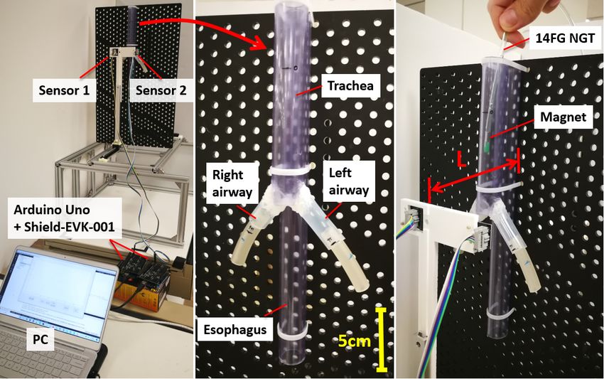
2.3. Experimental Setup
We perform two different experiments to investigate the performance of the two-
sensor-based magnetic tracking system for NGT. In the first experiment, the position
tracking accuracy is evaluated. The magnet is placed at various locations on the frontal
planes with L (distance from the sensors to the magnet along the sagittal axis) = 80 and
100 mm. The reference (ground truth) position of the magnet was measured/set using
manual linear sliders with 1 mm marks. The experimental setup and the locations tested in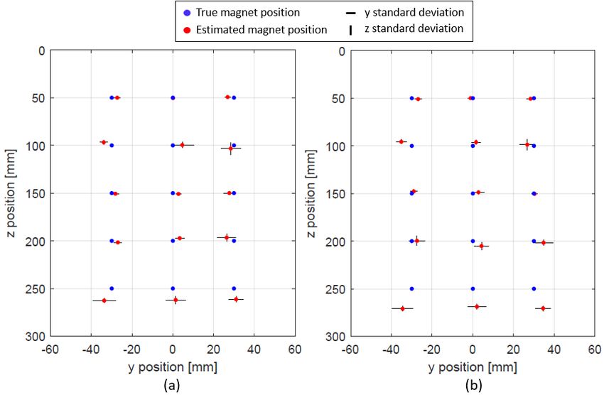
Sensors 2021, 21, 4491                                                                                                9 of 17

                         the frontal plane are illustrated in Figure 4. The tracking was run for 5 s (which results in
                         roughly 250 to 400 data points) for each location. Assuming the sensors are placed on the
                         chest skin 100 mm below the start of the trachea/esophagus, this experiment can check the
                         tracking accuracy within the esophagus and airway where the NGT can enter.
                               In the second experiment, we used a mock-up esophagus and airway constructed
                         using silicone tubes (Figure 5). The inner diameters of the tubes for the esophagus, trachea,
                         main bronchi, and lobar/segmental bronchi are selected to be 20, 20, 15, and 10 mm
                         respectively based on the anatomy of the average adult, and the other dimensions are set
                         as indicated in Figure 2 [21,32–34]. The NGT with the permanent magnet is inserted into
                         each pathway separately to examine whether each tracking result is distinct enough for
                         reliable misinsertion detection. To show the variation of the tracking performance, the NGT
                         is inserted into each pathway three times. The experiment is performed for L = 80 and
                         100 mm. For both experimental setups, the materials used near the sensors and magnet
                         are all non-magnetic. Although some magnetic materials are used in the linear sliders for
                         position adjustment, they are sufficiently distanced from the tracking range and have no
                         effect on the tracking performance. To smooth out the short-term fluctuations or outliers in
                         the raw estimation result, a moving average filter was applied with a fixed subset size of 5.

                         Figure 4. (a) The first experimental setup to test the position tracking accuracy. (b) The tracking
                         accuracy was evaluated at the 15 locations indicated in blue dots.
Sensors 2021, 21, 4491 10 of 17
Figure 5. Mock-up esophagus and airway for the second experiment. The 14 FG NGT with a magnet
is manually inserted into each path (esophagus, right airway, and left airway).
The parameters for the instantaneous search ranges used for the experiment are
summarized in Table 1. We use ztop = 0 and zbottom = 250 mm considering the global search
range described in Section 2.2.2. zcar is determined based on the average anatomy and d
is selected arbitrarily. The average NGT insertion time with and without the CORTRAK
EMS-EAS is reported to be 28.8 s and 369.6 s respectively, while the average NGT insertion
length is up to 730 mm [35,36]. Therefore, the average insertion speed can be as fast as
25 mm/s. To ensure the tracking with sudden and unexpectedly high insertion speed, vmax
is selected to be four times larger. For φR1 and φR2 , since there is no literature regarding the
rotational speed of the tube tip, the values are empirically determined. zunc and θ p,unc are
set to be the same as the step size of the precalculated magnetic field.
Table 1. The parameters for the instantaneous search range.
Parameter Value
ztop 0 mm
zbottom 250 mm
zcar 100 mm
yc 80 mm
vmax 100 mm/s
θ p,max1 5π/18
φR1 π/18
φR2 π/9
zunc 10 mm
θ p,unc π/18
For the PD modulator, ntarget is selected to be 500 to balance the computational time
and the tracking accuracy. Then, the parameters for the PD modulator are adjusted
manually as experiments are carried out until the output from the modulator stays near the
target value. α(z) is shown in Table 2 and β is determined to be 0.01. The value for Pthresh12
is also adjusted manually such that N12 always becomes approximately 500. The values and
conditions are summarized in Table 3. When multiple conditions are met simultaneously,
the condition toward the top of the list is prioritized.Sensors 2021, 21, 4491 11 of 17
Table 2. Value of α that depends on the range of zest .
zest [mm] α(zest )
0 120
(0, 20] 100
(20, 80] 70
(80, 120] 80
(120, 180] 40
(180, 220] 80
(220, 290] 90
greater than 290 100
Table 3. Conditions for selecting Pthresh12 and the corresponding values for each component. The con-
ditions toward the top of the list are prioritized when multiple conditions are met.
Pthresh12
Condition x, y, z, and θ p θr
Components Component
0 ≤ zest < 2.5 0.4 0.8
n1 or n2 < 100 1.25 2.5
n1 and n2 < 500 1 2
500 < N12 0.5 1
100 < N12 ≤ 500 0.75 1.5
50 < N12 ≤ 100 1 2
0 < N12 ≤ 50 1.75 3.5
N12 = 0 2.5 5
3. Results
The result of testing tracking accuracy are presented in Figure 6. The average estimated
magnet position and the SD for each axis are plotted together with the true magnet position.
For most of the positions, the estimation is very close to the actual position of the magnet
except when z = 250 mm where z and y position errors appear to suddenly increase. The y
and z-axis errors along the z position are plotted in Figure 7. While there is no obvious trend
of y position error change along z-axis, z-position error suddenly increases for z = 250 mm.
This could be because the magnet is too far from the sensors and the magnetic field is too
small to provide an accurate estimation. Table 4 shows the RMSE of y and z position as well
as the RMSE when the result of z = 250 mm is excluded. For both L = 80 mm and 100 mm,
we observed decent y tracking accuracy with below 3 mm RMSE. When the average of
all the experiments are taken, z position RMSE for L = 80 and 100 mm are 3.55 mm and
5.50 mm. On the contrary, when disregarding the result of z = 250 mm, the z tracking
RMSE becomes less than 2 mm.Sensors 2021, 21, 4491 12 of 17
Figure 6. The average y and z position error and SD for L = (a) 80 mm and (b) 100 mm.
Figure 7. The average position error and SD along z-axis for (a) y position and (b) z-position.
The results for both L = 80 and 100 mm are shown.
Table 4. RMSE for L = 80 and 100 mm.
y z y z
[mm] [mm] [mm] [mm]
(Excluding z = 250 mm)
80 2.60 3.55 2.47 1.44
L [mm]
100 2.83 5.50 2.62 1.84
The result of the tracking when NGT is inserted into the dimensionally correct mock-
up esophagus and airways is shown in Figures 8 and 9 (for L = 80 and 100 mm respectively).
Since the NGT is smaller than the size of the mock-up esophagus and airways, the insertion
path is different for every trial. It is observed that the tracking for all the trials stays mostly
within the vertical dashed lines which indicate the inner diameter of the esophagus when
the NGT is inserted into the esophagus. When the NGT goes into the airways, we observeSensors 2021, 21, 4491 13 of 17
large deviations of the y position which are right below the sensor level (z = 100 mm)
and outside the vertical dashed lines. As this deviation is very distinct, it can be used
to determine the erroneous insertion. Although the tracking may go beyond the vertical
dashed lines for esophagus insertion, it only happens near z = 250 mm and therefore, it
should not be considered as misinsertion.
Figure 8. Tracking experiment with the dimensionally accurate mock-up esophagus and airway
when L = 80 mm. Three trials of inserting the NGT into each path (the esophagus (black), right
airway (blue), and left airway (red)) are shown in (a–c). The inner diameter of the esophagus and
trachea is represented by the yellow vertical dashed lines. The horizontal dashed line indicates the
vertical location of the sensors.
Figure 9. Tracking experiment with the dimensionally accurate mock-up esophagus and airway
when L = 100 mm. Three trials of inserting the NGT into each path (the esophagus (black), right
airway (blue), and left airway (red)) are shown in (a–c). The inner diameter of the esophagus and
trachea is represented by the yellow vertical dashed lines. The horizontal dashed line indicates the
vertical location of the sensors.Sensors 2021, 21, 4491 14 of 17
4. Discussion
In this work, a laptop PC with a relatively high-performance CPU is used. The NDI
Aurora system has a 40 Hz update rate which is considered adequate for real-time track-
ing [15]. Since the current system achieved a tracking frequency from 50 to 70 Hz, there is
a potential to meet the requirement of real-time tracking by using even lower-performing,
lower-cost PCs.
The experiments indicated the z-axis tracking accuracy decreased below z = 250 mm.
Although the magnitude is different, a similar trend was observed for both L = 80 and
100 mm. If the error increases in a spatially consistent manner, the error might be com-
pensated. We plan to use a neural network or machine learning to identify the spatial
characteristic of the error along the z-axis.
The experiments were performed without biological tissue in between the sensors and
the NGT. This is because it was found that the tracking performance will not be affected
by the biological tissue in the study we previously carried out [17]. The magnetic field
generated by live humans ranges from 20 fT to 1 nT [37]. Therefore, it is out of the sensible
range of the sensor we employed and it will not affect the tracking performance.
Metal implants may affect the tracking performance depending on the material, size,
and location. Therefore, we will investigate to determine whether the system can be
appliable for patients with implants.
In this work, the system was tested at room temperature (25 ◦ C). For the real applica-
tion, the magnet’s temperature will increase due to the body core temperature which is
about 37 ◦ C. Since the strength of the magnetic field is dependent on temperature, the effect
of the temperature on the tracking performance needs to be investigated.
Our system is compared to the one developed in [15] side-by-side in Table 5. The num-
ber of sensors required for our system is about one-fifth of that in the latter system. Since
the tracking volume is not specifically stated in their work, it was deduced from the experi-
mental setup and results. Although the tracking volume may be similar, coverage of the
airway beyond the main bronchi or the entire esophagus is lacking, due to its placement at
the neck. The RMSE of our system is slightly worse when considering the entire range but
excluding z = 250 mm, our system may outperform their system.
Table 5. Comparison of the tracking performance of the proposed and the other magnetic sensor-based
tracking systems. For our approach, the RMSE when z = 250 mm is excluded is in the parenthesis.
Proposed Ref [15]
# of sensors 2 11
Volume [mm3 ] 100×120×250 100×100×200
Magnet size [mm] Φ3.2 × L9.6 Φ3.2 × L9.6
RMSE in 1D [mm] 2.60 − 5.50 0.92 − 4.05
(1.44 − 2.62)
One limitation is our approach will not work when the magnet/NGT is already inside
the tracking range as the initialization or offsetting of the background magnetic field is
unable to be performed. This means the presented approach is not capable of confirming
the location of the already inserted NGT which is necessary for patients with NGT for
the long term. In addition, since the magnet is embedded inside the NGT, the patients
with these NGT are not able to take MRI scans when necessary. Therefore, it would be
advantageous to make the magnet removable and re-insertable.
The other limitation is that no tracking is available beyond the EG junction (cardia).
This is enough to fulfill the goals of this work, but providing tracking for the rest of the
stomach can be useful in confirming the final location of the NGT, for increased patient
safety. Furthermore, when the tubes need to be delivered to the deeper GI tract such as
nasoduodenal and nasojejunal intubations, the tracking range needs to be amplified further.Sensors 2021, 21, 4491 15 of 17
It can be done by employing more accurate sensors and a stronger permanent magnet (i.e.,
N55 grade) or another set of sensors placed around the stomach area.
5. Conclusions
This work presents a low-cost, two-sensor-based magnetic tracking system for NGT
insertion. Using the grid search combined with a dynamically adjusted search range and
PD threshold modulator, we achieved real-time tracking of a magnet embedded at the tip
of the NGT. The tracking accuracy and range obtained from the experiments indicate that
the presented system is capable of detecting the deviation of the position in the frontal
plane to determine when the tube wrongly progresses into the bronchi.
To move forward, the system needs to be tested in humans. For safety, it is ideal to
make the magnet removable after NGT insertion. Therefore, a magnet should be connected
to a guidewire instead of embedding in the NGT. The coating/material of the magnet and
the guidewire should be carefully selected to ensure biocompatibility with and resistance
against gastric acid.
Although this work focuses on the application for NGT insertion, the proposed
system could be applied for tracking the MIBC, endoscopic capsules, and other medical
devices [38–40].
Author Contributions: Conceptualization, M.M.; Data curation, M.M.; Formal analysis, M.M.;
Funding acquisition, S.J.P.; Investigation, M.M., H.L. and K.V.T.; Methodology, M.M., H.L. and K.V.T.;
Software, M.M.; Supervision, S.J.P.; Validation, M.M.; Visualization, M.M.; Writing and original draft,
M.M.; Writing, review and editing, H.L. and K.V.T. All authors have read and agreed to the published
version of the manuscript.
Funding: This research was funded by Nanyang Technological University start up grant num-
ber M4081419.
Institutional Review Board Statement: Not applicable.
Informed Consent Statement: Not applicable.
Data Availability Statement: The data presented in this study are available on request from the
corresponding author.
Acknowledgments: The authors would like to thank the members of the Robotics Research Centre at
Nanyang Technological University for their support and contribution throughout the entire project.
Conflicts of Interest: The authors declare no conflict of interest.
Abbreviations
The following abbreviations are used in this manuscript:
EG Esophagogastric
EM Electromagnetic
EMS-EAS Electromagnetic sensor guided enteral access system
GI Gastrointestinal
MIBC Magnetically inflated balloon capsule
NGT Nasogastric tube
PD Proportional-Derivative
PM Permanent magnet
SD Standard deviation
References
1. Hodin, R.A.; Bordeianou, L. Inpatient Placement and Management of Nasogastric and Nasoenteric tubes in Adults; UpToDate Inc.:
Waltham, MA, USA, 2019.
2. Smithard, D.; Barrett, N.A.; Hargroves, D.; Elliot, S. Electromagnetic sensor-guided enteral access systems: A literature review.
Dysphagia 2015, 30, 275–285. [CrossRef] [PubMed]
3. Stayner, J.L.; Bhatnagar, A.; McGinn, A.N.; Fang, J.C. Feeding tube placement: Errors and complications. Nutr. Clin. Pract. 2012,
27, 738–748. [CrossRef] [PubMed]Sensors 2021, 21, 4491 16 of 17
4. Metheny, N.A.; Meert, K.L.; Clouse, R.E. Complications related to feeding tube placement. Curr. Opin. Gastroenterol. 2007,
23, 178–182. [CrossRef]
5. Agency, N.P.S. Patient Safety Alert NPSA/2011/PSA002: Reducing the harm caused by misplaced nasogastric feeding tubes in
adults, children and infants. Support. Inf. 2011. Available online: http://www.gbukenteral.com/pdf/NPSA-Alert-2011.pdf
(accessed on 29 June 2021)
6. Peter, S.; Gill, F. Development of a clinical practice guideline for testing nasogastric tube placement. J. Spec. Pediatr. Nurs. 2009,
14, 3–11. [CrossRef] [PubMed]
7. Taylor, S.; Allan, K.; McWilliam, H.; Manara, A.; Brown, J.; Toher, D.; Rayner, W. Confirming nasogastric tube position with
electromagnetic tracking versus pH or X-ray and tube radio-opacity. Br. J. Nurs. 2014, 23, 352–358. [CrossRef]
8. Ackerman, M.; Mick, D.; Bianchi, C.; Chiodo, V.; Yeager, C. The Effectiveness of the CORTRAK™ Device in Avoiding Lung
Placement of Small Bore Enteral Feeding Tubes. Am. J. Crit. Care 2004, 13, 253–276.
9. NICE. CORTRAK 2 Enteral Access System for Placing Nasoenteral Feeding Tubes. 2016. Available online: https://www.nice.org.
uk/advice/mib48/resources/cortrak-2-enteral-access-system-for-placing-nasoenteral-feeding-tubes-pdf-63499172779717 (ac-
cessed on 21 April 2021).
10. Pham, D.; Aziz, S.M. A real-time localization system for an endoscopic capsule using magnetic sensors. Sensors 2014, 14, 20910–
20929. [CrossRef]
11. Song, S.; Li, B.; Qiao, W.; Hu, C.; Ren, H.; Yu, H.; Zhang, Q.; Meng, M.Q.H.; Xu, G. 6-D magnetic localization and orientation
method for an annular magnet based on a closed-form analytical model. IEEE Trans. Magn. 2014, 50, 1–11. [CrossRef]
12. Dai, H.; Yang, W.; Xia, X.; Su, S.; Ma, K. A three-axis magnetic sensor array system for permanent magnet tracking. In Proceedings
of the 2016 IEEE International Conference on Multisensor Fusion and Integration for Intelligent Systems (MFI), Baden-Baden,
Germany, 19–21 September 2016; pp. 476–480.
13. Hu, C.; Ren, Y.; You, X.; Yang, W.; Song, S.; Xiang, S.; He, X.; Zhang, Z.; Meng, M.Q.H. Locating intra-body capsule object by
three-magnet sensing system. IEEE Sens. J. 2016, 16, 5167–5176. [CrossRef]
14. Wu, X.; Hou, W.; Peng, C.; Zheng, X.; Fang, X.; He, J. Wearable magnetic locating and tracking system for MEMS medical capsule.
Sens. Act. A Phys. 2008, 141, 432–439. [CrossRef]
15. Sun, Z.; Foong, S.; Maréchal, L.; Tan, U.X.; Teo, T.H.; Shabbir, A. A non-invasive real-time localization system for enhanced
efficacy in nasogastric intubation. Ann. Biomed. Eng. 2015, 43, 2941–2952. [CrossRef] [PubMed]
16. Burdett, E.; Mitchell, V. Anatomy of the larynx, trachea and bronchi. Anaesth. Intensive Care Med. 2011, 12, 335–339. [CrossRef]
17. Miyasaka, M.; Tiong, A.M.H.; Phan, P.T.; Huang, Y.; Kaan, H.L.; Ho, K.Y.; Phee, S.J. Two Magnetic Sensor Based Real-Time
Tracking of Magnetically Inflated Swallowable Intragastric Balloon. Ann. Biomed. Eng. 2021, 1–12. [CrossRef]
18. Bleys, R.L.; Weijs, T.J. Surgical anatomy of esophagus. In Minimally Invasive Surgery for Upper Abdominal Cancer; Springer:
Berlin/Heidelberg, Germany, 2017; pp. 11–20.
19. Jaeger, J.M.; Titus, B.J.; Blank, R.S. Essential anatomy and physiology of the respiratory system and the pulmonary circulation. In
Principles and Practice of Anesthesia for Thoracic Surgery; Springer: Berlin/Heidelberg, Germany, 2019; pp. 65–92.
20. Ball, M.; Falkson, S.R.; Adigun, O.O. Anatomy, angle of Louis 2020. Available online: https://www.ncbi.nlm.nih.gov/books/
NBK459336/ (accessed on 29 June 2021)
21. Mi, W.; Zhang, C.; Wang, H.; Cao, J.; Li, C.; Yang, L.; Guo, F.; Wang, X.; Yang, T. Measurement and analysis of the tracheobronchial
tree in Chinese population using computed tomography. PLoS ONE 2015, 10, e0123177. [CrossRef]
22. García, H.F.; Valencia Orgaz, O.; López Vicente, R.; Gutiérrez Vidal, S.E. Airway anatomy for the bronchoscopist: An anesthesia
approach. Rev. Colomb. Anestesiol. 2014, 42, 192–198. [CrossRef]
23. Seneterre, E.; Paganin, F.; Bruel, J.; Michel, F.; Bousquet, J. Measurement of the internal size of bronchi using high resolution
computed tomography (HRCT). Eur. Respir. J. 1994, 7, 596–600. [CrossRef]
24. Sehgal, I.S.; Dhooria, S.; Ram, B.; Singh, N.; Aggarwal, A.N.; Gupta, D.; Behera, D.; Agarwal, R. Foreign body inhalation in the
adult population: Experience of 25,998 bronchoscopies and systematic review of the literature. Respir. Care 2015, 60, 1438–1448.
[CrossRef]
25. Bellemare, F.; Jeanneret, A.; Couture, J. Sex differences in thoracic dimensions and configuration. Am. J. Respir. Crit. Care Med.
2003, 168, 305–312. [CrossRef] [PubMed]
26. Chubar, O.; Elleaume, P.; Chavanne, J. A 3D Magnetostatics Computer Code For Insertion Devices, SRI97 Conf. Aug. 1997.
J. Synchrotron Rad 1998, 5, 481–484. [CrossRef]
27. Elleaume, P.; Chubar, O.; Chavanne, J. Computing 3D magnetic fields from insertion devices. In Proceedings of the 1997 Particle
Accelerator Conference (Cat. No. 97CH36167), Baden-Baden, Germany, 19–21 September 2016; Volume 3, pp. 3509–3511.
28. Berkelman, P.; Bozlee, S.; Miyasaka, M. Interactive rigid-body dynamics and deformable surface simulations with co-located
maglev haptic and 3D graphic display. Int. J. Adv. Intell. Syst. 2013, 6, 289–299.
29. Berkelman, P.; Miyasaka, M.; Anderson, J. Co-located 3D graphic and haptic display using electromagnetic levitation. In
Proceedings of the 2012 IEEE Haptics Symposium (HAPTICS), Vancouver, BC, Canada, 4–7 March 2012; pp. 77–81.
30. Berkelman, P.; Bozlee, S.; Miyasaka, M. Interactive dynamic simulations with co-located maglev haptic and 3d graphic display.
In Proceedings of the International Conference Advances in Computer-Human Interactions, Nice, France, 24 February–1 March
2013; pp. 324–329.Sensors 2021, 21, 4491 17 of 17
31. Miyasaka, M.; Berkelman, P. Magnetic levitation with unlimited omnidirectional rotation range. Mechatronics 2014, 24, 252–264.
[CrossRef]
32. Ferhatoglu, M.F.; Kıvılcım, T. Anatomy of esophagus. In Esophageal Abnormalities; IntechOpen: London, UK, 2017. [CrossRef]
33. Breatnach, E.; Abbott, G.C.; Fraser, R.G. Dimensions of the normal human trachea. Am. J. Roentgenol. 1984, 142, 903–906.
[CrossRef] [PubMed]
34. Lee, J.W.; Son, J.S.; Choi, J.W.; Han, Y.J.; Lee, J.R. The comparison of the lengths and diameters of main bronchi measured from
two-dimensional and three-dimensional images in the same patients. Korean J. Anesthesiol. 2014, 66, 189. [CrossRef] [PubMed]
35. Rao, M.; Kallam, R.; Flindall, I.; Gatt, M.; Macfie, J. Use of Cortrak® —An electromagnetic sensing device in placement of enteral
feeding tubes. Proc. Nutr. Soc. 2008, 67. [CrossRef] [PubMed]
36. Taylor, S.J.; Allan, K.; McWilliam, H.; Toher, D. Nasogastric tube depth: The ‘NEX’guideline is incorrect. Br. J. Nurs. 2014,
23, 641–644. [CrossRef]
37. Williamson, S.J.; Kaufman, L. Biomagnetism. J. Magn. Magn. Mater. 1981, 22, 129–201. [CrossRef]
38. Kaan, H.L.; Phan, P.T.; Tiong, A.M.H.; Miyasaka, M.; Phee, S.J.; Ho, K.Y. First-in-man feasibility study of a novel ingestible
magnetically inflated balloon capsule for treatment of obesity. Endosc. Int. Open 2020, 8, E607. [CrossRef]
39. Phan, P.T.; Tiong, A.M.H.; Miyasaka, M.; Cao, L.; Kaan, H.L.; Ho, K.Y.; Phee, S.J. EndoPil: A magnetically actuated swallowable
capsule for weight management: Development and trials. Ann. Biomed. Eng. 2020, 49, 1–11.
40. Mateen, H.; Basar, R.; Ahmed, A.U.; Ahmad, M.Y. Localization of wireless capsule endoscope: A systematic review. IEEE Sens. J.
2017, 17, 1197–1206. [CrossRef]You can also read