Harvard University Unmanned Aerial Systems - auvsi suas
←
→
Page content transcription
If your browser does not render page correctly, please read the page content below
Harvard University Unmanned Aerial Systems
                         2019 AUVSI SUAS Competition

                                              Abstract
   The Unmanned Aerial Systems (UAS) team from the Harvard Undergraduate Robotics Club (HURC)
has designed a simple and robust aerial system to attempt the tasks of the 2019 AUVSI SUAS competition.
The team consists of 15 individuals with expertise in Computer Science, Electrical Engineering, Mechanical
Engineering, Mathematics, and Physics who haved worked in close cooperation to create a plane capable of
achieving mission deliverables. The team has implemented a comprehensive mission planning platform, a
high-throughput communications system, and a state-of-the-art vision processing engine. These have been
packaged into a modular fixed-wing aircraft that can fly reliably. Throughout the year, Harvard UAS has
rigorously tested the system and fortified its robustness. During the competition, we seek to demonstrate
the mission capabilities with full autonomy.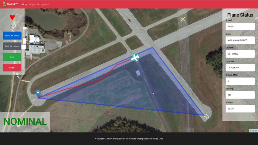
Contents
1 Systems Engineering Approach                                                                                                                                               3
  1.1 Mission Requirement Analysis . . . . . . .        .   .   .   .   .   .   .   .   .   .   .   .   .   .   .   .   .   .   .   .   .   .   .   .   .   .   .   .   .    3
  1.2 Design Rationale . . . . . . . . . . . . . . .    .   .   .   .   .   .   .   .   .   .   .   .   .   .   .   .   .   .   .   .   .   .   .   .   .   .   .   .   .    4
       1.2.1 Equipment and Experience . . . . .         .   .   .   .   .   .   .   .   .   .   .   .   .   .   .   .   .   .   .   .   .   .   .   .   .   .   .   .   .    4
       1.2.2 Budget . . . . . . . . . . . . . . . . .   .   .   .   .   .   .   .   .   .   .   .   .   .   .   .   .   .   .   .   .   .   .   .   .   .   .   .   .   .    4
       1.2.3 Mission Requirement Prioritization         .   .   .   .   .   .   .   .   .   .   .   .   .   .   .   .   .   .   .   .   .   .   .   .   .   .   .   .   .    4
       1.2.4 Design Decision Flow . . . . . . . .       .   .   .   .   .   .   .   .   .   .   .   .   .   .   .   .   .   .   .   .   .   .   .   .   .   .   .   .   .    4

2 System Design                                                                                                                                                              5
  2.1 Aircraft Systems . . . . . . . . . . . . . . . . . . . . . . . .                  .   .   .   .   .   .   .   .   .   .   .   .   .   .   .   .   .   .   .   .   .    5
       2.1.1 Aerial Platform . . . . . . . . . . . . . . . . . . . .                    .   .   .   .   .   .   .   .   .   .   .   .   .   .   .   .   .   .   .   .   .    5
       2.1.2 Flight Controller . . . . . . . . . . . . . . . . . . .                    .   .   .   .   .   .   .   .   .   .   .   .   .   .   .   .   .   .   .   .   .    6
  2.2 Ground Station . . . . . . . . . . . . . . . . . . . . . . . .                    .   .   .   .   .   .   .   .   .   .   .   .   .   .   .   .   .   .   .   .   .    7
       2.2.1 Compute Hardware . . . . . . . . . . . . . . . . .                         .   .   .   .   .   .   .   .   .   .   .   .   .   .   .   .   .   .   .   .   .    7
       2.2.2 Mission Control . . . . . . . . . . . . . . . . . . . .                    .   .   .   .   .   .   .   .   .   .   .   .   .   .   .   .   .   .   .   .   .    7
  2.3 Communications . . . . . . . . . . . . . . . . . . . . . . .                      .   .   .   .   .   .   .   .   .   .   .   .   .   .   .   .   .   .   .   .   .    8
  2.4 Vision System . . . . . . . . . . . . . . . . . . . . . . . . .                   .   .   .   .   .   .   .   .   .   .   .   .   .   .   .   .   .   .   .   .   .    8
       2.4.1 Image Capture Hardware . . . . . . . . . . . . . .                         .   .   .   .   .   .   .   .   .   .   .   .   .   .   .   .   .   .   .   .   .    9
       2.4.2 Transmission Subsystem . . . . . . . . . . . . . . .                       .   .   .   .   .   .   .   .   .   .   .   .   .   .   .   .   .   .   .   .   .    9
       2.4.3 Object Detection, Classification, and Localization                         .   .   .   .   .   .   .   .   .   .   .   .   .   .   .   .   .   .   .   .   .   10
  2.5 Obstacle Avoidance . . . . . . . . . . . . . . . . . . . . . .                    .   .   .   .   .   .   .   .   .   .   .   .   .   .   .   .   .   .   .   .   .   11
  2.6 Air Drop . . . . . . . . . . . . . . . . . . . . . . . . . . . .                  .   .   .   .   .   .   .   .   .   .   .   .   .   .   .   .   .   .   .   .   .   12
  2.7 Cyber Security . . . . . . . . . . . . . . . . . . . . . . . . .                  .   .   .   .   .   .   .   .   .   .   .   .   .   .   .   .   .   .   .   .   .   13

3 Safety, Risks, and Mitigation                                                                                                                                             13
  3.1 Developmental Risks and Mitigation . . . . . . . . . . . . . . . . . . . . . . . . . . . . . . . . .                                                                  13
  3.2 Mission Risks and Mitigation . . . . . . . . . . . . . . . . . . . . . . . . . . . . . . . . . . . . .                                                                13

4 Conclusion                                                                                                                                                                15

5 Acknowledgments                                                                                                                                                           15

6 References                                                                                                                                                                15

Harvard Undergraduate Robotics Club                                                                                                                     Page 2 of 15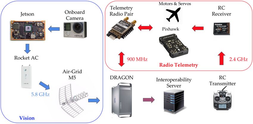
1 Systems Engineering Approach 1.1 Mission Requirement Analysis
                                                           The mission demonstration consists of an exe-
    The 2019 SUAS Mission is to develop an Un-
                                                       cution of the simulated package delivery mission.
manned Aerial Vehicle (UAV) to deliver a package
                                                       The team first receives mission details and launches
to a customer while avoiding obstacles, identifying
                                                       the UAV. It precomputes an optimal flight plan that
potential drop locations, dropping the package
                                                       will be carried out during the competition. While
to a safe location, and then moving the package
                                                       completing waypoint navigation, the UAV uses
to the customer’s location [1]. The UAV was
                                                       vision algorithms to detect, classify, and localize the
manufactured and tested to perform these tasks
                                                       alphanumeric and person of interest. The UAS then
autonomously with as much reliability, safety, and
                                                       deploys an Unmanned Ground Vehicle (UGV) to
efficiency as possible. The system is capable of au-
                                                       deliver a package to a specified coordinate. Table
tonomous flight, obstacle avoidance, alphanumeric
                                                       1 describes an analysis of each of the mission tasks.
image recognition, autonomous target detection,
and air delivery.

 Task              Description                                     Successful Mission Requirements

 Timeline          • Complete mission with minimal flight and      • Well-practiced full mission tests
 (10%)               post processing time.                         • Completion of the mission as quickly
                   • Refrain from timing out.                        and safely as possible

 Autonomous        • Fly, takeoff, and land autonomously with      • Flight testing of the developed au-
 Flight (20%)        minimal manual interference.                    topilot to ensure performance within
                   • Fly the entire waypoint sequence and get        the 100 ft error margin
                     within 100 ft of each waypoint.
                   • Uploading valid telemetry to Interop Sys-
                     tem at average 1Hz.

 Obstacle          • Upload valid telemetry to the Interop         • Create mission plan that avoid sta-
 Avoidance           System at average 1Hz.                          tionary obstacles
 (20%)             • Avoid the stationary obstacles given by
                     the Interop System.

 Object            • Correctly identify characteristics of stan-   • Create accurate simulation of compe-
 Detection,          dard objects and emergent objects               tition environment
 Classification,   • Provide the GPS location of objects within    • Optimize pixels on target to meet
 Localization        150 ft range                                    both user-defined constraints and
 (20%)             • Submit objects from first flight                UAS flight capabilities
                   • Submit and match objects autonomously
                     as much as possible

 Air Delivery      • Drop a 40 oz. UGV and 8 oz. water bottle      • Design and deploy of the UGV that
 (20%)               no more than 75 ft from target.                 accommodates the payload
                   • Accurately drive to GPS coordinates with
                     the water bottle and stop with 10 ft.

 Operational       • Complete the mission in minimal flight        • Team acts professionally and safely
 Excellence          and post-processing time.                       throughout operation.
 (10%)             • Refrain from timing out.

                                  Table 1: Mission Requirement Analysis

Harvard Undergraduate Robotics Club                                                              Page 3 of 15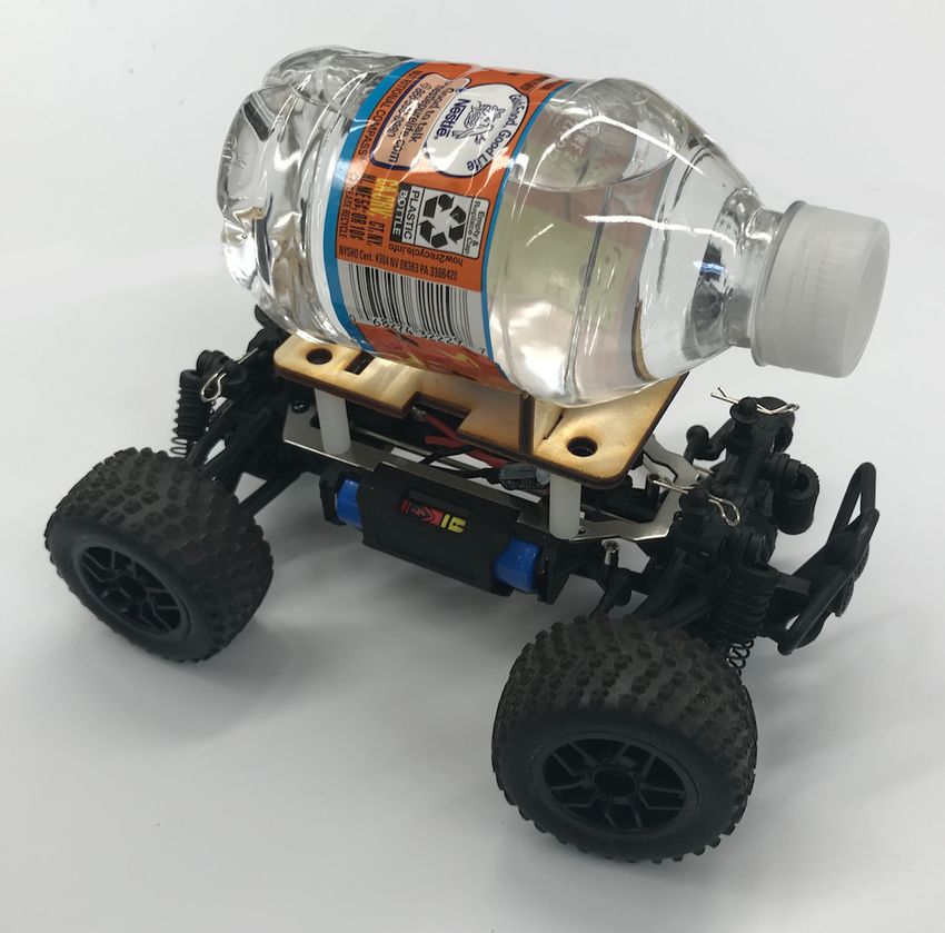
1.2     Design Rationale                                1.2.4   Design Decision Flow
    Because the team is relatively new, our design          The team’s first decision was between modifying
decisions centered around developing a simple           a current aircraft or developing our own. We
aircraft that would perform the mission tasks within    decided to purchase an RC aircraft and modify it
the rules of the competition. This influenced the       for the mission due to time constraints. Despite the
development of all aspects of the system, from          costs, this reduced research and development time
airframe selection to software development.             significantly and allowed the team to focus on our
                                                        goal of developing a minimum-viable aircraft.
1.2.1   Equipment and Experience                            Having attended the AUVSI competition in
                                                        2018, we learned that the RMRC Anaconda kit plane
    Harvard UAS is based out of the Harvard             was a popular starter platform among teams. Addi-
Undergraduate Robotics Club (HURC) and consists         tionally, we saw that having a robust aircraft that
of fifteen undergraduate students. The group has        could withstand wind was a serious consideration
access to an electronics lab as well as a machine       in platform selection; this was the key factor that
shop. Additionally, we obtained access to the           influenced our decision to commit to a fixed-wing
Odyssey computing cluster operated by the Har-          plane over a drone. Following up on research into
vard Faculty of Arts and Sciences (FAS) Division of     the Anaconda plane, we discovered that it was easy
Science, Research Computing (RC) Group to train         to maneuver, had a low cost, and sported a large
our machine learning model for object detection and     carrying capacity. Thus, we decided to use the
classification.                                         Anaconda for this year’s competition.
                                                            Because of the familiarity we had with the
1.2.2   Budget                                          Pixhawk from the previous year, we decided to
                                                        continue running our software on the platform
    Our team had a budget of $9,000. We allocated
                                                        because of its affordability, reliability, and flexibility
$5,000 to prototype and build the aircraft and
                                                        with integrating sensors such as the GPS, IMU, and
ground vehicles, $1,000 on the imaging system, and
                                                        barometer.
$3,000 for competition and travel expenses.
                                                            We had an Jetson TX1 processor donated to us
                                                        from NVIDIA. This processor is both performant
1.2.3   Mission Requirement Prioritization              and power-efficient, allowing us to run some degree
    Due to the small size of our team, we understood    of computation—especially preprocessing for the
that correctly prioritizing the various mission tasks   vision task—on-board the aircraft. After deciding
was paramount to our success. Our first priority        that we would use the Jetson, we purchased an
was to fly our plane autonomously while avoiding        Orbitty Carrier Board for the processor to mount it
stationary obstacles.     Once this was achieved,       in the aircraft.
we were focused on fulfilling the vision mission            We then decided to use the GoPro Hero 4 Silver
requirements of alphanumeric classification and         because of its low cost, light weight, and capacity
emergent target detection. Lastly, we decided that      for high-resolution wide-angle video streaming. For
this task would be a lower priority deliverable for     these reasons, we decided that it would be ideal for
this year’s team.                                       our mission of detecting, classifying and localizing
                                                        alphanumeric and emergent vision targets.
                                                            After that, we needed to connect back to the
                                                        ground station using a wireless system. To achieve
                                                        this objective, we used an Ubiquiti Rocket M5
                                                        receiver on the plane, which creates a WiFi network
                                                        connection with our ground-based Ubiquiti AirGrid
                                                        M5 antenna, which in turn connects to our Ground
                                                        Station Network. We also used a RFD900+ radio for
                                                        telemetry.
                                                            Finally, we chose our Mission crew based on
                                                        their experience and interests in relation to our
                                                        design decisions. We aimed to maximize our talents
           Figure 1: Design decision flow
                                                        and efficiency.

Harvard Undergraduate Robotics Club                                                                 Page 4 of 15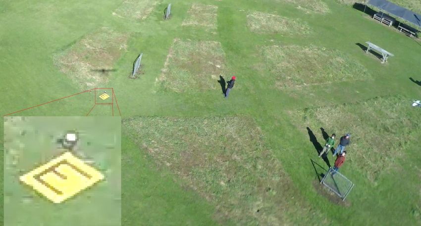
Figure 2: Aircraft system

2 System Design                                          autonomous flight, but not for the pilot controlling
                                                         the aircraft.
                                                            Our propulsion system consists of a lithium
2.1     Aircraft Systems                                 polymer 4S, 10aH battery and a 820 Kv brushless
   In this section, we describe the design of our Air-   motor that rotates a 15 x 4E wooden propeller.
craft, Ground, Software, and support infrastructure      With this configuration, we found that we can
systems as shown in Figure 2. We further discuss         achieve a flight time of about 30 minutes before
how these design decisions meet our mission design       the aircraft needs to land. We wanted to achieve
objectives.                                              a balance between speed and flight time, and this
                                                         configuration proved to be the most optimal.
2.1.1   Aerial Platform
    Because the Anaconda is a kit RC Plane, its
structure, and therefore its aerodynamic charac-
teristics, were mostly predetermined. Thus, our
main focus in its construction was maintaining its
structural rigidity. To accomplish this, we utilized
a combination of adhesives, namely JB Weld R Steel
Glue and Hardener, Epoxy R , and dedicated foam
glue.
    We deemed the aerodynamic capabilities of the
Anaconda sufficient to meet the demands of the
competition. Without making any modifications
to the kit plane, we calculated a coefficient of lift
during cruise flight of 0.059. Assuming we would
need about 0.5 extra kilograms of lift force for         Figure 3: Labeled aircraft. (1) Inverted v-tail, (2)
takeoff, we can achieve takeoff at around 16.8 m/s.      Motor and propeller, (3) Tail boom, (4) Ailerons,
We anticipate that going with an anhedral (wings         5 Rear landing gear, (6) Fuselage cover, (7) Nose
sloped downward) might be better for the aircraft in     landing gear, (8) Air inlet

Harvard Undergraduate Robotics Club                                                             Page 5 of 15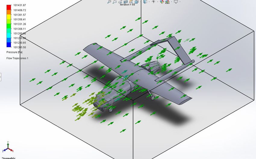
Figure 6: Aircraft flow

                                                         2.1.2     Flight Controller

                                                            We use a Pixhawk 2.0 running the ArduPilot
   Figure 4: Anaconda aircraft with dimensions           3.10.0 Firmware to control the aircraft.     This
                                                         controller is a commercial board popular in the
                                                         drone community. A diagram of how the Pixhawk
                                                         controller connects to our aircraft system can be
                                                         seen in Figure 7.

           Figure 5: Wing strain analysis

    Using SolidWorks Simulation and Flow Simula-
tion, we were able to analyze the wing loading and
airflow around the aircraft, helping us to verify that
the aircraft is capable of performing the mission.
Figure 5 shows the wing strain analysis. Figure 6                       Figure 7: Labeled Pixhawk
displays the wind flow through the aircraft.

  General Aircraft Specifications           Wing Specifications                          Powerplant
  Empty weight           5.27 lbs            Airfoil        Clark Y             Type                Electric
      MTOW              12.13 lbs        Chord Length        0.98 ft
                                                                               Motor           Cobra C520/12
    Wingspan              6.76 ft         Aspect Ratio           8.66
                                                                                              820 Kv Brushless
    Stall speed         24.61 mph
                                                                               Battery          10,000 mAh
   Cruise speed         35.8 mph
                                                                              Propeller             15 x 4E

                                       Table 2: Aircraft specifications

Harvard Undergraduate Robotics Club                                                                   Page 6 of 15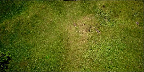
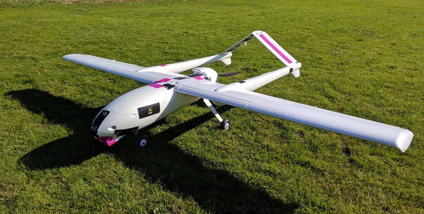
Figure 8: Block diagram depicting SnakePIT module organization and interaction.

2.2     Ground Station                                 2.2.2   Mission Control
    The purpose of the Ground Station is to serve as       In order to handle the custom mission objec-
a central control hub for the plane and mission. It    tives required by the competition, we created our
is also intended as a powerful off-plane computing     own purpose-built Mission Control System called
platform, which allows us perform much more            the “Snake” Project Interface Terminal (SnakePIT).
complex computations at a much more affordable         SnakePIT consists of a web-based Graphical User
price-point than is possible with a computer aboard    Interface, which allows for easy plane-control by
the plane.                                             the pit crew, a persistent database to store mission
                                                       state and logs, and a task queue to run image
2.2.1   Compute Hardware                               processing and mission monitoring tasks in parallel.
    We call our self-built computing and command       Additionally, the SnakePIT webserver provides an
station the Dedicated Research and Ground Oper-        API to integrate the various software components
ated Nexus (DRAGON). The DRAGON is designed            of our platform, ranging from a wrapper for the
to have powerful image processing capabilities in      Interoperability Server API to simplify mission
order to effectively analyze the images incoming       requests to direct plane control through what we
from the NVIDIA Jetson on the plane.                   call the Body Orientation API (BOA). An overview
    In order to do this, the DRAGON is equipped        of the organization of the SnakePIT modules is
with a GeForce RTX 2080 8Gb GPU, a Ryzen 5 3.4         illustrated in Figure 8.
GHz 6-Core Processor, 16Gb of DDR4 Ram, and                SnakePIT was written in Python 3.6 using the
500Gb of M.2-2280 Solid State Storage. In order        Django webserver framework, with Celery for task
to keep the components in a durable, but light-        handling.
weight and easily portable casing, we re-purposed a        SnakePIT handles mission planning automati-
salved PowerMac-G5 casing, which is made purely        cally. Simply with the push of a “START MISSION”
of anodized aluminum and has built-in handles          button on the web-interface, SnakePIT pulls mis-
for carrying. The ground station will be running       sions from the Interoperability Server, computes a
Ubuntu in order to streamline communication be-        obstacle-avoiding path for the plane, and uploads
tween the plane and interop server.                    this flight plan to the plane via BOA.

Harvard Undergraduate Robotics Club                                                           Page 7 of 15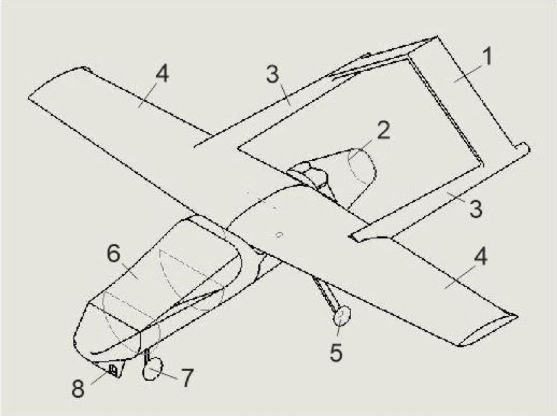
Figure 9: Screenshot of the SnakePIT Command Dashboard.

2.3   Communications                                    we two distinct radio links for direct control of
                                                        the plane’s Pixhawk flight control system. We use
    Our COmmunications BRoadcast Antenna Sys-           a 2.4GHz receiver for manual flight control by a
tem (COBRAS) is responsible for sending and             ground-based Futaba T14SG Transmitter operated
receiving flight control and vision data to and from    by our pilot. Additionally, we use a pair of RFD-
the plane, conveying this data between our various      900+ Radio Modems operating at 900 MHz for
computing systems, and relaying computed output         long-range two-way serial communication with the
to the competition Interoperability Server. An          Pixhawk. The Futaba uses frequency hopping to
overview of the connectivity provided between our       avoid interference in transmission, and the RFD-
systems depicted in Figure 2.                           900+ radios employ encryption and unique radio
    We use a Ubiquiti AirGrid M5 and a Ubiquiti         channels to avoid interference and enable secure
Rocket M5 to establish a 5.8GHz WiFi link between       mission control.
the plane and ground network. The use of WiFi
and the particular choice of these devices was          2.4   Vision System
due to their excellent high-throughput, error-free
transmission and good performance at 1km. The               The role of the Vision System, dubbed the
purpose of this WiFi link is to primarily transmit      Very Intelligent PERception (VIPER) System, is to
image data captured on-board the plane, so this         find and capture images of standard and emergent
network design is well-suited to this application.      targets, and to process these images for the Object
    The Rocket M5 is linked to the on-plane Jetson      Detection, Classification, and Localization (ODCL)
computer by ethernet cable, and the AirGrid M5 is       component of the mission. Specifically, the VIPER
linked to a ground-based Netgear router by ethernet     System must
cable. The DRAGON Ground Station Computer is
                                                          1. Capture sufficiently detailed images of
connected to this router by ethernet as well, and the
                                                             ground objects, including human targets and
Interoperability Server is linked to the WAN side of
                                                             pattern targets;
this router.
    In addition to our Wifi communication system,         2. Automatically crop ground objects detected in

Harvard Undergraduate Robotics Club                                                            Page 8 of 15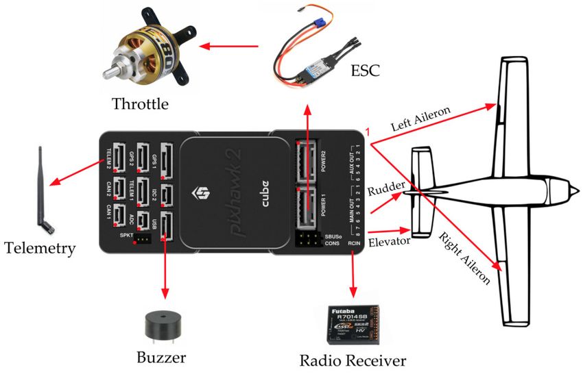
these images;                                      we describe our design choices for these capture,
                                                        transmission, and ODCL components of the Vision
  3. Compute the estimated GPS location of these        System, and why we made these design choices to
     objects;                                           optimize for our four engineering objectives above.
  4. Automatically describe the content of the
     detected target; and                               2.4.1   Image Capture Hardware

  5. Submit these findings to the Interoperability
     Server.

   To best meet these tasks, we decided that the
engineering objectives to optimize in the VIPER
System were speed, sufficiency, robustness, and
affordability:

   • Speed is the ability to capture, transmit, and
     process image data quickly. This is important
     because the plane has a high enough ground
     speed that there will be significant position
                                                        Figure 10: Sample field-of-view of the GoPro Hero
     changes in each frame so that missing too
                                                        4 Silver at 100ft, with zoomed target to show the
     many frames due to slow processing may
                                                        pixel-size of the captured target.
     result in gaps in the vision search area.
                                                            We decided to use a single fast, wide-angle
   • Sufficiency means that the image quality           video camera that is capable of capturing a wide
     must be high enough to enable deep analysis        field-of-view. The camera selected for this purpose
     and cropped submissions with satisfactory          was the GoPro Hero 4 Silver, which can capture
     resolution. This is important because our          3840x2160px video at 15FPS.
     object detection algorithms use deep-learning          This solution satisfies Speed, since the single
     models that require sufficient resolution in or-   video stream can be quickly transmitted and con-
     der to accurately locate objects. Additionally,    tinually processed; in contrast, using a shuttered
     the competition requires that images clear for     camera introduces delay for image capture, and
     judging.                                           using multiple cameras could introduce bottlenecks
   • Robustness is the quality of the hardware to       in transmission. It satisfies Sufficiency because
     be tolerant of rough conditions (a crash, for      the 4K resolution provides enough pixels for the
     example) and of the software to be tolerant        targets at the minimum flying height that our
     of adverse vision conditions (rain, noise from     deep-vision models are able to detect them (see
     faulty hardware, dislodgement from wind or         Figure 10), and the 15FPS framerate allows for
     crash damage). This is important because real      overlap between the fields-of-view between frames
     mission conditions can create imperfect input      at our plane’s expected ground speed. The solution
     which nonetheless must be processed to meet        satisfies Robustness because the GoPro is designed
     competition objectives.                            to be durable and can be placed in its manufactuer-
                                                        designed protective case. Finally, it satisfies Afford-
   • Affordability is the goal of minimizing the        ability because a one-camera system is low-cost,
     financial and time costs of developing the sys-    and because we were able to acquire the GoPro in
     tem. This is important because our resources       particular from our inventory at no cost.
     are limited, as we are a relatively new orga-
     nization with a relatively small development       2.4.2   Transmission Subsystem
     team.
                                                           We decided to stream our captured video from
   To meet these objectives, we designed a system       the plane to our Ground Station Computer for
which uses a single fast, wide-angle video camera       processing. This primarily allowed us to use more
to capture video that is streamed to our Ground         powerful hardware purchased at a better compute-
Station Computer for processing. In this section,       power-per-price, satisfying the Affordability objec-

Harvard Undergraduate Robotics Club                                                               Page 9 of 15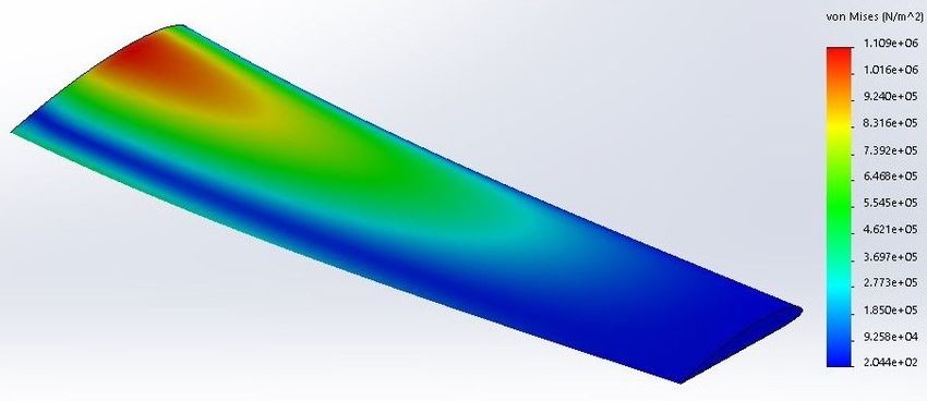
tive. Robustness was also important in this deci-                            the ROI is an emergent target, it is presented
sion, as a crash or other damage to our plane would                          for manual captioning.1
not jeopardize expensive compute equipment.
    We opted to use a 5.8GHz WiFi connection                              7. Additional proprietary heuristic techniques
for the transmission channel, as it would be fast                            are employed to filter out false-positive ROIs.
enough to quickly send high-resolution video across
competition-length distances, satisfying Speed and
Sufficiency.
    To these ends, we used an NVIDIA Jetson
TX1 (available to us as a generous donation from
NVIDIA) running VLC to compress the video and
serve it as a UDP stream over the COBRAS commu-
nications backend described in the previous section.
We chose VLC because it uses the production-grade
FFMPEG library to transcode and stream video, and
we chose UDP as a transmission protocol because it
allows for dropped frames without delay, which is                     Figure 11: A sample artificially-generated training
important for Robustness and Speed.                                   image. Note the barely-visible target in the lower
                                                                      middle-left. We expected this to be a representative
                                                                      example of what a target would look like from the
2.4.3     Object Detection, Classification, and Local-
                                                                      plane.
          ization
    Our Object Detection, Classification, and Lo-
calization (ODCL) algorithm is called the VIPER
Algorithm. For the VIPER Algorithm, we chose to
use a combination of deep-vision processing and
heuristic techniques to highlight target candidates
on the ground:

   1. The image (example: Figure 11) is pre-
      processed (resized, sliced, and normalized)
      and fed into an image-segmentation neural
      network, which produces a pixel-by-pixel
                                                                      Figure 12: The actual segmentation mask, which
      classification (example: Figure 13) of back-
                                                                      was generated automatically by our training image
      ground pixels vs. pixels which constitute
                                                                      generator. The mask highlights the location of the
      regions-of-interest (ROIs).
                                                                      target in the image.
   2. We use a blob-detection algorithm to extract
      the location and bounds of these ROIs.

   3. For each ROI, the relative position of the ROI
      in the image is used along with the plane’s
      GPS position and altitude and information
      about the camera’s field of view to compute
      the estimated GPS location of the ROI.

   4. The ROI is cropped.

   5. A number of proprietary heuristic techniques
      are applied to filter out false-positive ROIs.                  Figure 13: VIPER Algorithm segmentation predic-
                                                                      tion. The yellow pixels indicate a predicted region-
   6. If the ROI is a standard pattern target, it is                  of-interest. Note how close it is to the actual mask
      passed through a classificaiton algorithm. If                   in Figure 12!
  1 In   the future, we plan to also use a deep learning model to automatically caption the image.

Harvard Undergraduate Robotics Club                                                                           Page 10 of 15
For the image-segmentation network, we used GPU-enabled compute cluster.
Mask R-CNN2Go [2], which is a fast, slim, and accu- The cropped and classified images are presented
rate modern image segmentation network. The net- on the SnakePIT Vision Panel for review. They are
work is small enough that our DRAGON Ground automatically submitted after a number of seconds.
Station Computer is capable of processing multiple If, during this time, there is something drastically
frames per second. The image-segmentation net- incorrect about the submission, the SnakePIT Vision
work was trained using artificially-generated train- Panel allows the team to intervene and edit or
ing images, which were created by superimposing stop the submission. This procedure allows for au-
generated targets (with varying shape, color, and tonomous image submission with the opportunity
symbol for standard targets and a number of sample for manual intervention if necessary.
human objects for emergent targets). The network All of this image processing software is imple-
was trained on several hundred thousand of these mented in Python 3.6, making heavy use of OpenCV
images over 24 hours on the Harvard University for general image processing and heuristics and
Faculty of Arts and Sciences (FAS) Division of Sci- Keras and Tensorflow for the image-segmenation
ences, Research Computing (RC) Group’s Odyssey network.
Figure 14: RRT from red to green blocks while avoiding white obstacles
2.5 Obstacle Avoidance module is initialized with descriptions of mission
constants such as the coordinates of each flyzone
Before the start of the mission, we use the bound, as well as the coordinates, radius, and
Rapidly-Exploring Random Tree (RRT) algorithm altitude of each obstacle. The module can then be
[3] to plot the initial path of the plane to avoid set to navigate from a set of starting coordinates
obstacles. We chose the sampling-based RRT to a set of end coordinates. The Planning method
algorithm (shown in Figure 14) due to its wide produces a path avoiding all obstacles from start
usage for path planning of mobile robots. The point to end point, given in a list of coordinates
Harvard Undergraduate Robotics Club Page 11 of 15to follow in order. In the driving function in the The drop mechanism is a simple single servo
mission planning, we call the RRT function from powered quick release system. We chose this to
the starting point to the first waypoint, the first minimize the number of active mechanisms, and for
waypoint to the second waypoint, and so on until its reliability. The servo pulls out the pin that holds
we are done with the waypoints. This output will be the UGV inside the plane. The UGV is dropped with
an array of coordinate pairs for the plane to follow. a parachute attached.
There is no description of altitude since we will aim To conduct the drop, we add waypoints to
to keep the plane at a constant altitude for optimal our path planning subsystem. We first add a
performance of our VIPER system. waypoint at the drop location. Then, we add
The RRT algorithm works for continuous multi- another waypoint to reach right before the drop
dimensional space because at each expansion step, location waypoint. This waypoint is 30 meters
it picks a random point anywhere in the space and away from the drop waypoint, and is close to the
chooses vertex u, the vertex in the tree closest to it. existing waypoints. We determine this by taking the
The algorithm creates a new vertex v at a constant drop waypoint and the nearest existing waypoint to
expansion distance away from u in the direction that, and drawing a line between them. We add a
of the chosen random point. This step is where waypoint on that line 30 meters away from the drop
we modified the base RRT algorithm for obstacle waypoint.
avoidance. Base RRT would add the new branch Those waypoints allow us to ensure the plane is
(u, v) to the tree. Instead, we iterate through every moving towards the drop target for 30 meters. We
stationary obstacle and check if the line segment drop the UGV when we are x = hk meters away,
(u, v) intersects or is too close to the obstacle. Our where x is a function of height and h is a constant
algorithm checks if the minimum distance between scaling factor.
(u, v) and the center of the obstacle is less than
r + m, where r is the radius of the obstacle and m
is an arbitrary margin. If (u, v) does intersect the
circle, we discard v and try again, choosing another
random point in the space. Otherwise, we add
the new branch (u, v). All of the new branches
added to the tree will thus avoid any obstacles,
which guarantees that our flight path will avoid all
obstacles.
2.6 Air Drop
Our Air Drop subsystem is designed to be robust
and consistent. We began with a thorough analysis
on what we desired from of our Unmanned Ground
Vehicle (UGV), as described in Table 3.
This led us to choose a HobbyKing 1/24 scale
4WD RC vehicle for our UGV. We built a water
Figure 15: UGV carrying payload
bottle holder and an electronics panel for the
car, and modified the casing to feature a quick
release mounting point. We control the UGV using
a GPS sensor, a compass, a gyroscope, and a Desired Characteristic Solution
microcomputer (ESP8226). When the UGV detects Maneuverability Small turning radius
it has landed, using its gyroscope measurements, it
Drive over dynamic High ground
calculates its current GPS position. Then, using the
terrain clearance
compass, it orients itself towards the target position
and drives towards it. It stops once the GPS sensor Avoid getting stuck All wheel drive
indicates the UGV is at the target location. The Survive shocks Suspension
microcomputer is also connected to an RC system
for emergency stop functionality. Table 3: UGV Design Guidelines
Harvard Undergraduate Robotics Club Page 12 of 152.7 Cyber Security 3 Safety, Risks, and Mitigation
Unmanned aerial systems often carry or use
confidential data which, if exploited, have the The team assessed potential risks and delays
potential to cause major damage in a short amount to development inherent to the construction of the
of time. Based on guidelines for cyber emergency system. We collectively strategized ways to mitigate
response teams distributed by the U.S. Department potential risk factors to ensure safe and timely
of Homeland Security, our security protocol has two completion of collective goals. Throughout the
global objectives: construction of the system, we ensured that our
team members remained well-trained in the ma-
1. Reduce the ability of an unauthorized user to chines and techniques they were using and aware
gain access to data and/or disrupt communi- of potential risks to maximize the productivity and
cations safety of our work environment.
2. Facilitate immediate response in the event of a
security breach in order to minimize its effect 3.1 Developmental Risks and Mitiga-
tion
We address the first objective with comprehensive
encryption of both endpoints and all data transmis- During the construction process, the team con-
sion. tinuously reassessed potential risks and reevaluated
our strategies to ensure that we were able to meet
(a) We use WPA2, an AES encryption protocol, construction goals and work towards successful
for our Wi-Fi transmission. We have made completion of the system. Table 4 summarizes the
sure that our SSID is not in the top 1000 of potential risks during development, our assessment
common SSIDs, such that it is not vulnerable of their likelihood and impact, and our approaches
to a Rainbow Table attack. to mitigating them.
(b) We have encrypted the internal hard drives
of both the ground station and the on-board 3.2 Mission Risks and Mitigation
computer with AES-256 bit encryption.
The team assessed potential risks arising from
(c) In addition to a password, we require the the operation of the plane and completion of
ground station user to insert a physical USB missions. They worked to assess the major risks
drive, of which there is only one copy, in order associated with competition and build conditions
to log into the ground station. and redundancy into the system to mitigate such
risks. Table 5 describes how the team mitigated
(d) We utilize the 128-bit AES encryption built mission risks.
into the RFD900 radios to make sure that The team also developed a safety checklist that
our telemetry connection to the Pixhawk stays is consulted before every flight to ensure that all
secure. mechanical, electrical, and software components are
functional and secure. Furthermore, we flew our
We address the second objective with manual
UAV at a designated zone away from any populated
overrides, and frequent security checks.
area and ensured that all personnel were at least 30
(a) In the case of a breach involving the ground feet away from the fly zone.
station, Wi-Fi transmission, or on-board com-
puter, our safety pilot can manually over-
ride any commands given by the computer
through a telemetry radio. This override is
independent of any software, so no attack can
disable it.
(b) Every 5 seconds, an encrypted query is sent
up to the on-board computer that requires
a response; in the case of no response, the
ground team is immediately notified.
Harvard Undergraduate Robotics Club Page 13 of 15Risk Description Risk Level Mitigation Strategy
Personnel Injury that High • Each member was trained before having access.
injury during could be caused • Wearing safety equipment, such as gloves
manufacturing by improper and goggles, was required at all times during
and/or protection and development.
assembly methods. • For access to more specialized machines,
members underwent specialized training with
faculty.
System and/or During testing High • Created a pre-flight checklist.
component of the system, • Trained all the system pilots.
damage components • Obtained backups of key parts in event of
or the aircraft damage.
itself could • Components covers were created.
receive damage. • Components were taped down and weight and
balance was checked.
Equipment Delays in Medium • We ensured that we had multiple copies of key
malfunc- construction parts and tested across multiple versions. We
tion/damage due to part built in time in our schedule to recover from
to parts failure or delays caused by damage or part failure.
improper
construction.
Table 4: Developmental Risks and Mitigation Strategies
Risk Description Risk Level Mitigation Strategy
Unexpected General error Medium In addition to fully testing the autopilot, we
autopilot error with autopilot included a dedicated radio channel for manual
system takeover in case of autopilot failure.
Loss of Loss of Low In the case of a loss of connection, the autopilot was
network connection of programmed to slowly and safely decrease altitude
connection wi-fi network and land the plane.
to onboard
receiver
resulting in
disconnection
from autopilot
Damage Poorly secured Medium We isolated key components within the system,
to internal components ensured they were secured, and created component
components could cause covers.
damage to the
system during
flight.
Table 5: Mission Risks and Mitigation Strategies
Harvard Undergraduate Robotics Club Page 14 of 154 Conclusion We would like to thank the Burlington RC Flyers
group for sharing their expertise in flying planes
In preparation for the team‘s second appearance and allowing us to use their field.
at the AUVSI-SUAS competition, the team wanted We are also grateful to Professor Vijay Reddi for
to build on the progress they had made over its his mentorship and advice at key points during this
previous year. Throughout this year, the team project.
has worked to perfect its UAS through numerous The computations in this paper were run on
systemic design changes and overhaul. The team the Odyssey cluster supported by the FAS Division
doubled down on the fixed wing design, made a of Science, Research Computing Group at Harvard
robust mission planning software (SnakePIT), and University.
experimented with new vision algorithms. Our
primary objective was to design and develop an
elegant aerial system to attempt all of the tasks 6 References
specified by the SUAS guidelines. After careful
testing and planning, the team has ensured that its [1] Association for Unmanned Vehicle Systems
UAS is safe and consistent and that it fulfills as International Seafarer Chapter, ”Competition
many of the requirements as possible. Rules SUAS 2019,” 2018. [Online] AUVSI
SUAS, http://www.auvsi-suas.org/static/
competitions/2019/auvsi_suas-2019-rules.
5 Acknowledgments pdf
[2] Kaiming He, Georgia Gkioxari, Piotr Dollár, and
The team’s work and its finalized UAS would Ross B. Girshick, ”Mask R-CNN,” 2018. [Online]
not have been possible without the generous spon- arXiv, http://arxiv.org/abs/1703.06870
sorship of the Harvard Undergraduate Robotics
Club’s donors: Amazon Robotics, Solidworks, [3] LaValle, Stephen M., ”Rapidly-Exploring Ran-
ROBOTIS, Analytical Space, Jevois, NVIDIA, the dom Trees: A New Tool for Path Planning,”
MIT Lincoln Lab, Maxon Motors, and Advanced 1998. [Online] http://msl.cs.illinois.edu/
Circuits. ~lavalle/papers/Lav98c.pdf
Harvard Undergraduate Robotics Club Page 15 of 15You can also read