Large scale preparation of Co nanoparticles as an additive in carbon fiber for microwave absorption enhancement in C band
←
→
Page content transcription
If your browser does not render page correctly, please read the page content below
www.nature.com/scientificreports
OPEN Large‑scale preparation of Co
nanoparticles as an additive
in carbon fiber for microwave
absorption enhancement in C band
Y. X. Zhu1,2, S. F. Wang1,2, Y. S. Zhang1,2, Z. G. Wu1,2*, B. Zhong3, D. R. Li1,2, F. Y. Wang1,
J. J. Feng1, J. Tang2, R. F. Zhuo1,2 & P. X. Yan1,2
Recent studies have found that the core–shell structured metal nanoparticles and porous carbon
nanofibers (PCNF) are combined into a microwave absorbing material through electrospinning,
which exhibits excellent microwave absorption performance. In this study, the core–shell structure
Co nanoparticles prepared by the self-developed HEIBE process (production rate of > 50 g/h) were
combined with porous carbon fibers, and their absorbing properties were greatly improved. The
morphology of Co/PCNF demonstrated that CoNPs are randomly dispersed in the porous carbon
nanofibers and carbon nanofiber form complex conductive network which enhances the dielectric
loss of the materials. Meanwhile, the Co/PCNF has a low graphitization and shows a significant
improvement in permittivity due to the combination of CoNPs and high conductivity of carbon
material. The maximum reflection loss (RL) of Co/PCNF reaches − 63.69 dB at 5.28 GHz with a
thickness of 5.21 mm and the absorption bandwidth (RL ≤ − 10.0 dB) is 12.92 GHz. In terms of 5.60 mm
and 6.61 mm absorber, there are two absorption peaks of − 47.64 dB and − 48.30 dB appear around
12.50 GHz and 14.10 GHz, respectively. The results presented in this paper may pave a way for
promising applications of lightweight and high-efficiency microwave absorbing materials (MAMs).
With the explosive advance of novel electronic, wireless, and radar devices, which has led to the frequent occur-
rence of such safety problems as human health, national defense security, and electronic safety, e tc1. Microwave
absorbing materials (MAMs) can effectively eliminate electromagnetic waves through electrical loss, magnetic
loss, and impedance matching2,3. The single absorber has disadvantages that can’t meet the requirements of
advanced MAMs, such as narrow absorption band, weak reflection attenuation, thick coating, and high d ensity4,5.
Therefore, many studies in the past have focused on the combination of magnetic material and carbon material,
such as Co-CNTs6, Co/C n anoparticles7, Co/C n anocomposites8,Co/Graphene9, and Co/C-80010, and the purpose
is effectively evaluating and calculating absorption properties by adjustment the relative complex permittivity
(εr = ε′ − jε″) and permeability (μr = μ′ − jμ″). However, the maximum absorption value of this type of absorber is
mainly distributed over a relative narrow frequency range, and this will limit the practical application of light-
weight and high-performance MAMs.
Carbon materials have been widely used in microwave absorbing materials because of their large specific
area, low cost, good stability, low cost, and good electrical conductivity. Carbon materials can be classified into
carbon fiber, carbon nanotubes, carbon black, graphene, and porous carbon. Noticeably, porous carbon fibers
compared with traditional carbon fibers, it has many advantages such as lighter quality, possess many holes on the
surface of the fiber, and more excellent electrical c onductivity11–13. The porous structure of porous carbon fibers
will improve the stability of MAMs. At the same time, due to the existence of a large number of heterogeneous
interfaces between different components, the structure between carbon nanoparticles and magnetic nanopar-
ticles can enhance the polarization of the interface14. Among typical magnetic metals (Fe, Co, and Ni), cobalt
nanoparticles can be considered as ideal magnetic filler candidate, because it has stable chemical properties, large
saturation magnetization, strong anisotropy field and high Snoek’s limit in the GHz range15.
1
School of Physical Science and Technology, Lanzhou University, Tianshui Road, Lanzhou 730000,
China. 2Institute of Nanomaterials Application Technology, Gansu Academy of Science, Dingxi Road,
Lanzhou 730000, China. 3School of Materials Science and Engineering, Harbin Institute of Technology at Weihai,
Weihai 264209, China. *email: zgwu@lzu.edu.cn
Scientific Reports | (2021) 11:2171 | https://doi.org/10.1038/s41598-021-81848-7 1
Vol.:(0123456789)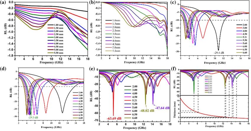
www.nature.com/scientificreports/
In this paper, core/shell structure cobalt nanoparticles (CoNPs) were preparation of macro and added to
polyacrylonitrile/N,N-Dimethylformamide (PAN/DMF) solution containing vegetable oil to prepare Co/C
porous nanofibers (Co/CPNFs) by electrospinning. To the best of our knowledge, there are a few reports about
the combination of porous carbon fibers and magnetic metal nanoparticles. Therefore, in view of these advan-
tages of porous carbon fiber, this work focuses on the synthesis and microwave absorption properties of Co/
PCNF. The Co/PCNF have excellent microwave absorption properties with the maximum absorption value of
− 63.69 dB at 5.28 GHz. Such good absorbing properties are attributed to the combined action of impedance
matching, dielectric loss, magnetic loss, and attenuation constant. This work provides a novel strategy to achieve
the production of MAMs, which has lightweight, strong absorption, wide absorbing band.
Experimental section
Preparation and synthesis. Preparation of the magnetic cobalt nanoparticles. The CoNPs were produced
by a method called HEIBE, which was mentioned in our previous report16. In simple terms, the preparation pro-
cess of CoNPs is as follows: Use ion beam to bombard the cobalt block in a sealed environment with a vacuum of
10−3 Pa. When the heat energy on the surface of the cobalt block reaches a certain level, a large amount of cobalt
vapor will be generated in the vacuum chamber. The condensing cycle system is then used to quickly cool the
cobalt vapor so that it nucleates and crystal grains grow. The oxygen (5 sccm) was passed into the closed cham-
ber to passivate the obtained CoNPs, and an oxide layer was formed on the surface of the CoNPs. Ultimately,
the core–shell structure of CoNPs were collected owing to the rapid homogeneous nucleation and quenching.
Synthesis of the Co/porous carbon nanofibers. the Co/PCNF were synthesized by electrospinning based on an
earlier paper16,17, which is as follows: Firstly, 0.8 g of PAN (Mw = 150,000) was dissolved in 10.0 g of DMF by
magnetic stirring at room temperature, then 1.08 g of vegetable oil and CoNPs were added to the above mixture,
and mechanically stirred at room temperature for 12 h to obtain a stable suspension. The obtained spinning
solution was subjected to ultrasonic treatment for 15 min, and then the spinning solution was transferred to the
disposable syringe for electrostatic spinning. The conditions of electrospinning are as follows: the work distance
was 22 cm, and the work voltage was 30 kV. The feed rate was 30 µL/min. The product is collected by a collector
composed of grounded stainless steel strips (the width between the steel strips is 1 cm), and the spinning pro-
cess Always keep the surface temperature of the collector around 80 °C. The gray product on the collector was
placed in a tube furnace at a heating rate of 2 °C/min at 800 °C for 2 h, and argon gas (50 sccm) was introduced
during the heat treatment. Name the obtained sample S3, and repeat the experiment with the added amount of
CoNPs (0.05 g, 0.26 g), and name the final samples S1 and S2 respectively. Figure 1 illustrated a simple schematic
diagram of the synthesis of magnetic Co/porous carbon nanofiber and how electromagnetic wave attenuation
comes about.
Philips), while using Cu Kα1 (λ = 1.540 Å) radiation. The microstructure and morphology are determined using
Characterizations. The crystal phase is recorded on X-ray powder diffraction (XRD, X’pert powder,
scanning electron microscopy (FIB-SEM, Tescan LYRA 3 XMU), and scanning transmission electron micros-
copy (STEM). The shape and size of the particles were determined from high-magnification transmission elec-
tron microscopy (HRTEM, FEI Tecnai G 2 F30). The degree of graphitization was confirmed by Micro-Raman
spectroscopy (Jobin–Yvon Horiba HR800) using argon ion laser (k = 532 nm) in the range of 800–1800 cm−1. The
pore-size distribution is investigated by Brunauer–Emmett–Teller measurement (BET, ASAP 2020 Micromerit-
ics), and the magnetic properties were carried out by vibrating sample magnetometer (VSM Lake-Shore 7404,
USA) in room temperature.
The EM parameters are analyzed in the test range (2.00–18.00 GHz) by using a vector network analyzer
(VNA, Agilent N5245A). According to the mass ratio of sample to paraffin of 1:5, the sample are pressed into a
toroidal shape (outer diameter of 7.0 mm and inner diameter of 3.04 mm). The calculated reflection loss (RL)
and simulated reflection loss (RL) are calculated by the coaxial reflection/transmission method based on the
NRW method and the transmission line theory, respectively.
Results and discussion
Structure and morphology analysis. The CoNPs have been produced massively at a production rate of
> 50 g/h, the carbon nanofibers were synthesized by electrospinning followed stabilization and carbonization.
The phase composite measured by XRD of Co/PCNF is shown in Fig. 2c, XRD pattern of CoNPs indicates the
CoNPs consist of fcc structure Co (JCPDS 15-0806) and C o3O4 (JCPDS 43-1003). Based on JCPDS card No.
15-0806, three diffraction peaks of cobalt centered at 2θ = 44.2°, 52.4°, and 76.4° are corresponded to (111),
(200), and (220) planes, respectively. The sharp diffraction peaks and high intensity mean that the magnetic
Co core has highly crystallized. Besides, we can observe a very weak peak of Co3O4 coating. This result is in
accord with the HRTEM test results represented in Fig. 2b. Using the Scherrer equation: D = kλ/β1/2cosθ18, where
D is the average crystallite size, k a shape function for which a value of 0.9 is used, λ the X-ray wavelength in
nanometer (nm), β1/2 the full-width at half maximum (FWHM) of the strongest reflection peak (111); thus, the
average grain size of CoNPs is approximately 100 nm. From STEM image (Fig. 2a), it can be seen that CoNPs are
spherical in shape and some particles connected in series. Simultaneously, this result is also in good agreement
with the XRD results. The HRTEM image (Fig. 2b) exhibits that CoNPs are core/shell structure, with a thin shell
(2–5 nm), and combined with results of XRD, we can know that the out layer of particles is cobalt oxide and
core is cobalt element. Furthermore, the lattice fringe of the outer shell is corresponding to (311) crystal plane of
Co3O4, the lattice fringe of the core is corresponding to (111) crystal plane of Co. The XRD pattern of Co/PCNF
is shown in Fig. 2d. Compared to CoNPs, in addition to the peaks of Co and C o3O4 in Co/PCNF, there is also
Scientific Reports | (2021) 11:2171 | https://doi.org/10.1038/s41598-021-81848-7 2
Vol:.(1234567890)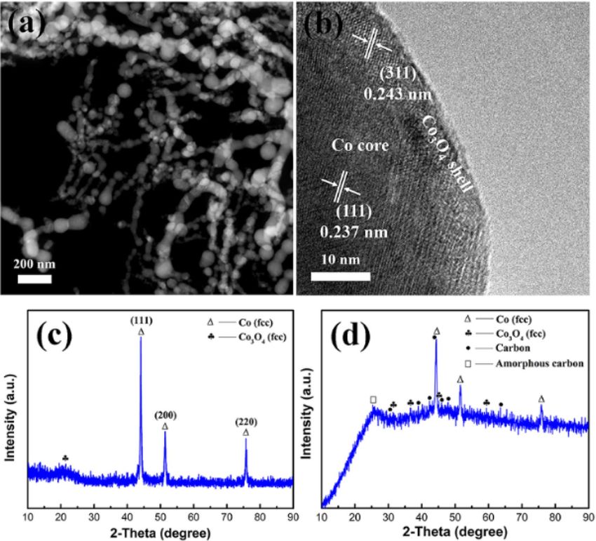
www.nature.com/scientificreports/

                                  Figure 1.  The schematic illustration of the fabrication process of Co/PCNF.

                                  a visible peak in 25.2°, indicating the annealed Co/PCNF contains amorphous carbon, it will be demonstrated
                                  again in the Raman test results.
                                      The morphology and microstructure of Co/PCNF can be investigated by SEM and TEM. The SEM image
                                  (Fig. 3a) indicates that Co/PCNF have 3D cross-linked network structure with entanglement, the average diam-
                                  eter of the fiber ranges from 100 to 500 nm and many pores are distributed on the surface of the fibers. In addi-
                                  tion, there are many entanglements among nanofibers because of irregular entanglement behavior of PAN after
                                  oxidation stability. From STEM images as shown in Fig. 3b,c, it can be seen that the particles with a size less
                                  than 30 nm are embedded in the fibers. Instead, the larger particles are agglomerated around the fiber surfaces.
                                  As shown in Fig. 3d, the Co nanoparticles are very uniformly dispersed in the carbon fiber, which is due to the
                                  long-term ultrasonic treatment and stirring during the preparation of the material. Figure 3f,h demonstrate
                                  the elemental mappings of Co/PCNF, the results show that the compound contains elements Co, C, and O.
                                  Among them, the Co, O are evenly distributed inside the distribution area of carbon. These consequences fur-
                                  therly confirm that the pores with different sizes are distributed randomly in the carbon nanofiber. Besides, the
                                  monodisperse CoNPs are distributed on the surface or inside of the porous carbon matrix homogeneously, it
                                  is due to long time stirring and ultrasonic treatment. To explore the existence of cobalt nanoparticle in carbon
                                  fibers and the phase structure of carbon, the HRTEM images (Fig. 3e, e1) show a part of the crystallization of
                                  carbon materials, but the lattice distortion is not perfect, such as atom deletions, dislocations and lattice fringes
                                  bending. Figure 3e2 shows a typical Co lattice fringe, the result corresponding to the XRD. Above all, we think
                                  that the existence of particles and pores is the main cause of the defects in this composite material, which is
                                  be beneficial to the improvement of absorbing performance. After further estimating the mass percentage and
                                  atomic percentage of each element in S2 by an energy spectrometer, the results are shown in Table 1. It can be
                                  seen that C is the main component element in the sample, and Co content is low. Therefore, it can be concluded
                                  that in the case of a small amount of CoNPs prepared by the HBIE method, the absorption performance of the
                                  absorbent can be significantly improved while the density of the absorbent is kept low.

Scientific Reports |   (2021) 11:2171 |                https://doi.org/10.1038/s41598-021-81848-7                                                    3

                                                                                                                                                Vol.:(0123456789)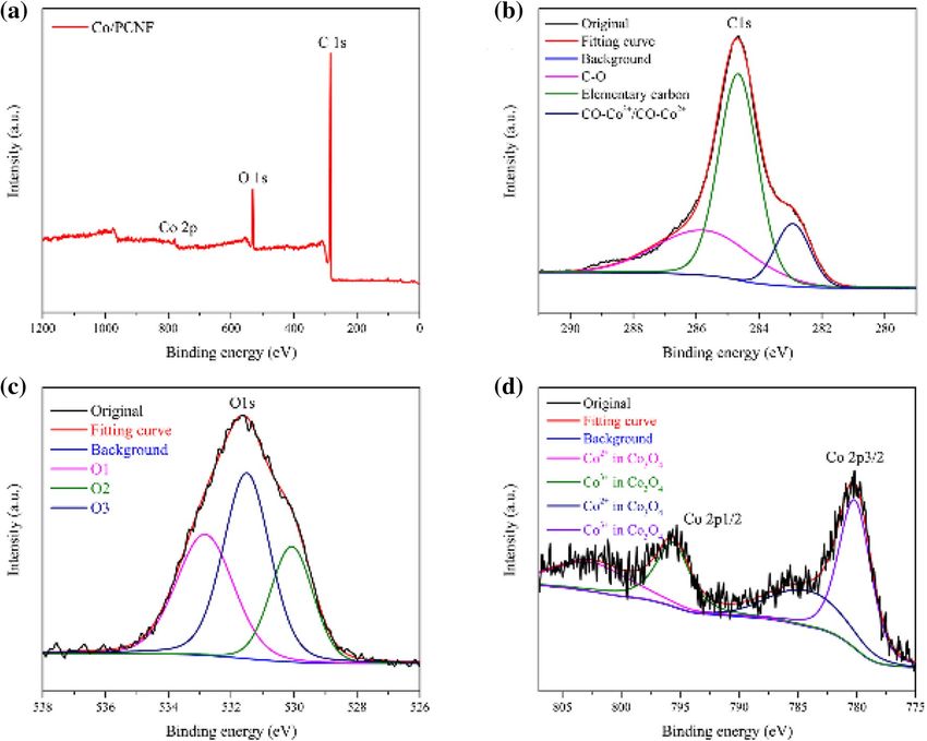
www.nature.com/scientificreports/
Figure 2. (a) STEM image, (b) HRTEM image, (c) XRD pattern of CoNPs, and (d) XRD pattern of Co/PCNF.
Nitrogen adsorption/desorption was used to characterize the porous carbon fiber in order to further com-
prehend the microstructure of pore. The specific surface area and pore size distribution of Co/PCNF were
represented by nitrogen BET as shown in Fig. 4. The S BET of Co/PCNF is 41.48 m2/g and the total pore volume
is 0.0709 cm3/g−1. The formation of porosity is based on the sacrifice template method19.
Raman study and magnetic properties. The banding state of carbon (graphitization degree) in Co/
PCNF can be further studied by Raman spectra20. Figure 5(a) displays the Raman spectra of Co/PCNF. As
reported21, the two broad peaks in the graph represent amorphous carbon (D-band), it is ascribed to the vibra-
tions of sp3 carbon atoms of disordered graphite, indicating the amorphization degree of samples, and graphiti-
zation carbon (G-band), it is related to the in-plane vibration of sp2 carbon atoms in a 2D hexagonal lattice,
which is related to graphite carbon, respectively. The most obvious characteristics of Raman spectroscopies are
the D and G bands at 1350 cm−1 and 1580 cm−1, separately. It can be seen that the intensity ratio (ID/IG) of D
band (1363 cm−1) and G band (1594 cm−1) is 1.05. The degree of graphitization is evaluated by ID/IG7, this result
indicates Co/PCNF contain a certain amount of structural defects and have a low graphitization degree. We
speculate that the reason for the low degree of graphitization of Co/PCNF is that the presence of CoNPs and
pores makes carbon form visible small crystals around it (as shown in Fig. 3e2). Because they are disordered and
not perfect with crystal imperfection, such as, vacancy, interplanar spacing widening and crystal bending, etc.,
resulting in a low degree of Co/CNF graphitization. In addition, CoNPs has good dispersion and is surrounded
by crystal carbon, which improves the corrosion resistance of CoNPs and establishes a good electromagnetic
matching. Based on previous research results, the relative low graphitization degree will be favorable for improv-
ing the impedance matching of microwave absorbing materials7.
To reveal the microwave absorption mechanism of composite materials, Fig. 5b shows the magnetic proper-
ties at room temperature for CoNPs and Co/PCNF. The hysteresis loop shows that the samples have a strong
magnetic response under varying external magnetic field. The saturation magnetization ( Ms), the coercivity
(Hc) values of CoNPs and Co/PCNF are 132.00 emu/g, 24.95 emu/g, and 224.06 Oe, 342.50 Oe, respectively.
Scientific Reports | (2021) 11:2171 | https://doi.org/10.1038/s41598-021-81848-7 4
Vol:.(1234567890)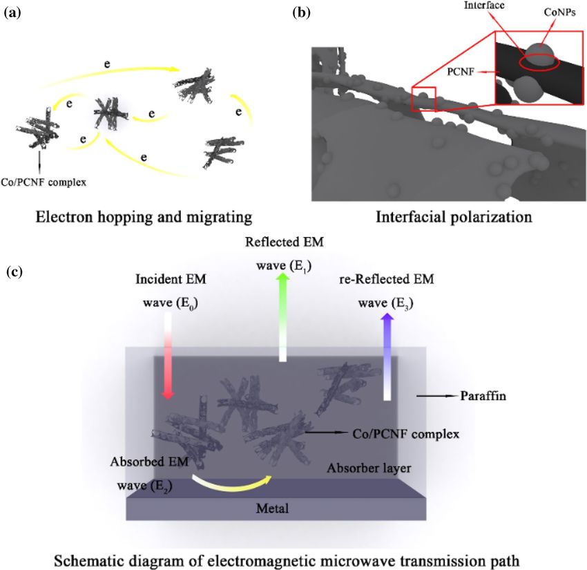
www.nature.com/scientificreports/

                                  Figure 3.  SEM images (a–c) under different magnification, (d) STEM image, (e) HRTEM image of Co/PCNF;
                                  (e1) crystal plane of the carbon around the pore and (e2) crystal plane of CoNPs particles embedded in the
                                  samples; elemental mapping of Co/PCNF in some area of Co/PCNF: (f) carbon mapping; (g) cobalt mapping;
                                  (h) oxygen mapping.

                                   Element   Mass percentage   Atom percentage
                                   C         93.96             97.5
                                   O         2.16              1.68
                                   Co        3.88              0.82
                                   Gross     100               100

                                  Table 1.  X-ray energy spectrum analysis result of Co/PCNF (S3).

Scientific Reports |   (2021) 11:2171 |                https://doi.org/10.1038/s41598-021-81848-7                                              5

                                                                                                                                       Vol.:(0123456789)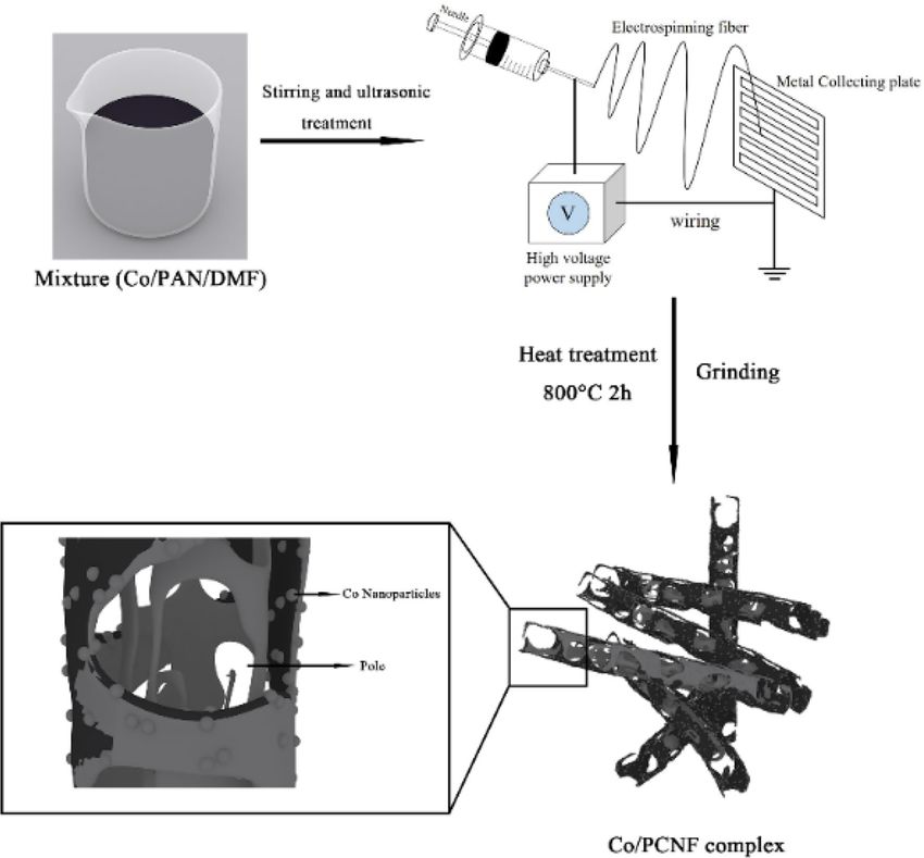
www.nature.com/scientificreports/
Figure 4. (a) Nitrogen adsorption–desorption isotherms and (b) pore size distributions of Co/PCNF.
Figure 5. Raman spectrum (a) of Co/PCNF; hysteresis loop (b) of CoNPs and Co/PCNF at room temperature.
Ferromagnetic MAMs possessing high initial permeability (μi) which decides it has a stronger magnetic loss,
and initial permeability (μi) can be defined by the equation as follows15:
M2S
µi = (1)
akHc Ms + b ξ
where a and b are two constants associated with absorber, λ the magnetization constant, ξ the elastic strain
parameter of the crystal, M s the saturation magnetization and Hc the coercivity. It is reasonable that larger Ms
and smaller H c are the two basic conditions of higher initial permeability (μi)22. It can be seen from Fig. 5b that
CoNPs have larger M s and smaller H c in the case of external magnetic field, and this will enable CoNPs own a
larger initial permeability (μi). Therefore, CoNPs has better magnetic loss ability compared to Co/PCNF, but
the too high magnetic loss will lead to unbalance matching impendence and decrease of microwave absorbing
performance, which will be explained in detail later.
Elemental analysis. X-ray photoelectron spectra (XPS) and X-ray absorption fine structure (XAFS) fur-
ther analyzed the surface composition of Co/PCNF and the valence states of C, Co, O, as shown in Fig. 6. Fig-
ure 6a shows the XPS full spectrum of Co/PCNF, where C, Co and O signals are clearly observed, which means
that the sample is mainly composed of C, Co, O and there are no other impurity elements. This result is consist-
ent with the experimental data of XRD. The C 1s spectrum (Fig. 6b) can be regarded as the fitting correspond-
ing to the three photoemission peaks of CO–Co2+/CO–Co3+, elementary carbon and C–O, located at 282.9 eV,
284.6 eV and 285.7 eV, r espectively56. As shown in Fig. 6c, the O 1s of Co/PCNF show three characteristic peaks
located at 532.8 eV (noted as O1), 530.1 eV (noted as O2) and 531.5 eV (noted as O3), which can be assigned to
hydroxyl groups or surface-adsorbed, oxygen lattice oxygen in pristine Co3O4 and vacancy sites with a low oxy-
gen coordination, respectively57. For the XAFS spectrum of Co, the two fitting peaks of Co2p3/2 and Co2p1/2 are
composed of Co3+ and Co2+, and the area that the fitted curve covered shows the relative atomic ratio of surface
Co2+/Co3+. The ratios of C o2+/Co3+ of the Co/PCNF is 0.65, which is greater than the value of C
o2+/Co3+ of pure
Co3O4. This may be the reason for the deviation of the Co 2p peak of Co/PCNF from the Co 2p peak of pure
Co3O456,57. According to the above results, it can be concluded that C o3O4 exists in Co/PCNF, which is consist-
Scientific Reports | (2021) 11:2171 | https://doi.org/10.1038/s41598-021-81848-7 6
Vol:.(1234567890)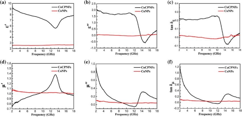
www.nature.com/scientificreports/
Figure 6. Raw scan XPS spectra (a) of Co/PCNF. XPS survey spectrum and deconvolution of Co/PCNF (S1)
(b) C 1s, (c) O 1s, (d) Co 2p.
ent with the XRD results. In addition, through electrospinning and heat treatment, a chemical bond is formed
between CoNPs and the shell (Co3O4) of PCNF.
Microwave absorption property. In order to further explore the microwave absorption characteris-
tics of Co/PCNF, two important parameters, the complex permittivity (εr = ε′ − jε″) and complex permeability
(μr = μ′ − jμ″), were determined by a vector network analyzer23. Specifically, the real part of permittivity ε′ (and
permeability μ′) are related to the storage of electromagnetic energy and the imaginary part of permittivity ε″
(and permeability μ″) represent the loss of electromagnetic e nergy24,25. Two basic electromagnetic parameters
(εr and μr) of CoNPs and Co/PCNF in 2.0 − 18.0 GHz are shown in Fig. 7a,b,d,e. As illustrated in Fig. 7a,b, the
complex permittivity of Co/PCNFs, as the frequency increases, both the real part (ε′) and the imaginary part
(ε″) decrease slightly in 2.0–10.0 GHz. It’s worth noting that this phenomenon of ε′ and ε″ drops sharply in the
high-frequency range (10.0–14.5 GHz) is called frequency dispersion behavior, which is found in most carbon
materials, such as carbon nanotubes (CNT), carbon black, graphene, and porous carbon. Moreover, the appear-
ance of strong resonance peaks of ε′ and ε″ may be associated with the interfaces between Co cores and lattice
defects, because it may lead to the interfacial polarization and interfacial relaxation (as show in Fig. 10b)26.
Compared with Co/PCNF, the values of ε′ and ε″ of CoNPs are fluctuating up and down in the vicinity of 2.6
and 0.05 respectively in whole range of test frequencies, this phenomenon should be caused by the combination
of the inherent dipole orientation polarization in the sample, the interface polarization between the Co particle
core and the graphite carbon shell, and the space charge polarization between adjacent Co particles. As can be
observed in Fig. 7a, the ε′ value of Co/PCNF is much larger than that of CoNPs, suggesting the CoNPs have
poor polarization performance. In addition, the addition of porous carbon nanotubes increases the conductivity
of the composite material and provides an additional conductive path for electron hopping and migrating, as
shown in Fig. 10a, increase the conductivity loss. The presence of more free electrons in the material means that
it can transform high electromagnetic energy, which will be resulted in the increase of the ε′ value21. Not only
that, compared with the carbon fiber composites without porous structure, the slightly inferior of permittivity
for carbon fiber with porous may be due to introduce into the low dielectric air by porous. According to free elec-
tron theory in which ρ = 1/πf ε″ε027,28, where ε0 is a constant of 8.854 × 10⁻¹² F/M, ρ is the resistivity of samples. It
can be known that the higher value of ε″ means lower ρ value. From 2.0 to 13.7 GHz (shown in Fig. 7b), the ε″
value of Co/PCNF is higher than that of CoNPs, indicating CoNPs has a very poor dielectric loss. For Co/PCNF,
Scientific Reports | (2021) 11:2171 | https://doi.org/10.1038/s41598-021-81848-7 7
Vol.:(0123456789)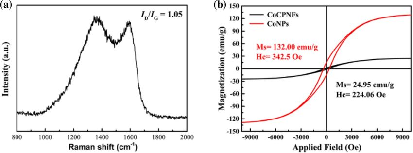
www.nature.com/scientificreports/
Figure 7. Frequency dependence of (a) real parts (ε′) and (b) imaginary parts (ε″) of complex permittivity; (d)
real parts (µ′) and (e) imaginary parts (µ″) of complex permeability; (c) dielectric loss (tanδε) and (f) magnetic
loss (tanδµ) for CoNPs and Co/PCNF.
we should notice that the negative value exists of ε″ in the frequency range of 13.7–16.5 GHz, meaning the Co/
PCNF have no dielectric loss under this circumstance29.
The μ′, μ″ of CoNPs show negligible change from 2 to 18 GHz, and especially the μ″ is close to zero in entire
frequency range. In contrast, when the Co nanoparticles are combined with carbon nanofibers, the real and
imaginary values of magnetic conductive showed obvious trend changes in the test range, these values of Co/
PCNF display drastic variations with frequency increasing as demonstrated in Fig. 7d-e. In Fig. 7d, CoNPs
have higher values of μ′ than Co/PCNF when the frequency is in the range of 2.0–9.5 GHz and 15.8–18.0 GHz.
However, the μ′ values of Co/CPNFs are greater than that of CoNPs in the 9.5–15.8 GHz frequency range, and
shows a peak value of 1.37 in the vicinity of 13.4 GHz. As shown in Fig. 7e, the value of μ″ decreases sharply as
the frequency increases, and is negative in the range of 10.4–12.9 GHz. The value of μ″ is a negative number,
which means that the material has generated magnetic energy and radiated outward due to charge hopping and
migrating. This phenomenon may be caused by the Fabry–Perot resonance, which also appears in such as F e3O4/
SnO2 nanorods30, MWCNT/wax31, and hollow cobalt nanochain composites32. When the frequency is increased
to 12.5 GHz, the μ″ value starts to rise, and clearly see the resonant frequency of the μ″ appears at 14.3 GHz.
Dielectric loss (tanδε) are the best evaluation criteria for the dielectric capacities of material. Therefore, it
is necessary to lucubrate to it. As depicted in Fig. 7c, we can see that the tendency of tanδε correspondingly in
agreement with ε″ over a wide range of frequency, which has a sharp decline after 12.0 GHz and an upward ten-
dency after 14.9 GHz. This is because of the value of tanδε proportional to the value of ε″ through an equation
of tanδε = ε″/ε′. With the increase of frequency, the tanδε. The value of Co/PCNF is larger than that of CoNPs,
showing Co/PCNF have a very strong dielectric loss in a certain frequency. Similarly, for Co/PCNF, the negative
value of tanδε in 13.7–16.9 GHz also proves that there is no dielectric loss in this frequency range. Many research-
ers highlight the importance of magnetic loss (tanδμ) in the analysis of material magnetic loss, in an attempt
to achieve the most suitable matching impedance33. In Fig. 7f, the tanδμ value of Co/PCNF declines from 1.16
to 0.05 in the range of 2.0–12.0 GHz, and then increases to 0.28 at about 14.7 GHz, that’s the same trend as μ″.
However, the tanδμ value of CoNPs is almost constant around 0.05 in the entire measurement frequency range.
It is well concluded that the permeability of absorber is associated with hysteresis loss, eddy current effect,
domain-wall resonance, natural ferromagnetic resonance, and exchange r esonance34–37. In the case of the weak
applied microwave field, the hysteresis loss can be neglected. The domain-wall resonance loss only happens
in multidomain magnetic materials instead of single domain magnetic materials. In this work, CoNPs used
are multidomain magnetic materials whose particle size (Ds = 40.0 nm) is far greater than critical size of the
single magnetic domain (14 nm)38. However, the domain-wall resonance loss can also be excluded because the
domain-wall resonance loss usually exists in a much lower frequency (MHz) range39. In this study, due to the
unique structural features and the small size of the sample, the increase in magnetic loss caused the sample to
generate eddy current loss. In the test frequency range, the contribution of eddy current effect to magnetic loss
can be analyzed by the dependence of c0 = μ″(μ′)−2/f with frequency40. If the value of c0 keep a constant with
increasing frequency, the eddy current loss originated from eddy current effect will be the only reason for the
magnetic loss41. It is clear that the μ″(μ′)−2/f values of CoNPs and Co/PCNF decrease as frequency increases is
a sketch in Fig. 8a, which that means that the eddy current loss is effectively suppressed due to the smaller size
of Co particles. Therefore, the eddy current effect is not the only source of magnetic loss, and also two magnetic
Scientific Reports | (2021) 11:2171 | https://doi.org/10.1038/s41598-021-81848-7 8
Vol:.(1234567890)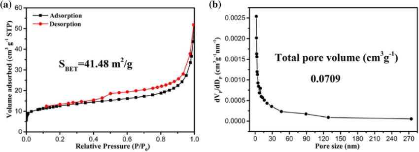
www.nature.com/scientificreports/
Figure 8. (a) The values of μ″(μ′)−2f−1and (b) the values of attenuation constant (α) versus the frequency for Co/
PCNF and CoNPs.
loss mechanisms of natural resonance, exchange resonance, which work together in low frequency range42,43.
The natural resonance can be described by the natural-resonance equation as follows:
2πfr = rHα (2)
Hα = 4|K1|/3µ0 Ms (3)
where r was the gyromagnetic ratio, Ha was the anisotropy energy and |K1| was the anisotropy coefficient. The
natural ferromagnetic resonance may be attributed to the small size effect and the introduction of non-magnetic
materials. In Co/PCNF, due to the surface anisotropic field generated by the small size effect of the material
itself, this effect is significantly enhanced by the nano-scale CoNPs prepared by HEIBE. Not only that, when
non-magnetic materials are introduced, the MS of the sample is lower than the Ms of CoNPs, which makes the
anisotropy energy of the samples higher than anisotropy energy of CoNPs. The higher anisotropy energy of the
sample is beneficial to improve the microwave absorption performance. As illustrated in Fig. 7e,f, the μ″ and tanδμ
curves of Co/PCNF present strong peaks near 14.5 GHz, and the absorption peak caused by natural resonance
and exchange resonance appear in the high-frequency r ange44,45,54.
To the best of our knowledge, the attenuation constant (α) is also an important factor affecting reflection
loss, which is widely utilized to demonstrate the intrinsic loss ability of MAMs. Depending on transmission line
theory and electromagnetic wave propagation constant, attenuation constant (α) can be defined a s46:
√
2πf
′′ ′′
(4)
′′ ′′
2
′′ ′′
2
α= × µ ε − µ′ ε′ + µ ε − µ′ ε′ + µ′ ε − µ ε′
c
As frequency aggrandize, both the attenuation constant (α) of CoNPs and Co/PCNF increase (Fig. 8b). It is
obvious that after adding carbon nanofiber to combined with CoNPs, the attenuation constant (α) of Co/PCNF
is far greater than CoNPs. Hence, it is concluded that the dielectric attenuation plays a predominant role in
the final microwave absorption behavior, which mainly resulted from conductive loss, dipole polarization, and
interfacial polarization47. This result indicates that Co/PCNF have superior attenuation ability for the incident
electromagnetic waves.
It is well known that when electromagnetic waves are incident on the surface of the absorber, part of the elec-
tromagnetic wave energy will inevitably be reflected by the surface of the material, and the other part will enter
the inside of the absorber and be attenuated by the material. The energy of the electromagnetic wave reflected
by the surface is determined by the reflection factor (Γ), which can be expressed by a formula composed of the
input characteristic impedance ( Zin) and the characteristic impedance of free space ( Z0). According to the line
transmission theory, using MATLAB to calculate the reflection loss (RL) value of the composite electromagnetic
parameters and the thickness of the absorber, the calculation formula is as follows47–50:
Ŵ = (Zin − Z0 )/(Zin + Z0 ) (5)
Zin − Z0
RL(dB) = 20log (6)
Zin + Z0
µr 2πft √
Zin = Z0 tanh j µr εr (7)
εr c
where Zin is the input impedance of the absorber, Z0 is the impedance of free space, μr and εr is the relative
complex permeability and permittivity, respectively, f is frequency of the electromagnetic wave, c is velocity of
electromagnetic waves in free space, and t is thickness of an absorber.
Scientific Reports | (2021) 11:2171 | https://doi.org/10.1038/s41598-021-81848-7 9
Vol.:(0123456789)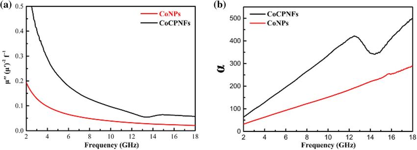
www.nature.com/scientificreports/
Figure 9. (a) Reflection loss (RL) curves for CoNPs, (b) Reflection loss (RL) curves for PCNF, (c) S1, (d) S2
and (e) S3 with different thickness in the frequency range of 2–18 GHz, (f) RL values of Co/PCNF at “matching
thickness” (tm) in 2.00–18.00 GHz.
The reflection loss (RL) curves of CoNPs, PCNF, and Co/PCNF at different thickness in 2.00–18.00 GHz is
sketched in Fig. 9a–f. The reflection loss (RL) of a single materials CoNPs is disappointing, the maximum reflec-
tion loss (RL) value of it is only – 1.60 dB at 18.00 GHz with a thickness of 3.00 mm, as shown in Fig. 9a. For the
sake of contrast, this work also gives the RL value of PCNF (Fig. 9b). Obviously, both PCNFs and CoNPs are
single materials, and their RL values are not ideal, and they cannot be applied solely to the absorption of EM.
Correspondingly, Co/PCNF (Fig. 9c–e) exhibits an excellent microwave absorption property: As the content of
CoNPs increases, the absorbing performance of Co/PCNF shows a trend of first increasing and then decreasing.
As the content of CoNPs increases, the absorbing performance of Co/PCNF shows a trend of first increasing
and then decreasing. The effective absorption bandwidth of S1 in the entire test range is 9.4 GHz (2.6–8.6 GHz,
8.9–12.3 GHz), and the minimum reflection value reaches − 29.4 dB at a thickness of 2.00 mm (as shown in
Fig. 9c). In contrast, the performance of S2 is relatively excellent (as shown in Fig. 9d), the effective absorp-
tion bandwidth in the range of 2–18 GHz reaches 12.5 GHz (8.9–12.3 GHz), and the reflection value reaches
− 29.3 GHz when the absorbing body thickness is 5.21 mm. Among all the samples, the best performance is S3. In
Fig. 9e, when the absorber thickness exceeds 3 mm, the composite materials begin to affect electromagnetic wave
attenuation performance (the RL value is less than − 10 dB, more than 90% attenuation), and maximum reflec-
tion loss (RL) value can reach − 63.69 dB at 5.28 GHz with a thickness of 5.21 mm. Furthermore, as for 5.60 mm
and 6.61 mm absorber, there are two absorption peaks of − 47.60 dB and − 48.30 dB appear around 12.50 GHz
and 14.10 GHz, respectively. At the same time, the effective absorption bandwidth (EABW, RL ≤ − 10.0 dB) of
Co/PCNF is 12.92 GHz (3.18–7.96 GHz and 11.55–18.00 GHz). Thus, the S3 absorber can effectively attenuate
the EM wave in part of the C band and entire Ku band. It’s clear that the maximum reflection loss (RL) value
of Co/PCNF moves to the low frequency band with a decrease in thickness, where the show in Fig. 9f. This
phenomenon can be mainly explained by the theory of quarter-wavelength, which can be expressed by the fol-
lowing equation51,53:
tm = n/4 = nc/ 4fm |µ||ε| (n = 1, 3, 5 . . .) (8)
where c is the velocity of light. When the thickness of the absorber satisfies the quarter-wavelength cancel-
lation model, the phase difference between the incident electromagnetic wave and the reflected electromag-
netic wave isπ, and they will cancel each other on the air-material surface, which is beneficial to the improve-
ment of the absorption performance (as shown in Fig. 10c). This kind of variation tells us that the microwave
absorption properties of Co/PCNF can be regulated by matching the absorber thickness in a frequency range
of 2.00–18.00 GHz. Figure 9d shows that tm calculated by MATLAB can perfectly be matching the RL curve,
indicating that Co/PCNF satisfies the quarter-wavelength formula.
We further evaluate the microwave absorption performance (reflection loss, absorber thickness, and absorp-
tion bandwidth) of Co/PCNF in comparison to those of the same types of Co/C composites ever reported
(Table 2).
Scientific Reports | (2021) 11:2171 | https://doi.org/10.1038/s41598-021-81848-7 10
Vol:.(1234567890)www.nature.com/scientificreports/
Figure 10. The illustration for main microwave attenuation mechanisms. (a) Hopping and migrating of free
electrons under an electromagnetic field, (b) Interface polarization at the interface of CoNPs and PCNF, (c) EM
transmission path.
Maximum RL
Absorber thickness Absorption bandwidth
Sample Value (dB) Matching thickness (mm) Matching frequency (GHz) (RL ≤ − 10 dB) (mm) (RL ≤ − 10 dB) (GHz) Refs.
5
Co/CNFs − 63.10 1.60 12.80 1.10–5.00 14.30 (3.70–18.00)
6
Co-CNTs − 39.32 3.00 15.71 3.00–4.00 5.70 (11.80–17.50)
7
Co/C nanoparticles − 43.40 2.30 16.80 1.00–4.00 14.00 (4.00–18.00)
8
Co/C nanocomposites − 35.30 2.50 5.80 1.00–5.00 13.70 (3.70–17.40)
9
Co/Graphene − 47.50 2.00 11.90 1.00–5.00 11.20 (2.80–14.00)
10
Co/C-800 − 32.40 2.00 9.60 1.00–5.00 13.50 (4.50–18.00)
34
Co/Porous carbon − 40.00 5.00 4.20 1.50–5.00 12.80 (3.70–16.50)
Co/CPNFs − 63.69 5.21 5.28 1.00–6.61 12.92 (3.2–018.00) Herein
Table 2. Microwave absorption performance of various typical Co-based composites.
Scientific Reports | (2021) 11:2171 | https://doi.org/10.1038/s41598-021-81848-7 11
Vol.:(0123456789)www.nature.com/scientificreports/
Ultimately, the dielectric loss a part of excellent microwave absorption performance of Co/PCNF comes of
different resistivity of carbon materials and magnetic nanoparticles, which leads to electrons asymmetry distribu-
tion, then a large amount of space charges is accumulated in the interface, eventually leading to the occurrence
of interface polarization51,52,55. Structurally, the stronger interface polarization existed in the carbon-porous
interface and the CoNPs-porous interface by the porous is abundant in Co/PCNF. In addition, when the EM wave
enters the absorber, the unique 3D cross-linked network structure can provide multiple reflections. Moreover,
benefited from the relatively low graphitization degree, Co/PCNF obtained excellent matching impedance, which
can reduce the reflection of the material surface to EM wave and will allow more microwave can be transmitted
into the materials. Above all, Dielectric loss is mainly caused by conductance loss and interfacial polarization.
Natural resonance, exchange resonance, and eddy current loss provide magnetic loss mechanism. As a result, it
is that we can design the impedance match and interfacial polarization of absorber by introducing the porous
nanostructure, which plays a positive role in microwave absorption. Thus, due to the above reasons, the Co/
PCNF has potential to be a microwave absorbing material with superior attenuation ability for the incident
electromagnetic waves.
Conclusions
In general, we used high energy ion beam evaporation (HEIBE) to prepare the core–shell structure cobalt nano-
particles (CoNPs), and the Co/C porous nanofibers (Co/CPNFs) with low graphitization degree obtained by
the electrospinning method and following sintering process with sintering temperature of 800 ℃. Experimental
results show that by 3D-network structure, porous structure and magnetic nanoparticles doping, the imped-
ance matching, dielectric loss, magnetic loss, and high attenuation constant can be optimized, which leads to
Co/CPNFs have excellent microwave absorption properties. Beyond that, the porous and Co nanoparticles also
can introduce a new interface, defects to enhance interfacial polarization. The Co/CPNFs exhibit the maximum
reflection loss (RL) reaches − 63.69 dB at 5.28 GHz with a thickness of 5.21 mm and the absorption bandwidth
(RL ≤ − 10.0 dB) is 12.92 GHz (3.18–7.96 GHz and 11.55–18.00 GHz). These results suggest that Co/C porous
nanofibers are considered to be a suitable candidate for the manufacture of lightweight and high-efficiency
microwave absorbing materials. Also, the facile synthesis of Co/CPNFs provide an easy and implemental method
for large scale preparation of high-performance microwave absorption materials.
Received: 5 October 2020; Accepted: 7 January 2021
References
1. Zhang, Y. et al. Broadband and tunable high-performance microwave absorption of an ultralight and highly compressible graphene
foam. Adv. Mater. 27, 2049–2053 (2015).
2. Sun, H. et al. Cross-stacking aligned carbon-nanotube films to tune microwave absorption frequencies and increase absorption
intensities. Adv. Mater. 26, 8120–8125 (2014).
3. Li, X. H. et al. One-pot synthesis of C oFe2O4/graphene oxide hybrids and their conversion into FeCo/graphene hybrids for light-
weight and highly efficient microwave absorber. J. Mater. Chem. A 3, 5535–5546 (2015).
4. Xiang, J. et al. Magnetic carbon nanofibers containing uniformly dispersed Fe/Co/Ni nanoparticles as stable and high-performance
electromagnetic wave absorbers. J. Mater. Chem. A 2, 16905–16914 (2014).
5. Bayrakdar, H. Fabrication, magnetic and microwave absorbing properties of Ba2Co2Cr2Fe12O22 hexagonal ferrites. J. Alloys Compd.
674, 185–188 (2016).
6. Lin, H. Y., Zhu, H., Guo, H. F. & Yu, L. F. Microwave-absorbing properties of Co-filled carbon nanotubes. Mater. Res. Bull. 43,
2697–2702 (2008).
7. Liu, T., Xie, X. B., Pang, Y. & Kobayashi, S. Co/C nanoparticles with low graphitization degree: a high performance microwave-
absorbing material. J. Mater. Chem. C 4, 1727–1735 (2016).
8. Lu, Y. Y. et al. MOF-derived porous Co/C nanocomposites with excellent electromagnetic wave absorption properties. ACS Appl.
Mater. Interfaces 7, 13604–13611 (2015).
9. Pan, G. H., Zhu, J., Ma, S. L., Sun, G. B. & Yang, X. J. Enhancing the electromagnetic performance of co through the phase-con-
trolled synthesis of hexagonal and cubic co nanocrystals grown on graphene. ACS Appl. Mater. Interfaces 5, 12716–12724 (2013).
10. Qiang, R. et al. Electromagnetic functionalized Co/C composites by in situ pyrolysis of metal–organic frameworks (ZIF-67). J.
Alloys Compd. 681, 384–393 (2016).
11. Yang, S. L. et al. Nitrogen, phosphorus, and sulfur co-doped hollow carbon shell as superior metal-free catalyst for selective oxida-
tion of aromatic alkanes. Angew. Chem. Int. Ed. 55, 4016–4020 (2016).
12. Chen, Y. Z. et al. From bimetallic metal–organic framework to porous carbon: high surface area and multicomponent active
dopants for excellent electrocatalysis. Adv. Mater. 27, 5010–5016 (2015).
13. Song, B. et al. Molecular level study of graphene networks functionalized with phenylenediamine monomers for supercapacitor
electrodes. Chem. Mater. 28, 9110–9121 (2016).
14. Wang, L. et al. Synthesis and microwave absorption enhancement of graphene@Fe3O4@SiO2@NiO nanosheet hierarchical struc-
tures. Nanoscale. 6, 3157–3164 (2014).
15. Ding, D. et al. Rational design of core–shell Co@C microspheres for high-performance microwave absorption. Carbon 111, 722–732
(2017).
16. Wang, F. Y. et al. Preparation of mono-dispersed, high energy release, core/shell structure Al nanopowders and their application
in HTPB propellant as combustion enhancers. Sci. Rep. 7, 1–4 (2017).
17. Wang, F. Y. et al. Microwave absorption properties of 3D cross-linked Fe/C porous nanofibers prepared by electrospinning. Carbon
134, 264–273 (2018).
18. Rajendran, M. et al. Magnetic properties of nanocrystalline CoFe2O4 powders prepared at room temperature: variation with
crystallite size. J. Magn. Magn. Mater. 232, 71–83 (2001).
19. Lu, B. G. et al. Direct preparation of carbon nanotubes and nanobelts from polymer. Nanoscale 3, 2145–2149 (2011).
20. Graf, D. et al. Spatially resolved raman spectroscopy of single- and few-layer graphene. Nano Lett. 7, 238–242 (2007).
21. Lv, H. L. et al. Achieving tunable electromagnetic absorber via graphene/carbon sphere composites. Carbon 110, 130–137 (2016).
22. Lv, R. T. et al. Single-crystalline permalloy nanowires in carbon nanotubes: enhanced encapsulation and magnetization. J. Phys.
Chem. C 111, 11475–11479 (2007).
Scientific Reports | (2021) 11:2171 | https://doi.org/10.1038/s41598-021-81848-7 12
Vol:.(1234567890)www.nature.com/scientificreports/
23. Fang, Y. H. et al. Preparation and enhanced microwave absorption properties of Ni–Co attached single-walled carbon nanotubes
and CoFe2O4 nanocomposites. J. Appl. Phys. 121, 224301 (2017).
24. Wang, C. et al. Controlled synthesis of hierarchical nickel and morphology-dependent electromagnetic properties. J. Phys. Chem.
C 114, 3196–3203 (2010).
25. Liu, P. B., Huang, Y. & Zhang, X. Preparation and excellent microwave absorption properties of ferromagnetic graphene/poly(3,
4-ethylenedioxythiophene)/CoFe2O4 nanocomposites. Powder Technol. 276, 112–117 (2015).
26. Ni, Q. Q., Zhu, Y. F., Yu, L. J. & Fu, Y. Q. One-dimensional carbon nanotube@barium titanate@polyaniline multiheterostructures
for microwave absorbing application. Nanoscale Res. Lett. 10, 1–8 (2015).
27. Wu, H., Wang, L. D., Wu, H. J. & Lian, Q. Synthesis and significantly enhanced microwave absorption properties of hematite
dendrites/polyaniline nanocomposite. Appl. Phys. A Mater. Sci. Process. 115, 1299–1307 (2014).
28. Liu, X. G., Geng, D. Y., Meng, H., Shang, P. J. & Zhang, Z. D. Microwave-absorption properties of ZnO-coated iron nanocapsules.
Appl. Phys. Lett. 92, 173117 (2008).
29. Yu, L. M., Li, B., Sheng, L. M., An, K. & Zhao, X. L. The microwave absorbing properties of SmCo attached single wall carbon
nanotube/epoxy composites. J. Alloys Compd. 575, 123–127 (2013).
30. Chen, Y. J., Gao, P., Wang, R. X. & Zhu, C. L. High-frequency absorption of the hybrid composites with spindle-like F e3O4 nano-
particles and multiwalled carbon nanotubes. J. Phys. Chem. C 113(23), 10061–10064 (2009).
31. Deng, L. J. & Han, M. G. Microwave absorbing performances of multiwalled carbon nanotube composites with negative perme-
ability. Appl. Phys. Lett. 91(2), 023119 (2007).
32. Zhen, L., Jiang, J. T., Shao, W. Z. & Xu, C. Y. Resonance-antiresonance electromagnetic behavior in a disordered dielectric com-
posite. Appl. Phys. Lett. 90(14), 142907 (2007).
33. Wang, Y. et al. Synthesis of polyaniline nanorods and Fe3O4 microspheres on graphene nanosheets and enhanced microwave
absorption performances. Mater. Chem. Phys. 209, 23–30 (2018).
34. Xi, L., Wang, Z., Zuo, Y. & Shi, X. The enhanced microwave absorption property of CoFe(2)O(4) nanoparticles coated with a Co(3)
Fe(7)-Co nanoshell by thermal reduction. Nanotechnology 22, 045707 (2011).
35. Tang, X. T. et al. Microwave absorption performance enhanced by high-crystalline graphene and BaFe12O19 nanocomposites. J.
Appl. Phys. 119, 204301 (2016).
36. Adohi, B. J. P., Bychanok, D., Haidar, B. & Brosseau, C. Microwave and mechanical properties of quartz/graphene-based polymer
nanocomposites. Appl. Phys. Lett. 102, 753 (2013).
37. Youssef, J. B. & Brosseau, C. Magnetization damping in two-component metal oxide micropowder and nanopowder compacts by
broadband ferromagnetic resonance measurements. Phys. Rev. B 74, 4070–4079 (2006).
38. Crisan O, Greneche JM, Labaye Y, Berger L, Crisan AD, Angelakeris M, et al. Magnetic Properties of Nanostructured Materials
(2005).
39. Wu, M. Z. et al. Microwave magnetic properties of Co-50/(SiO2)(50) nanoparticles. Appl. Phys. Lett. 80, 4404–4406 (2002).
40. Yin, Y. C., Liu, X. F., Wei, X. J., Yu, R. H. & Shui, J. L. Porous CNTs/Co composite derived from zeolitic imidazolate framework: a
lightweight, ultrathin, and highly efficient electromagnetic wave absorber. ACS Appl. Mater. Interfaces 8, 34686–34698 (2016).
41. Tong, G. X. et al. Enhanced electromagnetic characteristics of carbon nanotubes/carbonyl iron powders complex absorbers in
2–18 GHz ranges. J. Alloys Compd. 509, 451–456 (2011).
42. Brosseau, C., Ben Youssef, J., Talbot, P. & Konn, A. M. Electromagnetic and magnetic properties of multicomponent metal oxides
heterostructures: nanometer versus micrometer-sized particles. J. Appl. Phys. 93, 9243–9256 (2003).
43. Xiong, L. L., Yu, M., Liu, J. H., Li, S. M. & Xue, B. Preparation and evaluation of the microwave absorption properties of template-
free graphene foam-supported Ni nanoparticles. RSC Adv. 7, 14733–14741 (2017).
44. Wang, H. et al. Broadband microwave absorption of CoNi@C nanocapsules enhanced by dual dielectric relaxation and multiple
magnetic resonances. Appl. Phys. Lett. 102, 223113 (2013).
45. Deng, L. J., Zhou, P. H., Xie, J. L. & Zhang, L. Characterization and microwave resonance in nanocrystalline FeCoNi flake composite.
J. Appl. Phys. 101, 103916 (2007).
46. Wen, F. S., Zhang, F. & Liu, Z. Y. Investigation on microwave absorption properties for multiwalled carbon nanotubes/Fe/Co/Ni
nanopowders as lightweight absorbers. J. Phys. Chem. C 115, 14025–14030 (2011).
47. Li, D. et al. Enhanced microwave absorption properties in C band of Ni/C porous nanofibers prepared by electrospinning. J. Alloys
Compd. 800, 294–304 (2019).
48. Zhuo, R. F. et al. Multistep synthesis, growth mechanism, optical, and microwave absorption properties of ZnO dendritic nano-
structures. J. Phys. Chem. C 112, 11767–11775 (2008).
49. Lu, M. M. et al. Multiscale assembly of grape-like ferroferric oxide and carbon nanotubes: a smart absorber prototype varying
temperature to tune intensities. ACS Appl. Mater. Interfaces 7, 19408–19415 (2015).
50. Wang, L. X. et al. Efficient ferrite/Co/porous carbon microwave absorbing material based on ferrite@metal-organic framework.
Chem. Eng. J. 326, 945–955 (2017).
51. Zhao, B., Fan, B., Shao, G., Zhao, W. & Zhang, R. Facile synthesis of novel heterostructure based on SnO2 nanorods grown on
submicron ni walnut with tunable electromagnetic wave absorption capabilities. ACS Appl. Mater. Interfaces 7, 18815–18823 (2015).
52. Guo, J. et al. One-step seeding growth of controllable Ag@Ni core–shell nanoparticles on skin collagen fiber with introduction of
plant tannin and their application in high-performance microwave absorption. J. Mater. Chem. 22, 11933 (2012).
53. Pan, J. et al. Shape anisotropic F e3O4 nanotubes for efficient microwave absorption. Nano Res. 13(3), 621–629 (2020).
54. Li, T. et al. Multiaxial electrospun generation of hollow graphene aerogel spheres for broadband high-performance microwave
absorption. Nano Res. 13(2), 477–484 (2020).
55. Song, L. et al. Transformation between nanosheets and nanowires structure in M nO2 upon providing C o2+ ions and applications
for microwave absorption. Nano Res. 13(1), 95–104 (2020).
56. Nie, R. et al. A sandwich N-doped graphene/Co3O4 hybrid: an efficient catalyst for selective oxidation of olefins and alcohols. J.
Mater. Chem. A 1(32), 9037–9045 (2013).
57. Liu, S. et al. Dual modulation via electrochemical reduction activiation on electrocatalysts for enhanced oxygen evolution reaction.
ACS Energy Lett. 4(2), 423–429 (2019).
Acknowledgements
The research was financially supported by the National Natural Science Foundation of China (Grant Nos.
51665003, 51761001), Lanzhou Municipal science and technology project (Grant No. 2016-3-44) , Science and
Technology Industrialization Project of Gansu Academy of Sciences (Grant No. 2017CY-12,2018CY-09) , Gansu
Academy of Sciences Applied Research and Development Project (Grant No. 2018JK-12), the Natural Science
Foundation for Young Scientists of Gansu Province, China (Grant No.1506RJYA220).
Author contributions
Y.Z.: Conceptualization, Data curation, Formal analysis, Investigation, Methodology, Software, Writing-Original
draft preparation. Z.W.: Conceptualization, Funding acquisition, Methodology, Writing-Reviewing and Editing,
Scientific Reports | (2021) 11:2171 | https://doi.org/10.1038/s41598-021-81848-7 13
Vol.:(0123456789)www.nature.com/scientificreports/
Supervision. S.W., Y.Z., P.Y.: Conceptualization, Formal analysis, Funding acquisition, Investigation, Writing-
Reviewing and Editing. B.Z., J.F., D.L., F.W., R.Z., and J.T.; Data curation, Formal analysis.
Competing interests
The authors declare no competing interests.
Additional information
Correspondence and requests for materials should be addressed to Z.G.W.
Reprints and permissions information is available at www.nature.com/reprints.
Publisher’s note Springer Nature remains neutral with regard to jurisdictional claims in published maps and
institutional affiliations.
Open Access This article is licensed under a Creative Commons Attribution 4.0 International
License, which permits use, sharing, adaptation, distribution and reproduction in any medium or
format, as long as you give appropriate credit to the original author(s) and the source, provide a link to the
Creative Commons licence, and indicate if changes were made. The images or other third party material in this
article are included in the article’s Creative Commons licence, unless indicated otherwise in a credit line to the
material. If material is not included in the article’s Creative Commons licence and your intended use is not
permitted by statutory regulation or exceeds the permitted use, you will need to obtain permission directly from
the copyright holder. To view a copy of this licence, visit http://creativecommons.org/licenses/by/4.0/.
© The Author(s) 2021
Scientific Reports | (2021) 11:2171 | https://doi.org/10.1038/s41598-021-81848-7 14
Vol:.(1234567890)You can also read