A New Chaotic Mixer Design Based on the Delta Robot and Its Experimental Studies
←
→
Page content transcription
If your browser does not render page correctly, please read the page content below
Hindawi
Mathematical Problems in Engineering
Volume 2021, Article ID 6615856, 15 pages
https://doi.org/10.1155/2021/6615856

Research Article
A New Chaotic Mixer Design Based on the Delta Robot and Its
Experimental Studies

 Onur Kalayci ,1 Ihsan Pehlivan,2 Akif Akgul,3 Selcuk Coskun,4 and Ersin Kurt5
 1
 Faculty of Technology, Department of Mechatronics Engineering, Sakarya University of Applied Sciences, Adapazari,
 Sakarya 54050, Turkey
 2
 Faculty of Technology, Department of Electric-Electronics Engineering, Sakarya University of Applied Sciences, Adapazari,
 Sakarya 54050, Turkey
 3
 Faculty of Engineering, Department of Computer Engineering, Hitit University, Corum 19030, Turkey
 4
 IMKB Sakarya Vocational and Technical Anatolian High School, Adapazari, Sakarya 54050, Turkey
 5
 Faculty of Electric-Electronics Engineering Afyon Kocatepe University, Afyon 03200, Turkey

 Correspondence should be addressed to Onur Kalayci; okalayci67@gmail.com

 Received 20 December 2020; Revised 23 January 2021; Accepted 7 March 2021; Published 23 March 2021

 Academic Editor: Zenghui Wang

 Copyright © 2021 Onur Kalayci et al. This is an open access article distributed under the Creative Commons Attribution License,
 which permits unrestricted use, distribution, and reproduction in any medium, provided the original work is properly cited.
 In this study, a new chaotic mixer based on the Delta robot was designed and produced which had been controlled with Arduino
 Uno card and MATLAB. First of all, chaotic mixing systems with different dynamic properties were chosen for the chaotic mixing
 process. Then, by solving the chaotic systems selected in the MATLAB with the Runge Kutta 45 (RK45) numerical solution
 algorithm, the results in the integer format were obtained. The obtained chaotic time-series results were transformed into 3-
 dimensional position information for the servomotors used in the mixer with the algorithm developed in MATLAB. The su-
 pervision was provided to ensure that the newly designed chaotic mixer was pacing chaotically in x, y, and z coordinates by
 transferring the chaotic position information to the Arduino Uno R3 card via USB 2.0. With the software developed in MATLAB,
 the performances of 7 diversified chaotic systems’ trajectories and circular motion trajectories were compared over the numerical
 simulation orbital distribution ratio (ODR). In the final stage, in a solid-liquid mixture type, at the selected constant mixing time,
 experimental studies were performed where homogeneity and orbital distribution ratio (ODR) parameters were compared by
 using 7 diversified chaotic systems. The designed and produced chaotic mixer can also be used in experimental studies of certain
 liquid-liquid mixture types. It is thought that this prototype presented in the article will serve the aim of developing new chaotic
 mixer systems and algorithms to derive more homogeneous mixtures in a shorter time.

1. Introduction more widely used mixers and designing more efficient
 mixers are of great importance for the companies that
Combining at least two different substances is called mixing, manufacture these machines or the ones that use these
and the devices that carry out this process are called mixers. machines [1].
The substances required to be mixed are in the form of solid, Factors affecting mixing are given in the following:
liquid, gas, or varieties of those. The most emphasized pa- mixing temperature, mixing duration, agitator type, and
rameters in mixing are the duration and homogeneity of the agitator motor speed. Mixer types used in industries are
mixing process. The higher the homogeneity of the mixture given in the following: turbine-type stirrer, propeller mixer,
and the shorter the working time of the mixer, the higher the flat-blade turbine type, kneader, dry mixer, and planetary
performance of the mixer is [1]. mixer [1].
 Mixers are used in several areas such as at homes, in Professors Banhero and Bodger [2] researched mixing
kitchens, in bakeries with dough kneading machines, in theory of matter states in solid, liquid, and gaseous in their
factories, and in construction zones. The development of study. Vauck and Müller [3] studied on the degree of the
2 Mathematical Problems in Engineering

mixture, mixing duration, mixing methods, and standard- in MATLAB to the angle values of the Delta robot arms were
ization of mixers. Henzler and Eignung [4] observed the explained. In the third part of the study, the performances of
homogeneity of the continuous mixers in their study. Ilten the orbits and circular motion trajectories of 7 different
examined mixers, mixing methods, mixing events, and chaotic systems are evaluated by comparing them with the
mixer power calculations in his thesis study [5]. Can, in his numerical simulation orbital distribution ratios obtained in
thesis study, modelled the homogeneous mixing of two MATLAB. In the fourth part of the study, experimental
different fluids with a disc axially moving back and forth in a studies have been carried out for the Sprott_A chaotic
cylindrical container and rotating at a certain speed around system with the highest orbital distribution ratio and the
its axis [6]. Lu–Chen chaotic system with the lowest orbital distribution
 Inspiring studies such as machining sequences optimi- ratio and the movement of the mixer propeller in a circular
zation [7], automotive testing [8], navigation control and and fixed position.
stability investigation of a mobile robot [9], and complex
trajectories of the omniwheel robot in machine [10] in 2. Materials and Methods
automotive and robotic fields have been carried on in recent
years. 2.1. Chaotic Systems. Chaos is a branch of science that helps
 In 1988, Angeles designed the Delta robot at the Lau- explain nonlinear events, expressed as the order of disorder.
sanne Federal Polytechnic Institute (EPFL). He designed this Chaos is not a random event, as it has its own internal order
robot to perform translational movements in the 3D space in addition to complex behaviors. Chaos can be expressed as
[11]. In 2004, Zsombor-Murray wrote a software that could the most complex known state of dynamical systems. Chaos
analytically model the forward and inverse kinematics of the focuses on the interrelationship of events that occur from
delta robot, the intersection points of a central fixed circle, delicate differences within randomly thought situations.
and a sphere with a central motion and make these calcu- Chaos science is a branch of science that tries to understand
lations on a computer [12]. Şanlıtürk designed the Delta the events in real life that are thought to behave randomly
robot which can do the visual operation, and he searched its such as the movement of clouds, the cigarette smoke
performance features in his thesis study [13]. Qiaoling et al., movement, bubbling river movements, and the movement
in their study, suggested the optimal design method of a of water flowing from the tap [34, 35].
Linear Delta robot (LDR) to obtain the proposed rectangular Chaos can be briefly expressed as dynamical systems that
working area (PCDW) [14]. Xin-Jun et al. presented a new are hypersensitive to initial and input conditions [34, 36].
design method by considering the desired working area and Due to this sensitivity of chaotic systems to the initial and
the swing range in the spherical joints of a Delta robot in input conditions, small changes in these values cause the
their study [15]. output of the system to change. For this reason, although
 There are many scientific studies on chaotic systems, chaotic structures are deterministic systems, the behavior of
chaotic signals, and engineering applications in the literature the system can be predicted only for a short time. During the
[16–27]. One of the application areas where chaotic signals following iterations, the behavior of chaotic systems be-
are used has been chaos-based mixers. Chau et al. used a comes unpredictable [34, 35]. Due to these characteristics,
floating DC engine as a mixer in their study. The speed of the the number of chaotic system studies conducted in scientific
DC motor is chaotically adjusted, and the mixing is done and industrial areas such as cryptology, control, image
with time delay [28]. Ye and Chau used a DC engine as a processing, communication, and artificial neural networks is
mixer in their study. The speed of the DC engine was increasing rapidly [34, 37, 38].
chaotically adjusted by the unstable method [29]. Ye and Chaotic systems can be studied in two groups as discrete-
Chau used a time-delayed floating DC engine as a mixer in time and continuous-time chaotic systems. Discrete-time
their study [30]. In all three studies, the results of chaotic chaotic systems are usually unidimensional or bidimen-
mixing were compared with the results of mixing at constant sional which means they can consist of one or two equations.
speed. The acid-base neutralization reaction was evaluated in On the contrary, continuous-time chaotic systems are at
these experiments [28–30]. Murtadha et al. studied on the least tridimensional which means they contain at least three
chaotic control of a liquid mixer. In this study, the water-salt equations [34, 39, 40].
mixture was stirred for 30 seconds. The results were eval-
uated by making concentrated measurements [31]. In Zhang
and Chen’s study, the vessel containing the mixture was 2.1.1. Discrete-Time Chaotic Systems. Discrete-time chaotic
fixed to a plate rotated by a DC motor by keeping the blades systems are formed by the iteration of a proper nonlinear
of the mixer fixed. The motor speed was chaotically adjusted function; in other words, they are the chaotic systems with
by using the Chua circuit. In the experiment, the water-sugar the feedback property. Discrete-time chaotic systems can be
mixture was evaluated [32]. Kavur et al. designed a chaotic used directly in desired applications in digital environments
system-based Delta robot in their study to mix graphene without the need for discretization algorithms such as
nanoplatelets [33]. continuous-time chaotic systems [41].
 In the second part of the study, the design of the delta There are many unidimensional and bidimensional
robot-based chaotic mixer and the conversion calculations discrete-time chaotic systems in the literature [34, 38, 40].
of the instantaneous signal amplitude values of the chaotic Logistic Map [42], Cubic Map [43], Sine Map [44], and Tent
time series (x, y, z) produced by the new software developed Map [45] chaotic systems can be shown as examples of

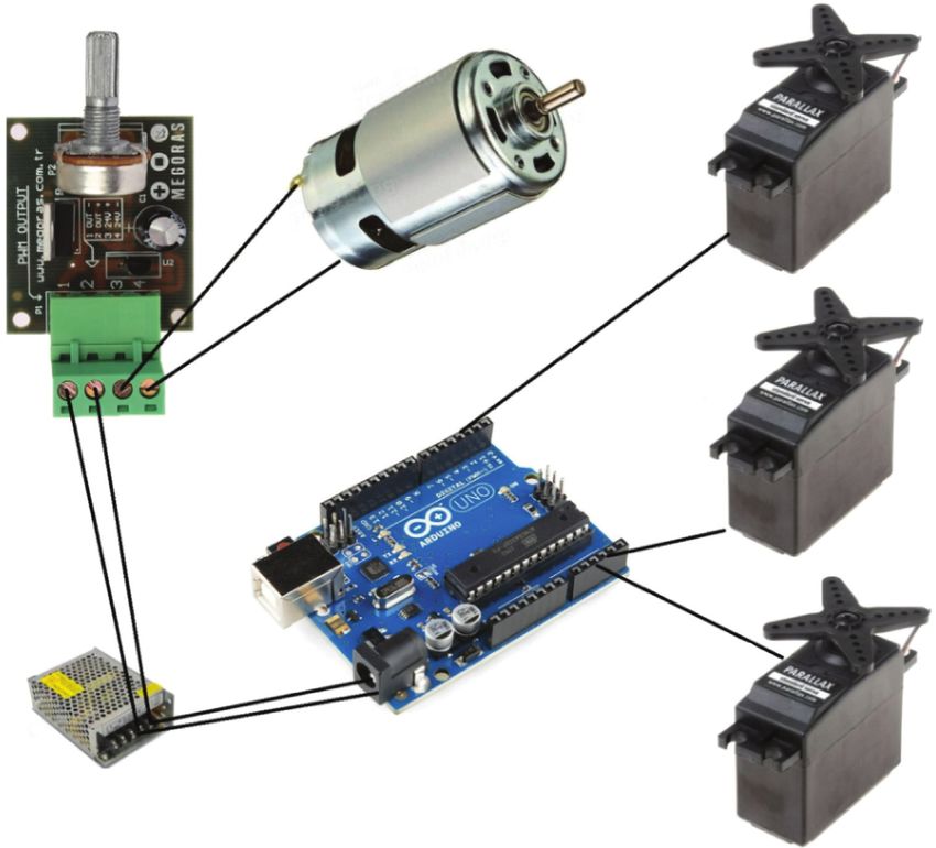
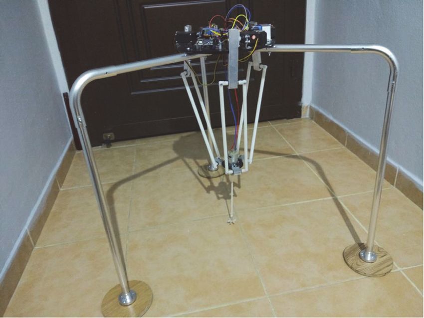
Mathematical Problems in Engineering 3

unidimensional discrete-time chaotic systems. Henon Map and mobile planes constantly remain parallel. Therefore, the
[46], Lozi Map [47], Burgers’ Map [48], Discrete Predator- Delta robot moves as 3 axes [64, 65].
Prey Map [49], and Arnold’s Cat Map [50] can be shown as
examples of bidimensional discrete-time chaotic systems
[41]. 2.3. The Design of the Chaotic Delta Robot. Servomotors
 with 5 VDC and 10 Nm torque were preferred for the
 movement of Delta robot parallel arms. The Arduino Uno
2.1.2. Continuous-Time Chaotic Systems. R3 control card was chosen for the control of the designed
Continuous-time chaotic systems (CTCS) are generally delta robot. A 12V DC 12 rpm motor was used for the mixer
expressed by ordinary differential equations. N continuous- motor connected to the Delta robot. PWM (Pulse Width
time first-order ordinary differential equations with I � 1, 2, Modulation) based DC motor speed control was designed
3, ..., n can be like the following equation [34, 51]: and used for speed control of the mixer motor. Mechanical
 parts were made of the lightweight and durable aluminium
 dx(i) material. All components related to the design of the Delta
 � f1 x(i) , x(i+1) , . . . , x(n)
 dt robot-based chaotic mixer can generally be seen in Figure 2.
 A standard Arduino software package, which enables the
 dx(i+1) communication between MATLAB and Arduino, can be
 � f2 x(i) , x(i+1) , . . . , x(n) downloaded and installed from MATLAB’s website. With
 dt . (1) the help of the Arduino software package, the chaotic lo-
 cation information produced by the algorithm developed in
 ⋮ MATLAB is sent to the Arduino Uno R3 card on the Delta
 robot. The DC motor can be operated at the desired speed
 dx(n) and direction with the potentiometer on the PWM DC
 � fn x(i) , x(i+1) , . . . , x(n) motor control card at the same time. The circuit connection
 dt
 diagram of the Delta robot-based chaotic mixer is shown in
 Ordinary differential equations can be in the vector form Figure 3.
as in equation (2) if the above expressions are edited: The designed and implemented Delta robot-based
 dx(t) chaotic mixer is shown in Figure 4.
 � F[x(t)],
 dt (2)
 x t 0 � x0 . 2.4. Chaotic Mixer Software. The block diagram of Delta
 robot-based chaotic mixer software and components is
 Given in the equation, x is an n-dimensional vector, shown in Figure 5.
while x0 means the initial state vector and t means the time. As shown in the block diagram in Figure 5, the Arduino
Discrete-time chaotic systems are expressed by unidimen- software package downloaded from the MATLAB web
sional nonlinear simple equations, whereas continuous-time enabled the communication between the Arduino Uno R3
chaotic systems are at least 3-dimensional. So, the expression card which was connected to servo motors and MATLAB
n must be at least three [34, 51]. programme. In the MATLAB platform, an interface was
 In the literature, Zhang et al. [52], Precup et al. [53], Sheu developed in which chaotic system, numerical solution it-
et al. [54], Kuetche et al. [55], Sundarapandian [56], Chen eration number, and servo motor speeds could be selected
and Ueta [57], Vembarasan and Balasubramaniam [58], and and changed. One of 7 different chaotic systems can be
Rucklidge [59, 60] chaotic systems can be shown as an chosen through the interface. x, y, and z chaotic time series
example of continuous-time chaotic systems; Arneodo [61], data are obtained by solving the chaotic system selected from
Hindmarsh-Rose [62], and Spring [63] chaotic systems can the developed interface with the method of the RK45 nu-
be shown as an example of hyperchaotic systems [35]. merical solution in MATLAB.

2.2. Delta Robot. Recently, the demand for high-speed pick- 2.4.1. Conversion of Instant Signal Amplitude Values to Robot
up and packaging systems has been increasing in the pro- Angle Values. With the new software developed in the
duction areas of industry. Nowadays, parallel manipulators MATLAB platform, maximum signal amplitude value
have become more significant as parallel manipulators are (Max_SAV) and minimum signal amplitude value (Min_-
more robust and have more precise positioning due to high- SAV) are determined by generating instant signal amplitude
precision motion performance is required from many me- values (I_SAV) of the chaotic time series (x, y, z).
chanical systems. The delta robot, one of the parallel ma- Max_SAV is linearly scaled to correspond to the max-
nipulators in Figure 1, can move in the required x, y, and z imum mobility angle value of the robot arms (Max_MAV),
coordinates of the working area with 3 motors mounted on a while Min_SAV is linearly scaled to correspond to the
fixed plate and the plates attached to each. The motors on the minimum mobility angle value of the robot arms (Min_-
fixed plate are placed symmetrically, and each motor with MAV) and converted to chaotic position information (robot
the connected arm are controlled. For this reason, stationary angle values (R_AV)).
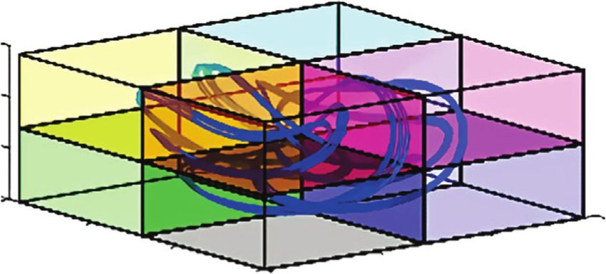
4 Mathematical Problems in Engineering

 Q3 Absolute coordinate system
 θ3 –world coordinates
 X Q1
 O
 θ2 Y θ1
 Z
 Q2
 Coordinate system of the
 machine
 –angles of drives

 Relative coordinate system
 –relative coordinates
 R3
 X (towards the platform)
 Y
 R
 Z R1
 R2

 Figure 1: Delta robot [64].

 Data I/O ARDUINO

 MATLAB

 USB

 Delta robot Motor control

 Figure 2: The components related to the design of Delta robot stages.

 The variants and abbreviations used in the algorithm that (c) By dividing Max_MAV (e.g., 144°) entered through
converts the I_SAV (x, y, z) of chaotic time series to R_AV the interface into PP_SAV, the angle value per unit
by linear scaling are shown in Table 1. amplitude (PUA_AV) is calculated as in the fol-
 Max_MAV and Min_MAV can be entered with the lowing equation:
interface in the program. The robot arms of the newly Max MAV
designed delta robot-based chaotic mixer can move up to PUA AV � . (4)
 PP SAV
144° on each axis (x, y, z) due to their mechanical properties.
Therefore, Max_MAV and Min_MAV were, respectively, (d) The result found by subtracting Min_SAVs from the
entered as 0° and 144° via the interface. chaotic I_SAV is multiplied by PUA_AV to obtain
 The technical details of the algorithm that converts the required robot angle values (R_AV) as in the
I_SAV to linear scale R_AV during the operation of the following equation:
mixer system are as follows:
 R AV � (I SAV − Min SAV)x PUA AV. (5)
 (a) Min_SAV and Max_SAV are determined for each of
 the chaotic time series signals (x, y, z)
 Examples of algorithms that convert I_SAV on X-axis,
 (b) By substracting Min_SAV from Max_SAV, peak-to- Y-axis, and Z-axis to linear scale R_AV during the operation
 peak signal amplitude value (PP_SAV) is found as in of the mixer system are shown in Figures 6–8.
 the following equation: The mixer propeller connected to the parallel arms of the
 Delta robot moves in the 3-dimensional chaotic positions of
 PP SAV � Max SAV − Min SAV. (3)
 the selected system, as shown in Figure 9.

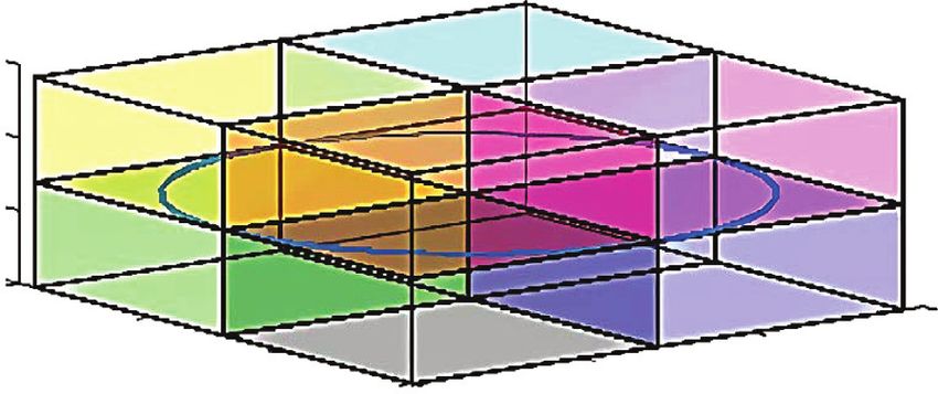
Mathematical Problems in Engineering 5

 PWM DC motor
 speed controller DC motor for mixer Servo motor
 Z-axis

 Servo motor
 Y-axis

 Servo motor
 X-axis

 DC 12V
 power supply

 Figure 3: The circuit connection diagram of the delta robot-based chaotic mixer.

 chaotic system trajectory passes through any of the regions
 in Figure 8, the counter for that zone within the software is
 incremented by one. This operation is repeated as the
 amount of numerical solution iterations’ numbers entered
 through the interface. Since the Max_MAV and Min_MAV
 are entered as 0° and 144°, respectively, the position angle
 values of the chaotic propeller mixer in 8 different regions
 have become as in Table 2.
 When the numerical solution iteration number chosen
 entered through the interface for the chosen chaotic system
 is completed, the number and percentage of the trajectory
 existence in each region are printed on the screen with the
 software. Sample tables belonging to the percentages of the
 chaotic system trajectories’ presence in each region have
 been shown in Section 3.2. Also, the percentages of the
 chaotic system’s trajectories presence in each region were
 used to calculate the orbital distribution rate (ODR) in
 Figure 4: Designed delta robot-based chaotic mixer.
 Section 2.4.3.

2.4.2. Mixer Propeller’s Motion Zones in the Phase Space.
The orbital distribution rate (ODR) is calculated by dividing 2.4.3. Calculation of the Orbital Distribution Rate. To
the three-dimensional phase space into 8 equal regions compare the orbital distribution performance of chaotic
where the chaotic propeller mixer will be travelling. The area systems, it was intended to calculate the uniformity degree of
where the chaotic mixer propeller travels is divided into 8 the orbital distribution ratio (ODR) with great accuracy by
equal zones in the cubic form, as shown in Figure 10. using the trajectory percentages in each of the 8 different
 Within the software, the counters that will count the zones.
number of points in which the chosen chaotic system tra- Equation 6 was used for the calculation of the orbital
jectory passes through 8 zones are reset. When the selected distribution rate (ODR):
6 Mathematical Problems in Engineering

 (i) MATLAB (i) Chaotic signal
 (ii) MATLAB to Arduino ranges to servo (i) Servo motor drivers
 package program motor rotation
 angle (0°–144°) (ii) Servo motors

 (ii) Arduino controller

 Interface Arduino Servo
 programme controller motors

 Figure 5: Block diagram of the Delta robot-based chaotic mixer.

Table 1: Variants and abbreviations used in the algorithm that converts I_SAV of chaotic time series to (x, y, z) to R_AV by scaling linearly.
Variants Abbreviations
Maximum mobility angle value of robot arms Max_MAV
Minimum mobility angle value of robot arms Min_MAV
Instant signal amplitude value I_SAV
Minimum signal amplitude value Min_SAV
Maximum signal amplitude value Max_SAV
Peak-to-peak signal amplitude value PP_SAV
Angle value per unit amplitude PUA_AV
Robot angle values R_AV

 8
 PP_SAV = Max_SAV–Min_SAV
 7
 PP_SAV = 7–(–3) = 10V
 6
 PUA_AV = Max_MAV/PP_SAV = 144/10 = 14.4V
 5
 For this point
 4 R_AV = (1_SAV–Min_SAV) × (PUA_AV)
 3 R_AV = (4–(–3) × 14.4
 X 2 R_AV = 7 × 14.4
 R_AV = 100.8°
 1
 0
 –1
 –2
 –3

 t1 t2 t3 t4 t5 t6 t7 t8
Figure 6: The example of the algorithm that converts I_SAV in the X-axis to linear scale R_AV during the operation of the mixer system.

 (|12, 5 − Zone1| +|12, 5 − Zone2| +|12, 5 − Zone3| +|12, 5 − Zone4| +|12, 5 − Zone5| +|12, 5 − Zone6| +|12, 5 − Zone7| +|12, 5 − Zone8|)
ODR � 100 − .
 1.75
 (6)

 In the design of this formula, if the trajectories of a collected in only 1 zone and never found in the other 7
chaotic system in 8 zones are equal in number, the ODR is zones. For example, in a system with an ODR of 0%, the rate
demanded to be 100%. For example, in a system with 100%, of presence in only one zone is 100%, whereas the rate of
the rate of presence in each of the 8 zones is 12.5%. If the rate occurrence in the other 7 zones is 0%. When these ratios are
of being found in each zone (12.5%) is put in equation (4), it replaced in equation (4), it can be seen that the ODR is
can be seen that ODR is calculated as 100%. calculated as 0%.
 On the contrary, for a system with 0% ODR, it is The ODRs of the chaotic systems examined in the
thought that the trajectories of the chaotic system are chaotic mixer are shown by charts in Section 3.2.
Mathematical Problems in Engineering 7

 9
 8
 PP_SAV = Max_SAV–Min_SAV
 7
 PP_SAV = 8–(–3) = 12V
 6
 PUA_AV = Max_MAV/PP_SAV = 144/12 = 12 = 12V
 5
 4
 For this point R_AV = (1_SAV–Min_SAV) × (PUA_AV)
 3
 R_AV = (3–(–4) × 12
 Y 2
 R_AV = 7 × 12
 1
 R_AV = 84°
 0
 –1
 –2
 –3
 –4

 t1 t2 t3 t4 t5 t6 t7 t8 t9 t10
Figure 7: The example of the algorithm that converts I_SAV in the Y-axis to linear scale R_AV during the operation of the mixer system.

 10
 9 PP_SAV = Max_SAV–Min_SAV
 8 PP_SAV = 9–(–3) = 12V
 PUA_AV = Max_MAV/PP_SAV = 144/12 = 12 = 12V
 7
 6
 R_AV = (1_SAV–Min_SAV) × (PUA_AV)
 5
 R_AV = (2–(–3) × 12
 4 R_AV = 5 × 12
 Z 3 R_AV = 60°
 For this point
 2
 1
 0
 –1
 –2
 –3

 t1 t2 t3 t4 t5 t6 t7 t8 t9 t10
Figure 8: The example of the algorithm that converts I_SAV in the Z-axis to linear scale R_AV during the operation of the mixer system.

 numerical simulation ODRs obtained in the MATLAB
 Chaotic voltage Chaotic position
 platform. The differential equations of the selected sample
 X Y Z X Y Z
 4 3 2 100.8° 84° 60°
 chaotic systems are given below.

Figure 9: The X, Y, and Z axis of the mixer system during operation
I_SAV converted to linear scale R_AV. 3.1. Selected Chaotic Systems

 3.1.1. Sprott A System. The initial conditions were taken as x
3. Comparison of Selected Chaotic Systems and (0) � 0, y (0) � 0.5, and z (0) � 0 in the differential equation of
 Orbital Distribution Ratios the Sprott94_A chaotic attractor [A] seen in the following
 equation:
7 different chaotic systems with different dynamic features
were preferred to investigate their potential to be used in the
 x � y,
new Delta robot-based chaotic mixer. These systems can be
chosen through the interface program. The performances of y � −x + y · z, (7)
the trajectories and circular motion trajectories of 7 different 2
chaotic systems were evaluated by comparing them to the z�1−y .

8 Mathematical Problems in Engineering

 Zone-1 Zone-5
 Zone-2 Zone-6
 Zone-3 Zone-7
 Zone-4 Zone-8
 Figure 10: The zones where the chaotic propeller mixer is moving.

 Table 2: The position angle values of the chaotic propeller mixer on 8 different regions (in degrees).
Zones Pos_X Pos_Y Pos_Z
Zone-1 0 ≤ pos_X < 72 0 < pos_Y ≤ 72 0 < pos_Z ≤ 72
Zone-2 72 ≤ pos_X < 144 0 < pos_Y ≤ 72 0 < pos_Z ≤ 72
Zone-3 0 ≤ pos_X < 72 72 < pos_Y ≤ 144 0 < pos_Z ≤ 72
Zone-4 72 ≤ pos_X < 144 72 < pos_Y ≤ 144 0 < pos_Z ≤ 72
Zone-5 0 ≤ pos_X < 72 0 < pos_Y ≤ 72 72 < pos_Z ≤ 144
Zone-6 72 ≤ pos_X < 144 0 < pos_Y ≤ 72 72 < pos_Z ≤ 144
Zone-7 0 ≤ pos_X < 72 72 < pos_Y ≤ 144 72 < pos_Z ≤ 144
Zone-8 72 ≤ pos_X < 144 72 < pos_Y ≤ 144 72 < pos_Z ≤ 144

3.1.2. Pehlivan–Wei System. The initial conditions were 3.1.4. Guckenheimer–Holmes System. The initial conditions
taken as x (0) � −4, y (0) � 1, and z (0) � −4 in the differential were taken as x (0) � 1, y (0) � −1 ve, and z (0) � 1 in the
equation of the Pehlivan–Wei chaotic attractor [B] seen in differential equation of the Guckenheimer–Holmes chaotic
the following equation: attractor [D] seen in the following equation:
 x � y − y · z, x � 0.4 · x − 20.25 · y + 3 · z · x + 1.6 · z · x2 + y2 ,
 y � y + y · z − 2 · x, (8) y � 0.4 · y + 20.25 · x + 3 · z · y,
 2
 z�2−x·y−y . z � 1.7 − z2 − 0.44 · x2 + y2 − 0.4 · z3 .
 (10)

3.1.3. Aizawa System. The initial conditions were taken as x
(0) � 0.1, y (0) � 0 ve, and z (0) � 0 in the differential equation of
 3.1.5. Lu–Chen System. The initial conditions were taken as
the Aizawa chaotic attractor [C] seen in the following equation:
 x (0) � −3, y (0) � 0 ve, and z (0) � 3 in the differential
x � (z − 0.7) · x − 3.5 · y, equation of the Lu–Chen chaotic attractor [A] seen in the
 following equation:
y � 3.5 · x +(z − 0.7) · y,
 x � 5 · x − y · z,
 z3
 z � 0.6 + 0.95 · z − − x2 + y2 · (1 + 0.25 · z) + 0.1 · z · x3 . y � −10 · y + x · z, (11)
 3
 (9) z � −3.4 · z + x · y.
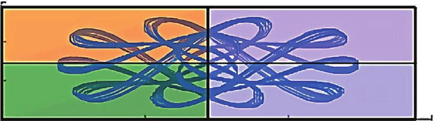
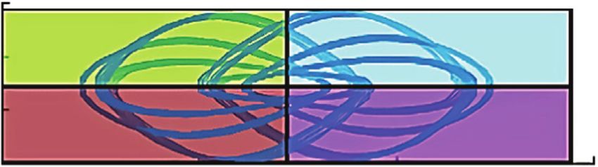
Mathematical Problems in Engineering 9

3.1.6. Hadley System. The initial conditions were taken as x The orbital distribution ratio (ODR) of the Lu–Chen
(0) � 0, y (0) � 0 ve, and z (0) � 1.3 in the differential equation chaotic system was calculated as in Table 5 with ODR
of the Hadley chaotic attractor [A] seen in the following calculation software developed in the MATLAB platform.
equation:
 x � −y2 − z2 − 0.25 · x + 2, 3.2.3. Circular Motion ODR. The time series obtained for the
 y � x · y − 4 · x · z − y + 1, (12) circular motion with the software developed in the MAT-
 LAB platform is shown in Figure 19, while the three-di-
 z � 4 · x · y + x · z − z.
 mensional phase portraits are shown in Figures 20–22.
 The orbital distribution ratio (ODR) for the orbital
 motion was calculated with the ODR calculation software
3.1.7. Halvorsen System. The initial conditions were taken as developed in the MATLAB platform as seen in Table 6.
x (0) � −5, y (0) � 0 ve, and z (0) � 0 in the differential
equation of the Halvorsen chaotic attractor [A] seen in the
following equation:
 4. Mixing Experiments
 x � −1.27 · x − 4 · y − 4 · z − y2 , A mixture of water and sugar was preferred as the solution
 to be used in mixing experiments. Due to the physical
 y � −1.27 · y − 4 · z − 4 · x − z2 , (13) structure of the chaotic mixer, 19.5 liters of water and 0.5
 z � −1.27 · z − 4 · x − 4 · y − x2 . liters of sugar, in total 20 liters of solutions were prepared in
 the cubic mixing vessel for each experiment. The mixing
 experiments were performed first for the Sprott_A chaotic
 system with the highest ODR and the Lu–Chen chaotic
3.2. Comparison of Chaotic Systems and Circular-Motion
 system with the lowest ODR. Then, the experiments were
Orbital Distribution Rates. For 7 different chaotic systems
 repeated for the circular and constant position motion of
and circular motion developed in the MATLAB platform,
 the propeller mixer. For 4 different experimental studies, a
the orbital distribution rates (ODR) obtained at the end of
 5-minute period was selected from the interface
the same numerical solution iterations entered through the
 programme.
software were calculated as in Table 3. According to Table 4,
the Sprott_A system has been the chaotic system which has
the highest ODR with 93.7%. The Lu–Chen system is the 4.1. Homogeneity Tests of Mixtures. The MA871 digital Brix
chaotic system which has the lowest ODR with 40.1%. The refractometer, seen in Figure 23, was used for the homo-
ODR values belonging to other chaotic systems were found geneity test of the sugar-water mixture. MA871 is an optical
between ODR values belonging to the Sprott_A and Lu– device using refractive index measurement to determine the
Chen systems, as shown in Table 3. The ODR obtained for amount of soluble dry matter (Brix) as a percentage in
the circular motion is shown as 42.9%. aqueous solutions. The method is both simple and fast.
 The calculation data of the Sprott_A system having the Samples are measured after a simple user calibration with
highest ODR were given in Section 3.2.1, the calculation data deionized or distilled water. The meter can measure the
of the Lu–Chen system having the lowest ODR were given in refractive index of the sample in a few seconds and convert it
Section 3.2.2, and the data of the ODR calculation for the to a Brix concentration unit [66].
circular motion was given in Section 3.2.3. Since the ODR Since 19,500 grams of water and 500 grams of sugar were
data of the other systems were not used in experimental used for the sugar-water mixture, the maximum sugar ratio
studies, they have not been presented in this article. that can be measured with the measuring device for this
 mixture has been 500/(19500 + 500) � 0.025. In other words,
3.2.1. ODR Data of the Sprott_A System. The time series for the maximum sugar ratio that can be measured is uttermost
the Sprott_A chaotic system obtained with the software 2.5%. Calibration of the MA871 digital Brix refractometer
developed in the MATLAB platform are shown in Figure 11, was also performed according to these ratios.
and the three-dimensional phase portraits are shown in
Figures 12–14.
 ODR calculation software was developed in the MAT- 4.2. Results of Mixing Experiments. The homogeneity ratio
LAB platform, and the orbital distribution rate belonging to obtained at the end of the mixing experiment done by using
the Sprott_A chaotic system was calculated as seen in the Delta robot-based chaotic mixer and the Sprott_A
Table 4. system with the highest ODR is shown in Table 7.
 The homogeneity ratio obtained at the end of the mixing
 experiment carried out by using the Delta robot-based
3.2.2. ODR Data of the Lu–Chen System. The time series chaotic mixer and the Lu–Chen system with the lowest ODR
obtained for the Lu–Chen chaotic system with the software is shown in Table 8.
developed in the MATLAB platform are shown in Figure 15, The homogeneity ratio obtained at the end of the mixing
and 3-dimensional phase portraits are shown in experiment done with the circular motion system and the
Figures 16–18. Delta robot based chaotic mixer is as shown in Table 9.
10 Mathematical Problems in Engineering

 Table 3: Comparison of chaotic systems and circular motion ODR.
 Time Zone- Zone- Zone- Zone- Zone- Zone- Zone- Zone- Total Orbital
Systems
 (Min.) 1% 2% 3% 4% 5% 6% 7% 8% % distribution rates
Orbital 5 0 0 0 0 24,90 24,90 25,10 25,10 100,0 42,9
Sprott A 5 13,1 14,1 13,9 14,4 10,9 10,7 11,4 11,5 100,0 93,7
Pehlivan–Wei 5 4,4 12,6 13,8 33,4 0,7 10,7 8,4 16,0 100,0 70,5
Aizawa 5 18,7 8,6 10,8 3,9 27,8 11,6 11,2 7,4 100,0 75,4
Guckenheimer–Holmes 5 3,9 7,3 6,3 25,1 4,2 7,6 8,5 37,1 100,0 57,5
Lu–Chen 5 0 0 0 0 46,3 16,1 9,8 27,5 100,0 40,1
Hadley 5 0,0 23,0 3,6 19,8 0,8 29,8 0,4 22,6 100,0 48,3
Halvorsen 5 0,4 20,6 21,2 11,0 21,1 11,6 12,5 1,6 100,0 71,0

 Table 4: ODR belonging to the Sprott-A chaotic system.
Zone-1% Zone-2% Zone-3% Zone-4% Zone-5% Zone-6% Zone-7% Zone-8% Total % Orbital distribution rates
13,1 14,1 13,9 14,4 10,9 10,7 11,4 11,5 100,0 93,7

 150 150
 Servo X Servo X
 100 Servo Y 100 Servo Y
 Degree

 Degree
 Servo Z Servo Z
 50 50

 0 0
 0 5 10 15 20 25 30 0 1 2 3 4 5 6 7 8 9 10
 Time Time
 Figure 11: x-y-z time series of the Sprott A system. Figure 15: x-y-z time series of the Lu–Chen system.

 150 150

 100 100
 Servo Z
 Servo Z

 50
 50
 0
 0 150
 150 100 150
 100 150 100
 100 Serv 50 50
 50 oY 0 0 Servo X
 Servo Y
 50 Servo X
 0 0
 Figure 16: 3D phase portrait of the Lu–Chen system.
 Figure 12: 3D phase portrait of the Sprott A system.

 150 150

 100 100
 Servo Y

 Servo Y

 50 50
 0 0
 0 50 100 150 0 50 100 150
 Servo X Servo X

 Figure 13: x-y phase portrait of the Sprott A system. Figure 17: x-y phase portrait of the Lu–Chen system.

 150 150

 100 100
 Servo Z

 Servo Z

 50 50

 0 0
 0 50 100 150 0 50 100 150
 Servo X Servo X

 Figure 14: x-z phase portrait of the Sprott A system. Figure 18: x-z phase portrait of the Lu–Chen system.
Mathematical Problems in Engineering 11

 Table 5: ODR belonging to the Lu–Chen chaotic system.
Zone-1% Zone-2% Zone-3% Zone-4% Zone-5% Zone-6% Zone-7% Zone-8% Total % Orbital distribution rates
0 0 0 0 46,3 16,1 9,8 27,5 100,0 40,1

 150
 Servo X
 100 Servo Y

 Degree
 Servo Z
 50

 0
 0 5 10 15 20 25 30
 Time
 Figure 19: x-y-z time series of the circular motion.

 150
 100
 Servo Z

 50
 0
 150
 100 150
 100
 Serv 50 50
 oY 0 0 Servo X

 Figure 20: 3D phase portrait of the circular motion system.

 150

 100
 Servo Y

 50

 0
 0 50 100 150
 Servo X

 Figure 21: x-y phase portrait of the circular motion system.

 150

 100
 Servo Z

 50

 0
 0 50 100 150
 Servo X

 Figure 22: x-z phase portrait of the circular motion system.

 Table 6: Circular motion ODR.
Zone-1% Zone-2% Zone-3% Zone-4% Zone-5% Zone-6% Zone-7% Zone-8% Total % Orbital distribution rates
0 0 0 0 24,90 24,90 25,10 25,10 100,0 42,9

 The homogeneity ratio obtained at the end of the mixing that the Sprott_A system had the highest homogeneity
experiment performed with the constant motion of the measurement ratio with 72%. The homogeneity ratio was
propeller mixer is shown in Table 10. measured 60% in the Lu–Chen system, 64% in the circular
 When the homogeneity ratios obtained at the end of 4 motion system, and 52% in the constant motion of the
different mixing tests are checked (Tables 7–10), it was seen propeller.
12 Mathematical Problems in Engineering

 Figure 23: MA871 digital Brix refractometer.

 Table 7: The homogeneity rate obtained in the mixing experiment done with the Sprott_A chaotic system.
 Orbital
 Total Measured Homogeneity
Zone-1% Zone-2% Zone-3% Zone-4% Zone-5% Zone-6% Zone-7% Zone-8% distribution
 % sugar rate rate
 rates
13,1 14,1 13,9 14,4 10,9 10,7 11,4 11,5 100,0 93,7 1,8 72,0

 Table 8: The homogeneity rate obtained in the mixing experiment done with the Lu–Chen chaotic system.
 Orbital
 Total Measured Homogeneity
Zone-1% Zone-2% Zone-3% Zone-4% Zone-5% Zone-6% Zone-7% Zone-8% distribution
 % sugar rate rate
 rates
0 0 0 0 46,3 16,1 9,8 27,5 100,0 40,1 1,5 60,0

 Table 9: The homogeneity rate obtained in the mixing experiment done with the circular motion system.
 Orbital
 Total Measured Homogeneity
Zone-1% Zone-2% Zone-3% Zone-4% Zone-5% Zone-6% Zone-7% Zone-8% distribution
 % sugar rate rate
 rates
0 0 0 0 24,90 24,90 25,10 25,10 100,0 42,9 1,6 64,0

 Table 10: The homogeneity rate obtained in the mixing experiment performed with the constant motion of the propeller mixer.
 Orbital
 Total Measured Homogeneity
Zone-1% Zone-2% Zone-3% Zone-4% Zone-5% Zone-6% Zone-7% Zone-8% distribution
 % sugar rate rate
 rates
0 0 0 0 0 0 0 0 0 0 1,3 52,0

5. Conclusions simulation ODRs. According to the results, the Sprott_A
 system was the chaotic system with the highest ODR of
This study had been carried out by designing a new delta 93.7%, while the Lu–Chen system was the chaotic system
robot-based chaotic mixer. With the algorithm developed in with the lowest ODR of 40.1%. The circular motion ODR was
MATLAB, the amplitude values of time series produced found out as 42.9%.
from chaotic systems were converted to 3-dimensional Mixing experiments were carried out for the Sprott_A
position information for servo motors used in the mixer. The system with the highest ODR, Lu–Chen system with the
chaotic position information was transferred to the Arduino lowest ODR, and mixing propeller’s constant and circular
Uno R3 card allowing the newly designed chaotic mixer to motion movement. 5-minute periods were selected for all 4
be checked to pace chaotically on the x, y, and z coordinates. different experimental studies. Due to the physical structure
 With the software developed in MATLAB, the perfor- of the chaotic mixer, 20 liters of solutions, consisting of
mances of trajectories which belong to 7 different chaotic 19.5 liters of water and 0.5 liters of sugar were prepared for
systems and the performances of circular motion trajectories each experiment. The MA871 digital Brix refractometer
were evaluated by comparing them over the numerical measurement device was used to measure the homogeneity
Mathematical Problems in Engineering 13

rate of the solution in the mixing tests. As a result of the sequences in CAD/CAM,” Procedia Engineering, vol. 192,
experiments, the Sprott_A system was the system with the pp. 113–118, 2017.
highest homogeneity measurement ratio with 72%. The [8] P. Bozek and Y. Turygin, “Measurement of the operating
Lu–Chen system was 60%, the circular motion system was parameters and numerical analysis of the mechanical sub-
64%, and the constant motion of the propeller was 52%. The system,” Measurement Science Review, vol. 14, no. 4, 2014.
system with the highest homogeneity measurement ratio [9] P. Bozek, A. A. Akkad, P. Blistan, and I. Ibrahim, “Navigation
 control and stability investigation of a mobile robot based on a
was the Sprott_A system as in the ODR calculations. It has
 hexacopter equipped with an integrated manipulator,” In-
been observed that even the Lu–Chen chaotic system with
 ternational Journal of Advanced Robotic Systems, vol. 14, no. 6,
the lowest ODR yields better results than the constant pp. 1–13, 2017.
moving mixing process. [10] A. Kilin, P. Bozek, Y. Karavaev, A. Klekovkin, and
 When evaluated in terms of mixing time, it was found V. Shestakov, “Experimental investigations of a highly ma-
that the Sprott A system achieved the same uniformity ratio neuverable mobile omniwheel robot,” International Journal of
in 20% less time than the circular motion mixing process and Advanced Robotic Systems, vol. 14, no. 6, pp. 1–9, 2017.
40% less than the fixed motion process. [11] J. Angeles, Fundamentals of Robotic Mechanical Systems:
 It is thought that this prototype presented in the article Theory, Methods and Algorithms, Springer, Berlin, Germany,
can serve the purpose of developing new chaotic mixer 1997.
systems and algorithms that can produce homogeneous [12] P. J. Zsombo-Murray, Descriptive Geometric Kinematic
mixtures of the same quality with less working time and less Analysis of Clavel’s “Delta” Robot, McGill University, De-
power consumption instead of the fixed and circular moving partment of Mechanical Engineering, Centre for Intelligent
mixers widely used today. Machines, Montreal, Canada, 2004.
 [13] I. H. Sanliturk, Investigation of Delta Robot Design and
 In the next study, using artificial intelligence techniques,
 Performance Characteristics, Fırat University, Institute of
it is aimed that the chaotic mixer automatically decides
 Natural Sciences, Department of Mechanical Engineering,
which chaotic system it will work with according to the state Elazığ, Turkey, 2012.
of the mixture. [14] Y. Qiaoling, J. Shiming, W. Zhongfei, W. Guan, W. Yuehua,
 The results obtained in this study will be helpful with and Z. Li, “Optimal design of the linear delta robot for
other studies in the fields such as materials science and prescribed cuboid dexterous workspace based on perfor-
nanotechnology engineering [33, 67], 3D printing tech- mance chart,” in Proceedings of the 8th WSEAS International
nology [68], biological fluid dynamics [69], medical/bio- Conference on Robotıcs, Control And Manufacturıng Tech-
medical sciences, and food and chemical industries [70]. nology (Rocom’08), pp. 35–41, Hangzhou, China, April 2008.
 [15] L. Xin-Jun, W. Jinsong, O. Kun-Ku, and K. Jongwon, “A new
Data Availability approach to the design of a delta robot with the desired
 workspace,” Journal of Intelligent and Robotic Systems, vol. 39,
No data were used to support this study. pp. 209–225, 2004.
 [16] U. Cavusoglu, Y. Uyaroğlu, and İ. Pehlivan, “Design of a
 continuous-time autonomous chaotic circuit and application
Conflicts of Interest of signal masking,” Journal of the Faculty of Engineering and
The authors declare that they have no conflicts of interest. Architecture of Gazi University, vol. 29, no. 1, pp. 79–87, 2014.
 [17] I. Koyuncu, A. Ozcerit, and I. Pehlivan, “An analog Ccircuit
 design and FPGA-based implementation of the burke-shaw
References chaotic system,” Optoelectronics and Advanced Materi-
 als–Rapid Communications, vol. 7, no. 9-10, pp. 635–638,
 [1] E. Kurt, A New Chaotic Mixer Design and Application, Sakarya
 2013.
 University, Institute of Natural Sciences, Sakarya, Turkey,
 [18] L. Chunbiao, I. Pehlivan, and J. C. Sprott, “Amplitude-phase
 2017.
 control of a novel chaotic attractor,” Turkish Journal of
 [2] J. T. Banhero and W. L. Bodger, Introduction to Chemical
 Engineering, pp. 731–737, ITU Publications, Geneva, Swit- Electrical Engineering & Computer Sciences, vol. 24, no. 1,
 zerland, 1979. pp. 1–11, 2016.
 [3] W. Vauck and H. Müler, Basic Operations of Chemical En- [19] I. Pehlivan, Y. Uyaroglu, and M. Yogun, “Chaotic oscillator
 gineering Introduction, pp. 307–328, Theodor Steinkopff, design and realizations of the rucklidge attractor and its
 Magdeburg, Germany, 1966. synchronization and masking simulations,” Scientific Re-
 [4] J. Henzler and H. Eignung, Von Kontinuierlich Durchströmten search and Essays, vol. 5, no. 16, pp. 2210–2219, 2010.
 Mischern Zum Homogenisieren, pp. 1–8, WILEY-VCH pub- [20] M. Alcin, I. Pehlivan, and I. Koyuncu, “Hardware design and
 lications, Hoboken, NJ, USA, 1972. implementation of a novel ANN-based chaotic generator in
 [5] N. Ilten, Investigation of Current Events in Mixers and Mixing FPGA,” OPTIK-international Journal for Light and Electron
 Vessel, Uludağ University, Institute of Natural Sciences, Optics, vol. 127, no. 13, pp. 5500–5505, July 2016.
 Department of Mechanical Engineering, Bursa, Turkey, 1986. [21] M. Alcin, I. Koyuncu, M. Tuna, M. Varan, and I. Pehlivan, “A
 [6] B. A. Can, Mixing of Different Fluids in the Mixing Vessel and novel high speed artificial neural network–based chaotic true
 Analysis of the Temperature Distribution, Erciyes University, random number generator on field programmable gate array,”
 Institute of Natural Sciences, Department of Mechanical International Journal of Circuit Theory and Applications,
 Engineering, Kayseri, Turkey, 2010. vol. 47, no. 3, 2018.
 [7] T. Dodok, N. Čuboňová, M. Cı́sar, I. Kuric, and I. Zajačko, [22] U. Cavusoglu, S. Kacar, A. Zengin, and I. Pehlivan, “A novel
 “Utilization of strategies to generate and optimize machining hybrid encryption algorithm based on chaos and S-AES
14 Mathematical Problems in Engineering

 algorithm,” Nonlinear Dynamics, vol. 92, no. 4, pp. 1745–1759, [39] S. Ozoguz and A. Zeki, “Integrated implementation of con-
 2018. tinuous time chaotic systems and their use in random number
[23] U. Cavusoglu, A. Akgul, A. Zengin, and I. Pehlivan, “The generation,” Tubitak Project Final Report, (106E093), 2008.
 design and implementation of hybrid RSA algorithm using a [40] K. Ozdemir, Random Number Generator Design with Con-
 novel chaos based RNG,” Chaos, Solitons & Fractals, vol. 104, tinuous Time Chaos, Istanbul Technical University, Istanbul,
 pp. 655–667, 2017. Turkey, 2008.
[24] U. Cavusoglu, A. Zengin, I. Pehlivan, and S. Kacar, “A novel [41] S. Coskun, Design and Implementation of Chaos Sourced and
 approach for strong S-Box generation algorithm design based Adc Based Novel True Random Number Generators, Sakarya
 on chaotic scaled zhongtang system,” Nonlinear Dynamics, University, Institute of Natural Sciences, Department of
 vol. 87, no. 2, pp. 1081–1094, 2017. Electrical and Electronics Education, Sakarya, Turkey, 2017.
[25] A. Ozdemir, I. Pehlivan, A. Akgül, and E. Güleryüz, “A [42] N. K. Pareek, V. Patidar, and K. K. Sud, “Image encryption
 strange novel chaotic system with fully golden proportion using chaotic logistic map,” Image and Vision Computing,
 equilibria and its mobile microcomputer-based RNG appli- vol. 24, no. 9, pp. 926–934, 2006.
 cation,” Chinese Journal of Physics, vol. 56, no. 6, [43] F. E. Udwadia and R. S. Guttalu, “Chaotic Dynamics of a
 pp. 2852–2864, 2018. piecewise cubic map,” Physical Review A, vol. 40, no. 7,
[26] A. Akgul, C. Arslan, and B. Aricilioglu, “Design of an interface pp. 4032–4044, 1989.
 for random number generators based on integer and frac- [44] B. Saha, S. Tej Malasani, and J. B. Seventline, “Application of
 tional order chaotic systems,” Chaos Theory and Applications, modified chaotic sine map in secure communication,” In-
 vol. 1, no. 1, pp. 1–18, 2019. ternational Journal of Computer Applications, vol. 113, no. 13,
[27] I. Pehlivan, K. Ersin, L. Qiang, A. Basaran, and M. Kutlu, “A pp. 9–13, 2015.
 multi scroll chaotic attractor and its electronic circuit [45] A. Vladi, A. Luca, O. Hodea, and R. Tataaru, Generating
 implementation,” Chaos Theory and Applications, vol. 1, no. 1, Chatic Secure Sequence Using Tent Map and Running-Key
 pp. 29–37, 2019. Approach, pp. 295–302, The Publishing House of The Ro-
[28] K. T. Chau, Y. Shuang, G. Yuan, and J. H. Chen, “Application manian Academy, Bucharest, Romania, 2013.
 of chaotic-motion motors to industrial mixing processes,” [46] B. F. Vajargah and R. Asghari, “A pseudo random number
 generator based on chaotic henon map (CHCG),” Interna-
 IAS2004, pp. 1874–1880, Wiley, Hoboken, NJ, USA, 2004.
[29] S. Ye and K. T. Chau, “Destabilization control of a chaotic tional Journal of Mechatronics, Electrical and Computer
 Technology (IJMEC), vol. 5, no. 15, pp. 2120–2129, 2015.
 motor for industrial mixers,” IAS2005, pp. 1724–1730, Wiley,
 [47] M. A. Aziz-Alaoui, C. Robert, and C. Grebogi, “Dynamics of a
 Hoboken, NJ, USA, 2005.
 Hénon-Lozi-type map,” Chaos, Solitons & Fractals, vol. 12,
[30] S. Ye and K. T. Chau, “Chaoization of DC motors for in-
 no. 12, pp. 2323–2341, 2001.
 dustrial mixing,” IEEE Transactions on Industrial Electronics,
 [48] R. Senkerik, I. Zelinka, M. Pluhacek, and Z. K. Oplatkova,
 vol. 54, no. 4, 2007.
 “Evolutionary control of chaotic burgers map by means of
[31] M. A. Murtadha, M. Abdurrahman, and A. I. Korman,
 chaos enhanced differential evolution,” International Journal
 Chaotic Control of Liquid Mixer, The University of Sharjah,
 of Mathematics and Computers in Simulation, vol. 8,
 Department Of Electrical & Computer Engineering. Senior
 pp. 39–45, 2014.
 Design Project II, Sharjah, UAE, 2008. [49] S. M. Sohel Rana, “Chaotic dynamics in a discrete-time
[32] Z. Zhang and G. Chen, “Liquid mixing enhancement by
 predator-prey food chain,” Computational Ecology and
 chaotic perturbations in stirred tanks,” Chaos, Solitons & Software, vol. 5, no. 1, pp. 28–47, 2015.
 Fractals, vol. 36, no. 1, pp. 144–149, 2008. [50] M. Mishra, A. Ranjan Routray, and S. Kumar, “High security
[33] A. E. Kavur, S. Demiroğlu, M. Ö. Seydibeyoğlu, Ö. Baser, image steganography with modified Arnold’s Cat map,” In-
 C. Güzelis, and S. Şahin, “Design and implementation of ternational Journal of Computer Applications, vol. 37, no. 9,
 chaotic system based robust delta robot for blending graphene pp. 16–20, 2012.
 nanoplatelets,” in Proceedings of the 2016 21st International [51] J. C. Butcher, Numerical Methods for Ordinary Differential
 Conference on Methods and Models in Automation and Ro- Equations, John Wiley & Sons, Hoboken, NJ, USA, 2008.
 botics (MMAR), IEEE, Miedzyzdroje, Poland, August 2016. [52] W. Zhang, Z. Gui, and K. Wang, “Impulsive control for
[34] I. Pehlivan, New Chaotic Systems: Electronic Circuit Reali- synchronization of lorenz chaotic system,” Journal of Software
 zations, Synchronization and Secure Communication Appli- Engineering and Applications, vol. 5, no. 12, pp. 23–25, 2013.
 cations, Sakarya University, Institute of Natural Sciences, [53] R.-E. Precup, M.-L. Tomescu, and C.-A. Dragos, “Stabilization
 Department of Electrical and Electronics Engineering, of Rössler chaotic dynamical system using fuzzy logic control
 Sakarya, Turkey, 2007. algorithm,” International Journal of General Systems, vol. 43,
[35] P. S. Addison, Fractals and Chaos, an Illustrated Course, no. 5, pp. 413–433, 2014.
 pp. 5–7, IOP Publishing Limited, Bristol, UK, 1997. [54] L.-J. Sheu, H.-K. Chen, J.-H. Chen, and L.-M. Tam, “Chaotic
[36] R. C. Hilborn, “An introduction for scientists and engineers,” dynamics of the fractionally damped Duffing equation,”
 Chaos and Nonlinear Dynamics, Oxford University Press, Chaos, Solitons & Fractals, vol. 32, no. 4, pp. 1459–1468, 2007.
 Oxford, UK, 1994. [55] M. Kuetche, E. S. Fotsin, H. B. Kengne, and P. Woafo,
[37] I. Koyuncu, Design and Implementation of FPGA-Based New ““Parameters estimation based adaptive GPS of chaotic
 Chaotic Oscillators and Real Random Number Generators for Chua’s circuit with application to chaos communication by
 Cryptological Applications, Sakarya University, Institute of parametric modulation,” Chaos, Solitons & Fract, pp. 27–37,
 Natural Sciences, Sakarya, Turkey, 2014. Elsevier, Amsterdam, Netherlands, 2014.
[38] A. Akgul, Random Number Generator Design with New [56] V. Sundarapandian, “Global chaos synchronization of the
 Chaotic Systems and High Security Encryption of Multimedia forced van der pol chaotic oscillators via adaptive control
 Data, Sakarya University, Institute of Natural Sciences, method,” International Journal of PharmTech Research, vol. 8,
 Sakarya, Turkey, 2015. no. 6, pp. 156–166, 2015.
Mathematical Problems in Engineering 15

[57] G. Chen and T. Ueta, Chaos in Circuits and Systems, World
 Scientific Pub. Co., Singapore, 2002.
[58] V. Vembarasan and P. Balasubramaniam, “Chaotic syn-
 chronization of Rikitake system based on T-S fuzzy control
 techniques,” Nonlinear Dynamics, vol. 74, no. 1-2, pp. 31–44,
 2013.
[59] A. M. Rucklidge, “Chaos in models of double convection,”
 Journal of Fluid Mechanics, vol. 237, pp. 209–229, 1992.
[60] V. Sundarapandian, “Global chaos synchronization of ruck-
 lidge chaotic systems for double convection via sliding mode
 control,” International Journal of ChemTech Research, vol. 8,
 no. 8, pp. 61–72, 2015.
[61] V. Sundarapandian, “Output regulation of the arneodo
 chaotic system,” International Journal on Computer Science
 and Engineering (IJCSE), vol. 2, no. 5, pp. 1601–1608, 2010.
[62] Z.-L. Wang and X.-R. Shi, “Chaotic bursting lag synchroni-
 zation of hindmarsh-rose system via a single controller,”
 Applied Mathematics and Computation, vol. 215, no. 3,
 pp. 1091–1097, 2009.
[63] W. Zhongtang, M. Wang, J. Jianxiu, and F. Jiuchap, “A Novel
 strange attractor and its dynamic analysis,” Journal of Mul-
 timedia, vol. 9, no. 3, pp. 408–415, 2014.
[64] R. Neugebauer, V. Wittstock, and W. Drossel, Werkzeug-
 maschinen Mechatronic, Chemnitz University of Technology,
 Chemnitz, Germany, 2010.
[65] E. Ozkilic, Parametrical Simulation of 3 Freedom Delta Robot
 Mechanisms with Matlab-Simmechanics, Yildiz Technical
 University, Institute of Natural Sciences, Department of
 Mechanical Engineering, Istanbul, Turkey, 2012.
[66] http://www.milwaukeeinst.com/site/products/products/
 digital-refractometers/165-products-g-digital-
 refractometers-g-ma871.
[67] S. Şahin, A. E. Kavur, S. D. Mustafov et al., “Spatiotemporal
 chaotification of delta robot mixer for homogeneous graphene
 nanocomposite dispersing,” Robotics and Autonomous Sys-
 tems, vol. 134, 2020.
[68] D. Therriault, S. R. White, and J. A. Lewis, “Chaotic mixing in
 three-dimensional microvascular networks fabricated by di-
 rect-write assembly,” Nature Materials, vol. 2, no. 4,
 pp. 265–271, 2003.
[69] M. A. Jalali, A. Khoshnood, and M.-R. Alam, “Micro-
 swimmer-induced chaotic mixing,” Journal of Fluid Me-
 chanics, vol. 779, pp. 669–683, 2015.
[70] S. K. Lao, H. K. Chen, L. M. Tam, and L. J. Sheu, “Microfluidic
 mixing using chaotic signals from the Chen-Lee system,” in
 Proceedings of the International Conference on Advanced
 Robotics and Intelligent Systems (ARIS), Taipei, Taiwan, May
 2015.
You can also read