AN AUTOMATED SIZE RECOGNITION TECHNIQUE FOR ACETABULAR IMPLANT IN TOTAL HIP REPLACEMENT
←
→
Page content transcription
If your browser does not render page correctly, please read the page content below
International Journal of Computer Science & Information Technology (IJCSIT), Vol 3, No 2, April 2011

AN AUTOMATED SIZE RECOGNITION TECHNIQUE
   FOR ACETABULAR IMPLANT IN TOTAL HIP
              REPLACEMENT
                   A. Shapi’i1, R. Sulaiman2, M.K. Hasan3 and A.Y.M. Kassim4
       1
        Industrial Computing Research Group, Universiti Kebangsaan Malaysia, Malaysia
                                    azrul@ftsm.ukm.my
         2
           School of Information Technology, Universiti Kebangsaan Malaysia, Malaysia
                                      rs@ftsm.ukm.my
           3
             Information Technology Center, Universiti Kebangsaan Malaysia, Malaysia
                                   khatim@ftsm.ukm.my
    4
      Department of Orthopaedic and Traumalogy, Medical Center of Universiti Kebangsaan
                                            Malaysia
                                   dryazidk@gmail.com

ABSTRACT
Preoperative templating in Total Hip Replacement (THR) is a method to estimate the optimal size and
position of the implant. Today, observational (manual) size recognition techniques are still used to find a
suitable implant for the patient. Therefore, a digital and automated technique should be developed so that
the implant size recognition process can be effectively implemented. For this purpose, we have introduced
the new technique for acetabular implant size recognition in THR preoperative planning based on the
diameter of acetabulum size. This technique enables the surgeon to recognise a digital acetabular implant
size automatically. Ten randomly selected X-rays of unidentified patients were used to test the accuracy
and utility of an automated implant size recognition technique. Based on the testing result, the new
technique yielded very close results to those obtained by the observational method in nine studies (90%).

KEYWORDS
Total hip replacement, implant, templating, digital, preoperative, x-ray

1. INTRODUCTION
The field of orthopaedics at the time became more important as the number of patients suffering
from osteoporosis increased every year [1]. According to experts from PPUKM, the
conventional detection method was used to search for a suitable implant for the patient. The
method involves using the implant templates supplied by the supplier, and then the image of the
implant is measured by doing image mapping on a patient’s scanned X-ray. This step was used
repeatedly until the appropriate implant of the patient encountered. However, the survey found
that this procedure requires a long time, and is said to be less efficient [2].
   Demand for orthopaedic medicine has increased over the past 20 years, based on the
increasing number of patients each year [3]. Before surgery is performed, a conventional
orthopaedic image identification is done by manually matching the articial implant image with a
patient X-ray by an orthopaedic specialist. This method is a conventional method to determine
the patient’s implant size. But the manual or observational procedures require a long time to
recognize the size of the patient’s implant because the method used is repeated several times.
Thus, the manual procedure should be changed to a digital and automated technique, or more
accurately by using software. This technique helps the surgeon identify the appropriate patient’s
implant size digitally and automatically. Several studies have shown that a digital technique can
improve the placement of a total hip implant [4-7].

DOI : 10.5121/ijcsit.2011.3218                                                                        236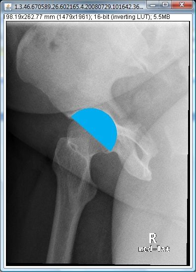
International Journal of Computer Science & Information Technology (IJCSIT), Vol 3, No 2, April 2011

2. SCOPE AND OBJECTIVES
The main objective of this research is to produce a technique which can automatically recognize
the size of patient’s acetabular implant in total hip replacement surgery. Particularly, in order to
achieve these goals, the main objectives of the research that has been identified are:

            i.  Studying and designing techniques for the recognition of hip replacement
                acetabular implant size.
            ii. Implementing the techniques developed.

3. RESEARCH BACKGROUND
An acetabular implant size recognition technique to be developed involves a number of things
that need to be studied carefully. The technique could be developed to recognize the size of the
acetabular implant accurately and effectively. In this section, the techniques and other related
matters will be discussed.

3.1 Computer Aided Design
Computer Aided Design, better known as CAD, is defined as a system that uses computers to
assist in designing and sketching work [8]. CAD is very helpful in some areas such as the use
of appropriate scale, object manipulation, display and printing. Currently, there are various
types of CAD software such as AutoCAD, Solidworks, CATIA, and MasterCAM. In this study,
CAD will be used to design the related implant. Examples of implant that were designed using
AutoCAD software can be seen in Figure 1.

                               Figure 1. Acetabular implant design

                                                                                                 237
International Journal of Computer Science & Information Technology (IJCSIT), Vol 3, No 2, April 2011
3.2 Digital X-Ray Images
 X-ray is a type of radiation used in medical images for diagnosing diseases like cancer and
fractures [9]. The radiologist takes X-ray images by putting on an X-ray to an opposite source
of the part that needs to be imaged or convert it into films. Then, the image can be generated
into films or stored digitally. The difference between a digital X-ray and a general X-ray is that
the output given in the first case is in a digital form while the general X-ray is in films. A digital
X-ray may be edited and stored in a computer database. While a general x-ray only provides a
negative film output as a reference. An example of a digital X-ray can be seen in Figure 2. An
x-ray image is stored in JPEG format using software MedWeb [10].

                                       Figure 2. Digital X-ray

Each digital x-ray image has a different resolution depending on the amount of image
compression. The purpose compression is done is to reduce the file size so that the use of
memory space can be reduced, and to accelerate the transfer of files. The disadvantage of
compression is that it can affect the image quality. Therefore, an appropriate resolution and
techniques in scaling digital X-Ray images should be produced because the size of the implant
identification technique to be developed depends on the accuracy of the image size of the
patient’s bone.
3.3 Image and Object Recognition Techniques
The image recognition operation is useful in helping to edit operation and object manipulation
interactively [11]. The object is polygon-based, and the points in the polygon can form a
polygon area. The polygon area can be identified by testing the position of the mouse on the
                                                                                                  238
International Journal of Computer Science & Information Technology (IJCSIT), Vol 3, No 2, April 2011
digital X-ray images area. Object recognition operations can be done by using the dots on the X-
ray images. This technique is very important because it can determine the optimum acetabular
implant size.
3.4 Total Hip Replacement (THR)
Every joint disease, whether inflammatory or trauma, - if the disease process is allowed to
continue - will cause erosion of cartilage and joint damage. When this happens, a patient may
complain of pain, swelling, deformity and instability of joints involved. There are several
methods of treatment for damaged joints. The first step is a move in the conservative treatment.
If this fails, then the next method of treatment is surgery. The most effective surgical method is
the total hip replacement THR surgery. This surgery involves an artificial joint that replaces the
original which is damaged. THR is a surgical procedure in which the hip joint is replaced by an
implant. THR surgery can be performed as a total replacement or a hemi (half) replacement
[12]. THR consists of replacing both the femoral head and the acetabulum.

3.4.1 Acetabulum
The acetabulum (see figure 3) is a concave surface of the pelvis. The head of the femur meets
with the pelvis at the acetabulum, forming the hip joint [12].

                                    Figure 3. The acetabulum

3.4.2 Acetabular

The acetabular implant is the component which is placed into the acetabulum (hip socket). Bone
and cartilage are removed from the acetabulum, and the acetabular implant is attached using
cement or friction. Some acetabular cups are one piece, others are modular. One piece shells are
either polyethylene or metal, they have their articular surface machined on the inside surface of
the cup and do not rely on a locking mechanism to hold a liner inplace [12]. Figure 4 shows the
acetabular implant used in THR, while figure 5 shows the acetabular position after THR is
performed [13].
                                                                                                 239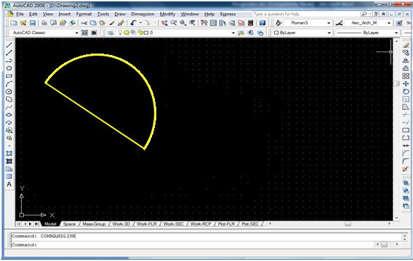
International Journal of Computer Science & Information Technology (IJCSIT), Vol 3, No 2, April 2011

                                  Figure 4. Acetabular implant

                     Figure 5. Acetabular position after THR is performed

3.4.3 Acetabular Conventional Templating

Prior to surgery, the template preparation process is very important because it is a screening
process in which an orthopaedic specialist can determine the optimal implant size before
surgery. The orthopaedic specialist will do the adjustment process of the implant templates first
before bringing the results into the operating room. In the operating room, the orthopaedic
specialist will make the final selection of the appropriate implant size. The use of implants in
the template customization process on the X-ray image of a patient before surgery can provide
important information to the orthopaedic specialist in determining the size of the implant to be
used [14]. By using the observational or manual method, any error in template transformation
such as rotating and scaling while recording the patient's hip bone radiographs prior to the
surgery will lead to errors in determining the size of implant. Thus, the templating process

                                                                                                 240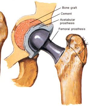
International Journal of Computer Science & Information Technology (IJCSIT), Vol 3, No 2, April 2011
should be done cautiously. Fig. 6 shows the process of manual implant templating for acetabular
component [15].

                         Figure 6. Manual acetabular implant templating

4. MATERIALS AND METHOD
The main activity to implement is to analyze the existing techniques for the implant recognition
process. The technique analysis aims to identify similar techniques or that have been
implemented or are being implemented by other researchers around the world. The process of
producing a new technique for the implant size recognition is to take into account the improved
methodology to be adopted on the latest techniques. the new method that has the potential to be
developed is the automated recognition of the digital acetabular implant size. This means that
the surgeons do not have to use a trial and error method to select the appropriate implant size
[16].
   The second objective of the research is to implement the new techniques produced by
developing a system that consists of modules of the new technique. This aims to ensure that new
techniques will be developed to be implemented effectively. In addition, the system will be
developed to include other modules such as the transformation of the image, measuring the size
and angle, and so forth. An appropriate programming language is to be used for this purpose.
After a new technique has been implemented, the next phase is to do testing and comparison.
The aim is to ensure that this new technique can effectively recognize the implant size, and to
assist physicians in carrying out the pre-operative process before the surgery in order for it to be
more efficient and organized.

4.1 Acetabular Implant Template
Fig. 7 shows the acetabular implant template used by PPUKM surgeons in the THR
preoperative planning procedure.

                                                                                                 241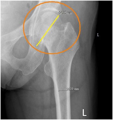
International Journal of Computer Science & Information Technology (IJCSIT), Vol 3, No 2, April 2011

                                      Figure 7. Acetabular template

4.2 Digital Implant
Digital implants produced using Autocad 2008 and Photoshop software can be seen in figure
8(a) and figure 8(b).

                        Figure 8(a). Digital acetabular implant (left hip)

                        Figure 8(b). Digital acetabular implant (right hip)

4.3 Acetabular Implant Detection Technique
The process of designing and producing new techniques of implant detection is taking into
consideration the method of improvement which will be implemented on the latest techniques.
                                                                                                 242
International Journal of Computer Science & Information Technology (IJCSIT), Vol 3, No 2, April 2011
Through literature studies, most of the implant detection techniques used a trial and error
method [2,3,5,6]. This means that surgeons need to try several sizes to get the optimum implant.
One of the potential new methods to be produced is the automated detection method.
   Detection techniques that will be generated are based on observational and computerized
techniques in which the implant template will be matched to the X-ray images. A Trial and
error method will be repeated several times until the appropriate size is found. The proposed
new technique has the ability to detect the size of the acetabular implant automatically. By using
the concept of distance between two points, acetabular implants will be selected based on the
patient’s acetabulum diameter size. Fig. 9 shows the proposed algorithm for the acetabular
implant size recognition technique.

     1.0: Draw a line on acetabulum diameter.

     2.0: Calculate the distance of the line.

     3.0: Size of the implant is chosen based on:
          3.2 If the distance has a decimal value, take the previous value.
          3.3 If the distance has an odd value, take the previous even value.

     4.0: Display acetabular implant

                     Figure 9. Acetabular implant size recognition algorithm
   In the algorithm shown in figure 9, the user must draw a line on the acetabulum diameter.
Line distance will be calculated, and the size of the implant will be determined by the
acetabulum diameter size. Sizing method involves three conditions, namely, if the size of the
implant is smaller than 36 mm or larger than 80 mm , then the implant will not be displayed.
This is because the TRILOGY acetabular system implant comes only in size from 36 mm to 80
mm. In addition, if the distance has a decimal value, the previous value will be taken. For
example, in figure 10, the distance of the line drawn on the acetabulum diameter is 64.15 mm,
therefore the value will be taken as 64 mm.

                              Figure 10. Line drawn on acetabulum
                                                                                                 243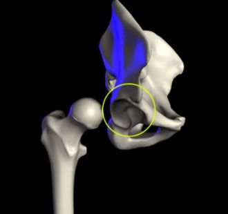
International Journal of Computer Science & Information Technology (IJCSIT), Vol 3, No 2, April 2011
5. RESULTS AND DISCUSSION
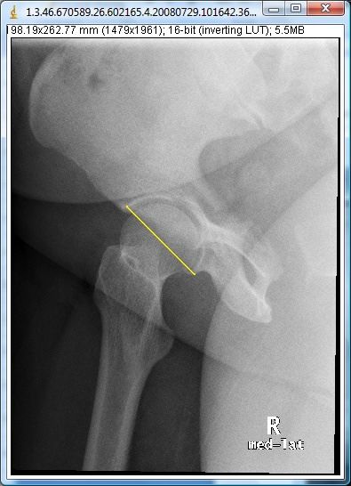
Based on the algorithm in Fig. 9, the first thing the user needs to do is draw a straight line on the
patient’s acetabulum diameter. Fig. 11 shows how to draw the line.
Figure 11. Straight line drawn on the acetabulum diameter
The distance between two points on the line will be calculated to determine the size of the
acetabular implant. In Fig. 11, the distance drawn on the acetabulum diameter was 58.28 mm, so
the value to be taken is 58 mm. An acetabular implant with 58 mm size will be displayed
automatically on the X-ray image (see fig. 12).
Figure 12. Acetabular implant default position
244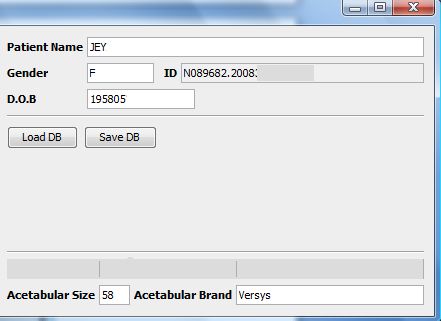
International Journal of Computer Science & Information Technology (IJCSIT), Vol 3, No 2, April 2011
   The size of the acetabular supplied by the PPUKM is an even number, so if there is an odd
number, the even value before the odd value will be taken as the size of the acetabular implant.
For example, if the distance drawn was 59.25 mm, the value to be taken is 58 mm. Table 1
shows the examples how to determine the acetabular size based on the distance between two
points.

                 Table 1. Acetabular size based on distance between two points

                                          Distance          Acetabular size
                          No.
                                           (mm)                 (mm)
                           1               48.58                  48
                           2               57.45                  56
                           3               58.15                  58
                           4               53.36                  52
                           5               66.45                  66
                           6               69.13                  68
                           7               72.78                  72
                           8               77.67                  76

   In Fig. 12, it can be seen that the position of the acetabular implant is still not in the optimum
position. The implant should be translated and rotated to get the optimum position. Figure 13(a)
shows the implant which is translated and rotated using the geometric transformation algorithm
[17], while figure 13(b) shows the information of implant and patient.

                      Figure 13(a). Implant that has been translated and rotated

                                                                                                 245
International Journal of Computer Science & Information Technology (IJCSIT), Vol 3, No 2, April 2011
Figure 13(b). Acetabular and patient’s information
To test the accuracy and utility of the acetabular implant size recognition technique, an
experiment was conducted with assistance from a surgeon for the observational (manual)
method to determine the acetabular implant size. The results by the observational approach were
compared to the results produced by our automated technique. The testing recorded the
acetabular implant size to be used and the time taken by both methods. Ten randomly selected
X-rays of unidentified patients were used for templating for both techniques. The difference
between the two sizes were calculated and shown in table 2.
Table 2. Observational vs Digital
Patient Stem Size Stem Size Size
(Observational) (Digital) Difference
1 48 48 0
2 54 52 ±2
3 50 50 0
4 52 52 0
5 46 46 0
6 48 46 ±2
7 52 52 0
8 58 54 ±4
9 56 54 ±2
10 54 54 0
It is evident that the new technique yields very close results to those obtained by the
observational method in nine studies (90%). The difference, if any, is also within the error of
clinically acceptable range (± 2 size determined by the surgeon) obtained by the observational
246International Journal of Computer Science & Information Technology (IJCSIT), Vol 3, No 2, April 2011
templating method (only one study (10%) is outside of clinically acceptable range). In addition,
the study also demonstrated that the average time taken for acetabular implant templating in
total hip replacement preoperative planning using an automated technique was much less than
using the observational method.
6. CONCLUSIONS
Preoperative templating has been useful to determine the optimum implant size in total hip
replacement (THR). With classical tracing paper now obsolete, we have developed a new
technique to undertake the templating procedure with a digital acetabular implant and an X-ray.
The digital implant provides several advantages for THR surgery. Compared to the
observational method in which the surgeon uses a template manually and places it on the
patient’s X-ray, the use of the digital implant not only saves time, but also can reduce the error
due to consistency difference when making adjustments to a patient’s implant size [14].
This new technique offers a simple solution to the problem of using the observational
method in THR. The technique allows users to choose the acetabular implant automatically on
computer prior to surgery, based on the diameter of the patient’s acetabulum size. The new
proposed acetabular implant detection technique also provides user-friendly and accurate
computer programming surgical planning. In addition, the average time taken for the acetabular
implant templating process in THR using an automated technique was much less than using the
observational method.
ACKNOWLEDGEMENT
This research project was conducted in collaboration with Dr. Abd Yazid Mohd Kassim, Dr.
Hamzaini Abd Hamid and Dr Nor Hazla Haflah from the Department of Orthopaedics and
Traumalogy, Medical Centre of Universiti Kebangsaan Malaysia. This department has provided
medical image data (DICOM) to be used in this research. This research is also funded by
University Grants UKM-OUP-ICT-35-179/2009 and UKM-GUP-TMK-07-01-035.
REFERENCES
[1] M. Klein, ”Using Data in Making Orthopedic Imaging Diagnoses” Advances in
Experimental Medicine and Biology , vol.44, pp. 104-111, 2005.
[2] W.J. Murzic, Z. Glozman, and P. Lowe, “The Accuracy of Digital (filmless) Templating
in Total Hip Replacement,” in 72nd Annual Meeting of the American Academic of
Orthopaedic Surgeons, 2005.
[3] S. F. Yusoff, “Knee Joint Replacement Automation Templates,” M.sc Thesis,
Universiti Kebangsaan Malaysia, Bangi, Malaysia, 2009.
[4] H.M.J. van der Linden, R. Wolterbeek, and R.G.H.H Nelissen, “Computer Assisted
Orthopedic Surgery; Its Influence on Prosthesis Size in Total Knee Replacement,” The
Knee, vol. 15, pp. 281-285, 2008.
[5] F. Todsaporn, K. Amnach, and W. Mitsuhashi, “Computer-Aided Pre-Operative
planning for Total Hip Replacement by using 2D X-ray images,” in Proceedings of
SICE Annual Conference, August 2008.
247International Journal of Computer Science & Information Technology (IJCSIT), Vol 3, No 2, April 2011
[6] M. Michalikova, L. Bednarcikova, M. Petrik, R. Rasi, and J. Zivcak, “The Digital Pre-
Operative Planning of Total Hip Replacement,” in Proceedings of 8th IEEE
International Symposium on Applied Machine Intelligence and Informatics, January
2010.
[7] J.A. Hendrikus, C. Armand, C.V. Laumen, C.V. and J.A. Mourik, “New Digital
Preoperative Planning Method for Total Hip Arthroplasties”, Journal of Clin Ortho, 467:
909-916,2008.
[8] Riza S.; Yuwaldi A.: Computer Aided Design. Universiti Kebangsaan Malaysia,
Bangi, Malaysia, 2002.
[9] Pospula, W. 2004. Total Hip Replacement: Past, present and Future. Kuwait Medical
Journal. 171-178
[10] Medical Centre of Universiti Kebangsaan Malaysia (PPUKM) Website [Online],
Available: http://www.ppukm.ukm.my/, 12 Mac 2010.
[11] L.W. Kit, “Permodelan Anatomi Manusia Secara Tiga Dimensi Berdasarkan Imej
Perubatan DICOM Dalam Persekitaran CAD,” Msc thesis, Universiti Kebangsaan
Malaysia, Bangi, Malaysia, 2007.
[12] (2011) Wikipedia Hip Replacement Website [Online]. Available:
http://en.wikipedia.org/wiki/Hip_replacement.
[13] (2011) GreatMedCorp Website [Online]. Available:
http://www.greatmedcorp.com/procedures/hip-replacement.html
[14] J. Arora, “The Role of Pre-operative Templating in Primary Total knee Replacement”,
Knee Surgery Sports Traumatol Arthosc, pp. 187-189, 2004.
[15] Y. Kosashvili, N. Shasha, E. Olschewski, O. Safir, L. White, A. Gross and D.
Backstein. Digital versus conventional templating techniques in preoperative planning
for total hip arthroplasty. Can J Surg. 52(1): 6–11 (2009).
[16] Verdonschot N., Horn J.R., Oijen P., Diercks R.L. 2007. Digital Versus Analogue
Preoperative Planning of Total Hip Arthroplasties. The Journal of Arthroplasty. 866-
870.
[17] S. Azrulhizam, S. Riza, K.H. Mohammad and M.K., Abdul Yazid, “Geometric
Transformation Technique for Total Hip Implant in Digital Medical Images”, Universal
Journal of Computer Science and Engineering Technology, 1(2):79-83, 2010.
[18] Valle A.-G.; Comba F.; Taveras, N.; Salvati, E.-A.: The Utility and Precision of
Analogue and Digital Preoperative Planning for Total Hip Arthroplasty, International
Orthopaedics (SICOT), 32,2007 289-294.
[19] (2010) Zimmer Website [Online]. Available: http://www.zimmer.com
[20] (2011) ImageJ Website [Online]. Available: http://rsbweb.nih.gov/ij/
Authors
Azrulhizam Shapi’i is currently pursuing Ph.D in Industrial Computing
at School of Information Technology, Universiti Kebangsaan Malaysia.
He is working as Lecturer in the School of Information Technology ,
Faculty of Information Science and Technology, University Kebangsaan
Malaysia. His research areas of interest include Computer Aided Design,
Medical Imaging, Computer Aided Medical System and Programming.
248International Journal of Computer Science & Information Technology (IJCSIT), Vol 3, No 2, April 2011
Dr. Riza Sulaiman did his Msc from University of Portmouth, UK and
Ph.D from University of Canterbury, New Zealand. His specializations
include Computer Aided Design (CAD), Medical Imaging and Robots
Simulation. He is working as Associate Professor in the School of
Information Technology , Faculty of Information Science and
Technology, University Kebangsaan Malaysia.
Dr. Khatim Hasan did his Msc from Universiti Kebangsaan Malaysia,
and Ph.D from University Putra Malaysia. His specializations include
Scientific Computing and Statistical Analysis. He is working as
Associate Professor in the School of Information Technology , Faculty
of Information Science and Technology, University Kebangsaan
Malaysia. He has published 108 papers in reviewed journals and
proceedings, 3 books and chapter in books, 12 in non-reviewed
proceedings and 24 technical reports.
Dr. Abdul Yazid Mohd Kassim is an orthopaedic surgeon from
Department of Orthopaedic and Traumalogy, Medical Centre of
Universiti Kebangsaan Malaysia (PPUKM).
249You can also read