AN EVALUATION OF MULTIBAND ANTENNAS FOR USE WITH LORA EDGE PART ONE
←
→
Page content transcription
If your browser does not render page correctly, please read the page content below
An Evaluation of Multiband Antennas for
       Use with LoRa Edge™ [Part One]
                                                           Semtech

                                             February 2021

An Evaluation of Multiband Antennas for Use with LoRa   semtech.com/LoRa   Page 1 of 39
Edge™ [Part One]
Technical Paper                                                            Proprietary
February, 2021                                                                Semtech

Version: 2/18/2021 10:43 AM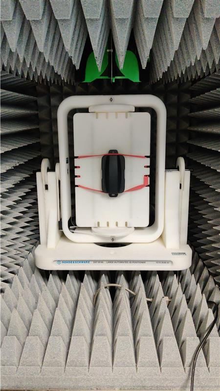
Introduction
Semtech’s LoRa Edge™ LR1110 integrates a LoRa® transceiver, a modem compatible with the
LoRaWAN® protocol, Semtech’s LoRa Cloud™ Device & Application Services, and a Wi-Fi b/g/n scanner
and a hybrid GPS/Beidou scanner. Connected devices onboard the LR1110 must support at least three
radio frequency bands:
Upper UHF bands (hereafter referred to as LoRa bands), where unlicensed LPWA connectivity is
available—anywhere from 863 to 928MHz, depending on region.
GNSS bands: 1.575.42 MHz for the GPS L1 band and 1561.098MHz for the B1 Beidou band.
2400 to 2483.5MHz for the 802.11 Wi-Fi band.
The intention of this paper is to survey the available solutions for tri-band antennas. The industry,
influenced by multiband cellular technologies such as the last generation 4G smartphones, has
developed multiband antennas, and most of these concepts are applicable to our LoRa Edge platform.
In this document, we address the following:
Pros and cons of several antenna technologies
Common traps that are inherent to wireless product design, including the do’s and don’ts
Guidance for board size, matching requirements, and antenna placement as a means of
reducing the risk of poor product design
Maximizing the chances of running successful proofs-of-concept
Optimized reference designs, including performance metrics
This is the first in a series of papers providing experimental results of the commercial, off-the-shelf
(COTS) multiband antennas we have analyzed, and is a starting point for companies wanting to integrate
the LR1110 without needing to create an expensive study regarding custom antennas.
Overall Methodology
The antenna manufacturers' websites offer baseline information for their antenna products: VSWR, gain
plots, and efficiency, all measured under specific test conditions. Most of the time the test board is
specified, showing the antenna feed point and the board size used during the experiment. Because
trackers may be size-constrained, highlighting the reasons why the antenna may not behave as specified
is critical: for instance, when the antenna is “loaded” by specific materials in its proximity, or when it is
de-tuned by a counterpoise of the wrong size.
An Evaluation of Multiband Antennas for Use with LoRa semtech.com/LoRa Page 2 of 39
Edge™ [Part One]
Technical Paper Proprietary
February 2021 Semtech
Version: 2/18/2021 10:43 AM
During this study, the guiding principles were to explain how to:
Select an antenna based on its generic characteristics, such as size and efficiency. Of course, the
focus is on tri-band antennas (wherever possible), since the LR1110 is optimized to provide
radio functions across three bands.
Simulate or evaluate the performance that an antenna is expected to have for a given set of test
cases. This test scenario can be reproduced for many antennas and tests can be compared easily
to highlight the benefits of the various models.
Measure the antenna performance dependency on board size; given that some use cases call for
extremely small, highly-integrated solutions. Our intention here is to reiterate that the laws of
physics demand a certain board size to maintain a correct efficiency, and the corollary that
antenna tuning also depends on board size.
Estimate the detuning sensitivity of the antenna. Pet trackers work in close proximity to animal
tissue, whilst cold-chain monitoring trackers operate close to metal, which has a substantial
effect on the antenna performance.
In future papers, passive antenna tests will be augmented with active antenna tests.
Our goal is to provide guidance for antenna selection, and to highlight the pitfalls related to sizing and
detuning, which are common mistakes that can lead to underwhelming performance observed in the
field or during qualification.
Why Should Antennas be as Efficient as Possible?
The bands in which LoRa operates, mostly between 863 and 928MHz, are employed around the world
for unlicensed radio devices: garage-door openers, remote controls, and domestic alarm systems, to
name a few. With the strong interest generated by the LPWAN market opportunity, traditional cellular
network carriers have invested in nationwide deployments, installing gateways with an average density
of anywhere between one gateway for ~1000 km2 (rural deployment), to one gateway for ~5 km2 (dense
urban deployment), and will densify networks in the coming years to absorb more traffic.
When rolling out a network, carriers use traditional propagation models and tools to simulate coverage,
making general assumptions such as:
Height of the gateways (base stations in cellular terminology)
Radiated power and sensitivity of the gateway
Effective radiated power of the connected IoT device
Radiated sensitivity of the IoT device
An Evaluation of Multiband Antennas for Use with LoRa semtech.com/LoRa Page 3 of 39
Edge™ [Part One]
Technical Paper Proprietary
February 2021 Semtech
Version: 2/18/2021 10:43 AM
The first two elements in the list above are well controlled: gateways are industrial-grade equipment
that can cost anything from a few hundred to a few thousand dollars, with well-placed and high-quality
antennas strapped to a fixed point on a rooftop or on a telecom tower. The propagation models,
although imperfect, benefit from decades of experience and refining from the cellular and pager
industries, and are reliable.

More importantly, to guarantee coverage, carriers make an assumption about the actual power that the
connected device radiates towards the network. In Europe, the effective radiated power (e.r.p.) is legally
limited to 25mW, and Telecomm operators will guarantee a certain coverage of territory assuming that
the actual power going out of the objects will be 25mW. Without a proper (device and) antenna design,
the coverage maps and Service Level Agreements (SLA) become irrelevant. This is why it is paramount to
get the LoRa antenna design correct from the start.

For the assisted GNSS scanner onboard Semtech’s LoRa Edge products, the performance of the GNSS
antenna is equally important. Our assisted GNSS scanner renders a sensitivity of
approximately -141dBm. The US military guarantees that, at any spot on the planet, the GPS signal will
be greater than -130dBm (https://www.gps.gov/technical/icwg/IS-GPS-200L.pdf). This represents some
margin, however, given that trackers designed for the Internet of Things (IoT) are size-constrained, not
necessarily well oriented, and typically without circular-polarized antennas facing the sky, every percent of
efficiency of the GNSS antenna is important.

Wi-Fi band efficiency is somewhat less critical; with many Wi-Fi access points (AP) usually available in
densely populated areas. Nonetheless, having a well-designed antenna ensures that as many access
points as possible are being observed.

TRIO mXTEND™ Antenna
The antenna selected for this reference design is the TRIO mXTENDTM (NN03-310) provided by Fractus
Antennas, which owns this disruptive Virtual AntennaTM technology. This antenna is the only solution
available on the market that is capable of managing three different radios (LoRa, multiband GNSS, and
Wi-Fi/Bluetooth) at the same time, inside a single antenna package. Its miniature, off-the-shelf,
multiband, high-efficiency, and tunable features make it ideal for use in combination with the LR1110.

The image below shows the TRIO mXTEND adjustable-length board.

An Evaluation of Multiband Antennas for Use with LoRa   semtech.com/LoRa                            Page 4 of 39
Edge™ [Part One]
Technical Paper                                                                                     Proprietary
February 2021                                                                                          Semtech

Version: 2/18/2021 10:43 AM

Images courtesy of Fractus Antennas
The antenna performance has been assessed with different printed circuit board (PCB) characteristics:
Adjustable length: the nominal size is 90 mm x 50 mm, in line with the ISO card standard.
Vertical lines are placed on the silkscreen, as guides to cut the board and vary its length from 54
to 126 mm. Five boards are equipped and optimized, highlighting the impact of board size on
the tuning / efficiency for each band.
Built-in module: an FMLR-1110-x-STL0 module from Miromico replaces a chip-down
implementation. This module integrates an SP3T switch, and only three antenna feed points are
available: LoRa, Wi-Fi and GNSS.
Antenna space and keep-out are implemented on the left of the board.
External matching is placed next to the antenna.
Ground is laid out under the complete board, even though there are no active parts on the right-
most half of the board; this is to emulate a large counterpoise of an IoT object.
Jumpers, JTAG interface, and positioning holes are added for the power measurement,
programming, and positioning of the device on its substrates.
Fractus Antenna Technology
Fractus Antennas owns a new and revolutionary antenna technology, called Virtual AntennaTM. Already
installed in more than 25M edge devices, this technology can replace conventional and custom antenna
An Evaluation of Multiband Antennas for Use with LoRa semtech.com/LoRa Page 5 of 39
Edge™ [Part One]
Technical Paper Proprietary
February 2021 Semtech
Version: 2/18/2021 10:43 AM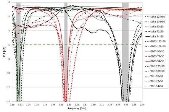
solutions by a new class of so-called antenna boosters, delivered in the form of a new range of miniature
and off-the-shelf chip antenna components. These new chip antennas are, by nature, multiband and
multipurpose, so they fit in a variety of wireless platforms to provide a wireless link for many different
communication services. By using a Virtual Antenna component, the design becomes more predictable
than custom solutions, making the entire process faster, cheaper and easier.

Common techniques for designing small multiband antennas in wireless devices are based on the use of
complex geometries, where the resonant modes of the antenna determine the frequency bands of
operation, requiring a high level of expertise for correctly shaping the antenna geometry and for
achieving acceptable behavior operating at a given frequency band.

The TRIO mXTEND chip antenna component used in this reference design is built on a glass epoxy
substrate, and belongs to this new generation of off-the-shelf antenna solutions based on Virtual
Antenna technology. It offers the advantage of being non-resonant. Its frequency-neutral characteristic
allows designers to easily select the operating frequencies according to their needs, since they are not
set by the antenna geometry, unlike conventional antenna solutions. Such an antenna supports a
number of applications and provides many benefits:

 Applications                                 Benefits
 Asset Tracking                               High efficiency
 Smart Meters                                 Large bandwidth through the same single feed point
 Smart City & Home                            Small size
 IoT Devices                                  Multiport: Three radios in one antenna component
 Modules & Sensors                            Easily tunable to the required operating regions
 Routers and Gateways                         Multiband coverage (worldwide standards)
 eHealth                                      Off-the-Shelf Standard Product (no customization is required)
                                              Automated assembly (Pick and place)
                                              Shorter Design cycle

The TRIO mXTENDTM chip antenna component offers the versatility of being usable in a single port or
multiport configuration and the flexibility of being tuned to other frequencies by simply adjusting the
matching network. The configuration for LoRa, GNSS, and Wi-Fi is illustrated here, but you can configure
it to operate with any communication standards that fit your needs

An Evaluation of Multiband Antennas for Use with LoRa   semtech.com/LoRa                                 Page 6 of 39
Edge™ [Part One]
Technical Paper                                                                                          Proprietary
February 2021                                                                                                 Semtech

Version: 2/18/2021 10:43 AM
What Makes an IoT Device Radiate Properly?
All well-designed “things” have good connectivity, and that means a better uplink (UL) and downlink
(DL) packet success rate (PSR), if all of the following conditions are satisfied:
The antenna matching is correct, ensuring that a vast majority of the incident power is radiated
by the antenna, and not reflected back to the source
The antenna efficiency is good, ideally 100 percent. This would mean that ALL the forward
power injected into the antenna (and not reflected to the source), is effectively radiated (and
not dissipated) by the antenna
The RF source supplies the right power to the antenna through its matching network, meaning
that the PA matching is correct
The effects of mismatching are as follows:
When the module is in
Transmit Mode Receive Mode
The antenna and its matching … expect a 50 Ohm RF Source. … source the module at 50
network… Ohms.
Failing this, some power will be
reflected back to the source
The module including its Source the stated output power … expect a 50 Ohm source for
matching network… (e.g. 14dBm) only if loaded by the Receiver to have a good
50 Ohms. sensitivity.
If misloaded, it may not deliver Failing this, the receiver may be
the expected RF power to the less sensitive, and some
load (antenna). mismatch loss may reduce its
performance further.
Most of the mismatch effects described in the previous table are estimated with a passive antenna
efficiency measurement, where the “efficiency” number accounts for both the mismatch loss, and the
intrinsic inefficiency of the antenna.
The graph below on the left shows the measured reflection coefficient (S11) for the reference PCB size
(90mm x 50mm). This value represents the amount of power injected by the RF module to the antenna
system that is reflected. Generally, the lower the S11, the better the antenna performance. This
parameter can be easily improved through the proper adjustment of the matching network to
effectively adapt the antenna performance to the environmental conditions. In the reference design
An Evaluation of Multiband Antennas for Use with LoRa semtech.com/LoRa Page 7 of 39
Edge™ [Part One]
Technical Paper Proprietary
February 2021 Semtech
Version: 2/18/2021 10:43 AM
presented herein, the three bands (LoRa, GNSS, and Wi-Fi) were properly matched with a reflection
coefficient below –6dB. The associated mismatch loss can be computed as follows:

Another important parameter to consider is antenna efficiency, which considers both mismatch loss and
the intrinsic radiation efficiency of the antenna. The graph below shows the radiation efficiency (Ƞr) and
the antenna efficiency (Ƞa).

 Images courtesy of Fractus Antennas

The radiation efficiency indicates the proportion of power that would be radiated to space if there were
a perfect match (mismatch loss = 0dB), whereas the antenna efficiency represents the proportion of
power actually radiated to space once mismatch losses are considered. It is computed through the
following expressions.

Image courtesy of Fractus Antennas

The following table shows Return Loss, Mismatch Loss, Radiation Efficiency, and Antenna Efficiency.

                  |S11| (dB)       |S11|           Mismatch     Rad. Eff   Rad. Eff   Ant. Eff   Ant. Eff
                                                   loss(dB)     (%)        (dB)       (%)        (dB)
 900MHz           13.0             0.22            -0.22        69.2       -1.60      65.8       -1.82
 1575MHz          20.6             0.09            -0.04        62.3       -2.06      61.7       -2.10
An Evaluation of Multiband Antennas for Use with LoRa   semtech.com/LoRa                           Page 8 of 39
Edge™ [Part One]
Technical Paper                                                                                     Proprietary
February 2021                                                                                         Semtech

Version: 2/18/2021 10:43 AM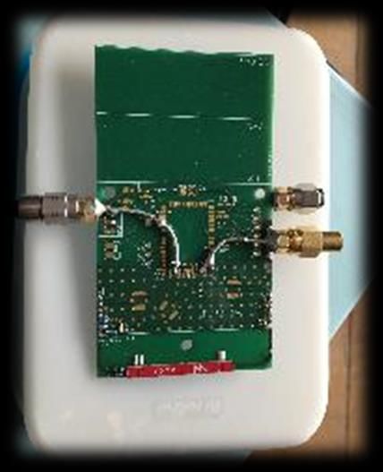
2450MHz          16.5             0.14            -0.09        63.7       -1.96   62.5        -2.04

It is important to understand that highly-efficient and non-linear power amplifiers used in LoRa devices,
specifically for the sub-GHz LoRa bands, are sensitive to their mismatch and may offer different output
power, harmonic content, and intake power consumption, when their load changes. This effect isn’t
evaluated here, as it requires an active antenna measurement method, but will be documented further
later in this series.

The image below describes a principle and is not the result of any actual measurement. It shows how a
power amplifier (PA) maintains its stated power over a certain zone of proper matching. Beyond this
zone, the PA induces some losses, is misloaded and, therefore, has a slightly degraded performance.

Mismatch Loss: Understanding the Quantities

Most of the following results are expressed in terms of reflection coefficient. They are published with a
scalar plot, with frequency on the horizontal axis, and a negative dB value on the vertical axis. The lower
the number in dB, the lower the amount of power reflected back to the source; conversely, the more
power is absorbed (and radiated) by the antenna.

The following graph represents the return loss of the TRIO mXTENDTM antenna in the Wi-Fi band, for the
standard board, with no material loading on the antenna.

An Evaluation of Multiband Antennas for Use with LoRa   semtech.com/LoRa                          Page 9 of 39
Edge™ [Part One]
Technical Paper                                                                                   Proprietary
February 2021                                                                                          Semtech

Version: 2/18/2021 10:43 AM

Less than 0.46 dB
                                             lost by mismatch

                                                                   Less than 0.05 dB
                                                                   Lost by mismatch

Just to put the numbers into perspective, the mismatch loss induced by a certain “miss” on the load
impedance, is given below:

 S11                  Quantity of power                   Quantity of power   Mismatch loss
                      Reflected back to source            forwarded to load
 0 dB                 100 %                               0 %                 -infinite
 -3 dB                50 %                                50 %                -3dB
 -6 dB                25 %                                75 %                -1.25dB
 -10 dB               10 %                                90 %                -0.46dB
 -20                  1%                                  99%                 -0.05dB

This is why the -6dB bar is displayed in the coming plots and is used as a performance indicator;
keeping -6dB of return loss, indicates that no more than 1.25dB are lost during the power transfer,
which is a reasonable target in extreme conditions, even if a perfect matching of 50Ohms with no
reflected power is desirable.

Board-size Impact: Matching and Resonance

With the virtual antenna technology, as well as with any other conventional antenna design, the board
size impacts the resonance of the object. Conversely, the antenna matching networks (in an LR1110

An Evaluation of Multiband Antennas for Use with LoRa   semtech.com/LoRa                       Page 10 of 39
Edge™ [Part One]
Technical Paper                                                                                 Proprietary
February 2021                                                                                      Semtech

Version: 2/18/2021 10:43 AM
design, there are three: LoRa, GNSS, and Wi-Fi) must be modified to ensure that the RF power delivered
by the LR1110 is effectively radiated.
As you can see in the table below, all elements of the matching network must be modified as a function
of board size, to maximize return loss and therefore good performance:
All matching networks depicted below were designed with the objective of obtaining the lowest S11 and
the highest antenna efficiency in the frequency bands required to cover the whole spectrum, from 863–
928MHz for the LoRa case, 1561–1606MHz for GNSS, and 2400–2483MHz for Wi-Fi. The PCB size affects
the performance of any antenna, not only in terms of radiation efficiency, but also in terms of
impedance. This may mean detuning, but can easily be solved by readjusting the matching networks
properly. That is why each PCB size has its own matching network to optimize the performance in the
three bands. A minimum number of components is used for this purpose, to reduce the associated
losses as much as possible. The use of high quality factor (Q) and tight tolerance components is
recommended to avoid efficiency losses in the matching network, and to ensure repeatability of the
solution. Unlike classic resonant antennas, which are specifically designed to work on certain bands,
Virtual Antenna technology can be used for all bands. The antenna element remains the same and a
readjustment of the matching networks means the antenna can work on the desired bands with the
maximum performance.
The following table shows the TRIO matching elements for each board size.
126x50 108x50 90x50 72x50 54x50
Z1 15nH 16nH 3.7nH 0Ω 4nH
Z2 2.3pF 1.9pF 10pF 4nH Open
Z3 Open Open Open Open 18pF
Z4 4.0nH 1.3nH 10pF 0Ω 12pF
Z5 Open Open 3.7nH Open 2.8nH
Z6 0Ω 0Ω 0Ω 0Ω 0Ω
Z7 6.0nH 8.4nH 8.4nH 8.4nH 8.4nH
Z8 1.6pF 1pF 1pF 1pF 1pF
Z9 0.7pF 0.5pF 8.7nH 9.1nH 8.7nH
Z10 2.2nH 1.8nH 5.6nH 5.6nH 5.6nH
Z11 8.4nH Open Open Open Open
Z12 9.1nH 10nH 7.5nH 9.1nH 8.7nH
Z13 2.3pF 2.2pF 3.2nH 5.6nH 3.5nH
Z14 4.4nH 2.3nH 1.7pF 0Ω 0Ω
Z15 28nH 28nH - - -
Z16 0.8pF 0.8pF 0.1pF 0.1pF 0.1pF
An Evaluation of Multiband Antennas for Use with LoRa semtech.com/LoRa Page 11 of 39
Edge™ [Part One]
Technical Paper Proprietary
February 2021 Semtech
Version: 2/18/2021 10:43 AMThe Notch filter indicated below is used to guarantee a certain isolation between LoRa, GNSS, and Wi-Fi.
In the same way, the first two components of the Wi-Fi branch (Z7 and Z8) are part of another notch
filter that isolates Wi-Fi from GNSS. The other components of each branch compose the matching
networks used to minimize the S11 and maximize the efficiency of the antenna.
Image courtesy of Fractus Antennas
The network diagrams below illustrate the differences among LoRaWAN, GNSS, and Wi-Fi networks.
LoRa Matching Network GNSS & Wi-Fi Matching Notch Filter
Network
Images courtesy of Fractus Antennas
The antenna tuning components must be optimized for the board size. Likewise, if the board
shape is different, these elements may have to be tweaked as well.
An Evaluation of Multiband Antennas for Use with LoRa semtech.com/LoRa Page 12 of 39
Edge™ [Part One]
Technical Paper Proprietary
February 2021 Semtech
Version: 2/18/2021 10:43 AMAs part of the free-of-charge NN Wireless Fast-Track service, Fractus can assist in designing
or optimizing your own matching network. Visit: https://www.fractusantennas.com/fast-
track-project/
The Importance of a Wideband Design
Unlicensed bands in different regions of the world are not harmonized and span from 863MHz (bottom
of the European band) to 928MHz (top of the US band). The LR1110 power amplifiers are capable of
sourcing, a carrier at any frequency across these 65MHz, at high efficiency and at the legal level of
power. As seen in the next graph, when properly tuned, the TRIO mXTENDTM antenna offers a wide
bandwidth, allowing for a single tuning for all frequency bands across the different PCB sizes.
The first graph below illustrates the return loss for 90mm Board in Air. The second graph shows the
reflection coefficient for all Board in Air sizes.
An Evaluation of Multiband Antennas for Use with LoRa semtech.com/LoRa Page 13 of 39
Edge™ [Part One]
Technical Paper Proprietary
February 2021 Semtech
Version: 2/18/2021 10:43 AMImage courtesy of Fractus Antennas
Board Size Impact: Antenna Efficiency
The ability of an antenna to radiate the power it is being fed is typically expressed in terms of efficiency,
either in dB or as a percentage:
Source power Antenna Efficiency: Antenna Efficiency: Total Radiated Power (TRP)
dBm Percent dB dBm
+ 14 100 0 14
+ 14 80 -1 13
+ 14 50 -3 11
+ 14 25 -6 8
+ 14 10 -10 4
The Total Radiated Power (TRP), shown in the table above, expresses the sum of all power radiated by
an antenna, connected to an RF source and integrated in all directions. It is not to be confused with
e.r.p., which is the observed power in one direction. Regulatory laws typically request that the peak
e.r.p. be below a certain threshold, whilst the overall performance of an omnidirectional antenna such
An Evaluation of Multiband Antennas for Use with LoRa semtech.com/LoRa Page 14 of 39
Edge™ [Part One]
Technical Paper Proprietary
February 2021 Semtech
Version: 2/18/2021 10:43 AMas the ones being measured here, is better described in terms of TRP (indeed, the orientation of most
IoT devices with regard to the network they are broadcasting to, is generally an unknown).
The graph and table below show a summary of the efficiency numbers obtained for all frequency bands
of interest, and all PCB sizes that were tested:
Image courtesy of Fractus Antennas
Ant. Eff 863MHz 928MHz AVG 1561M 1606M AVG 2400M 2500M AVG
LoRa Hz Hz GNSS Hz Hz Wi-Fi
125x50 71.5 78.1 75.7 58.8 67.7 62.0 65.3 57.2 64.8
108x50 60.6 54.2 62.6 57.1 64.3 59.4 59.9 56.7 59.4
90x50 52.4 60.9 60.6 61.1 65.8 61.9 52.9 62.4 60.5
72x50 36.5 35.9 47.3 69.5 66.9 67.3 57.6 67.3 62.4
54x50 25.1 29.6 36.4 60.2 62.1 62.4 68.5 76.7 71.9
The efficiency numbers stated in this report include mismatch losses induced by any
detuning of the antenna.
An Evaluation of Multiband Antennas for Use with LoRa semtech.com/LoRa Page 15 of 39
Edge™ [Part One]
Technical Paper Proprietary
February 2021 Semtech
Version: 2/18/2021 10:43 AMOn the Wi-Fi band, the antenna efficiency remains high, and even increases as the
board gets smaller. At these frequencies, the radiation is the contribution of the
longitudinal and transversal radiating modes of the PCB. The resonant frequency of the
longitudinal mode increases as the PCB length reduces, being closer to the Wi-Fi
operating frequencies, thus providing better performance.
However, for the LoRa bands where the wavelength is much longer (about 33 centimeters), the main
resonance is obtained on the longer board edge, which gets shorter and shorter as the board is cut.
Efficiency drops from 76 percent to about 36 percent on average, this is a 3dB hit on the antenna
performance (UL and DL) for the smaller object.
The TRIO mXTEND has the advantage of embedding three antennas in a single component, simplifying
the integration and bring-up of the IoT device.
80
70
60
50
Efficiency [%]
125x50mm
40 108x50mm
90x50mm
30
72x50mm
20 54x50mm
10
0
800 1000 1200 1400 1600 1800 2000 2200 2400 2600
Frequency [MHz]
The efficiency in the LoRa band might be optimized with the smaller board sizes by selecting an
independent antenna for that frequency band.
An Evaluation of Multiband Antennas for Use with LoRa semtech.com/LoRa Page 16 of 39
Edge™ [Part One]
Technical Paper Proprietary
February 2021 Semtech
Version: 2/18/2021 10:43 AMBoard Size Impact: Radiation Pattern
The TRIO mXTEND antenna has an omnidirectional pattern for all board sizes and frequency bands. This
is an important feature when, typically, the orientation of the device is unknown. The only exception to
this would be the GNSS antenna radiation pattern where, irrespective of the device location on the
planet, the satellite signals will always be the most powerful when the SV is “over” the device (at least in
line-of-sight conditions), meaning an elevation of 90 degrees from the horizon.
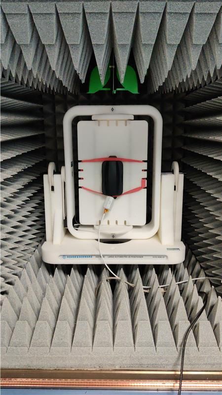
See the measured radiation patterns below for the reference PCB size (90mm x 50mm). The three main
cuts, as well as the 3D illustrations, are represented for the central frequency of each frequency band.
Image courtesy of Fractus Antennas
The following diagrams show 2D radiation plots for a 90mm board.
Frequency Band Phi 0º Phi 90º Theta 90º
866MHz
915MHz
An Evaluation of Multiband Antennas for Use with LoRa semtech.com/LoRa Page 17 of 39
Edge™ [Part One]
Technical Paper Proprietary
February 2021 Semtech
Version: 2/18/2021 10:43 AM1575MHz
2450MHz
Images courtesy of Fractus Antennas
The images below show 3D radiation plots for a 90mm board:
LoRa GNSS Wi-Fi
Image courtesy of Fractus Antennas
The main radiation pattern cuts for GNSS frequencies remain omnidirectional for all PCB sizes, so are
preferable for those devices in constant movement where the direction of the incoming waves is
unknown.
Frequency Band Phi 0º Phi 90º Theta 90º
25x50
An Evaluation of Multiband Antennas for Use with LoRa semtech.com/LoRa Page 18 of 39
Edge™ [Part One]
Technical Paper Proprietary
February 2021 Semtech
Version: 2/18/2021 10:43 AM108x50
90x50
72x50
54x50
Image courtesy of Fractus Antennas
Based on the results above, we can conclude that the TRIO mXTEND is a suitable antenna capable of
working at LoRa, GNSS and Wi-Fi bands at the same time. The larger the PCB, the higher the performance
that is expected for the LoRa band. Apart from that, any change in antenna impedance due to PCB size or
changing environmental conditions can easily be compensated through the matching network. This is one
of the advantages of Virtual Antenna technology: it can work at any standard and under different
conditions using the same antenna component, by just adjusting the matching network.
Antenna Detuning with Select Materials
IoT use-cases are diverse: Smart Home, Smart Utility, Smart Farming, Asset Tracking etc. In any of these
scenarios, the connected device is somehow anchored to an asset. Trackers may be placed on top of a
An Evaluation of Multiband Antennas for Use with LoRa semtech.com/LoRa Page 19 of 39
Edge™ [Part One]
Technical Paper Proprietary
February 2021 Semtech
Version: 2/18/2021 10:43 AMshipping container, or may be integrated on a wooden or plastic pallet. Connected thermostats may be
placed on a wall made of concrete, plaster, or on a metal beam in an industrial building. Pet trackers are
placed near animal tissue. The list goes on.
Test Setup
It is important to estimate and even better, anticipate, the material that will surround the device, to
ensure that the antenna has the best possible performance in its use case.
Tracker on a Wood Pallet Tracker on Concrete
Tracker on Metal Tracker on Body Phantom
Images courtesy of Fractus Antennas
Multiple experiments show that the underlying material and, more importantly, the distance to it, plays
a critical role in the antenna performance, both in terms of mismatch losses, and in terms of efficiency:
An Evaluation of Multiband Antennas for Use with LoRa semtech.com/LoRa Page 20 of 39
Edge™ [Part One]
Technical Paper Proprietary
February 2021 Semtech
Version: 2/18/2021 10:43 AMImage courtesy of Fractus Antennas
The following graphs show the impact of the substrate on antenna resonance per frequency band.
The vertical dotted lines indicate the extremes of the frequency bands of interest.
Legend:
Antenna in “Air”
Antenna at 15 mm distance from substrate
Antenna at 10 mm distance from substrate
Antenna at 5 mm distance from substrate
Wood – LoRa Concrete – LoRa
An Evaluation of Multiband Antennas for Use with LoRa semtech.com/LoRa Page 21 of 39
Edge™ [Part One]
Technical Paper Proprietary
February 2021 Semtech
Version: 2/18/2021 10:43 AMMetal – LoRa Body Phantom – LoRa
Measurements performed by Semtech. Image courtesy of Fractus Antennas
The S11 = -6dB performance target is displayed, guaranteeing mismatch losses of less than 1.25dB.
Wood – GNSS Concrete – GNSS
An Evaluation of Multiband Antennas for Use with LoRa semtech.com/LoRa Page 22 of 39
Edge™ [Part One]
Technical Paper Proprietary
February 2021 Semtech
Version: 2/18/2021 10:43 AMMetal – GNSS Body Phantom – GNSS
Measurements performed by Semtech. Image courtesy of Fractus Antennas
Wood – Wi-Fi Concrete – Wi-Fi
Metal – Wi-Fi Body Phantom – Wi-Fi
Measurements performed by Semtech. Image courtesy of Fractus Antennas
An Evaluation of Multiband Antennas for Use with LoRa semtech.com/LoRa Page 23 of 39
Edge™ [Part One]
Technical Paper Proprietary
February 2021 Semtech
Version: 2/18/2021 10:43 AMNote that the matching network considered for the material impact in this analysis differs from the
reference matching network selected for maximizing performance in LoRa bands. Nevertheless, the
qualitative results and conclusions extracted apply to both. Details are available in Appendix A6:
Alternative Matching for the 90mm Board.
Summary of our experimental learnings:
1. The TRIO, generally speaking, behaves well when loaded with these materials, at a distance of 5,
10 or 15mm. In the nominal case, it guarantees less than 1.25dB of mismatch losses by
maintaining the return loss below –6dB.
2. Metal loading has a dramatic impact for the LoRa and GNSS bands, at all distances. Specific
recommendations are discussed later in this paper. Metal loading has an acceptable impact to
the detuning in the Wi-Fi band.
3. Human Phantom loading has a bearable impact, except for the LoRa band when the antenna is
too close, with a 5mm gap. Increasing the gap to 10mm appears sufficient to keep a reasonable
detuning.
Detuning Results: Efficiency and Mismatch Losses
In addition to detuning, the materials in the vicinity also induce a dissipation effect which depends on the
electromagnetic characteristics of each material; some materials cause more loss than others. The
antenna efficiency has been measured for the reference board size (90mm x 50mm), placed 15mm from
the material in the vicinity, to illustrate this effect.
Image courtesy of Fractus Antennas
An Evaluation of Multiband Antennas for Use with LoRa semtech.com/LoRa Page 24 of 39
Edge™ [Part One]
Technical Paper Proprietary
February 2021 Semtech
Version: 2/18/2021 10:43 AMWhen studied at the 15mm distance, the antenna impedance is generally robust to any detuning effect,
except for the metal case in LoRa frequencies, where S11 < -3dB. In this case, a retuning to improve S11
values is possible using the virtual antenna technology to simply retune the matching network to optimize
antenna performance (which is more difficult to attain with other antenna technologies where the
operating frequencies may be determined by antenna geometry). The required bandwidths for all other
cases are always covered completely with S11 < -8dB and good antenna efficiency.
Image courtesy of Fractus Antennas
The recommendations to preserve good performance in these environments are as follows:
1. Increase the distance between the device and the material in the vicinity as much as possible.
The recommended distance depends on the material. For all the scenarios above (wood,
concrete, body phantom) except metal, a distance of 15mm is enough to guarantee very good
performance in all bands.
2. In metallic environments, align the device as closely as possible to the edge of the metal (ideally
with the antenna area protruding the metallic environment) while maximizing the distance
between the device and the metal, with a minimum distance of 25mm. See Appendix A5:
10mm Placement Tests for Metal Case for images
An Evaluation of Multiband Antennas for Use with LoRa semtech.com/LoRa Page 25 of 39
Edge™ [Part One]
Technical Paper Proprietary
February 2021 Semtech
Version: 2/18/2021 10:43 AMTRIO mXTENDTM Conclusion
The conclusions extracted from the analysis above can be summarized as follows:
1. TRIO mXTENDTM is currently the only antenna available in the market capable of handling three
radio bands (LoRa, GNSS, and Wi-Fi) inside the same single and compact antenna package, thus
reducing integration complexity.
2. TRIO mXTEND provides high performance in these three bands for the reference PCB size
(90mm x 50mm). As a general rule, the bigger the PCB, the better the performance for LoRa
channels.
3. The performance starts to degrade as the PCB shrinks, such as in the lower frequency bands
where the board dimension is much lower than the wavelength, as happens with other
conventional antenna solutions. The advantage of the TRIO mXTEND is that the detuning caused
by PCB size reduction can be compensated by matching network adjustment, meaning that no
customization of the antenna is needed. This adjustment is more difficult to attain with
conventional antenna solutions where operating frequencies are determined by the antenna
geometry.
4. The radiation patterns are omnidirectional in all cases, which is preferable for devices in
constant movement, where the direction of the incoming waves is unknown.
5. The materials in the vicinity affect the radiation from two perspectives: antenna detuning and
power absorption.
6. The TRIO mXTEND is robust in terms of detuning by the proximity of materials in the vicinity.
The largest impact on detuning occurs in metallic environments, followed by human body
interactions.
7. If a detuning occurs, it can be compensated by adjusting the matching network.
8. As a general rule, the larger the distance from the material in the vicinity, the better the
performance. For the most critical case, the metal scenario, place the device as closely as
possible to the edge of the metallic section, at a minimum distance of 25 mm. Even better
performance is expected if the antenna area protrudes the metallic area.
An Evaluation of Multiband Antennas for Use with LoRa semtech.com/LoRa Page 26 of 39
Edge™ [Part One]
Technical Paper Proprietary
February 2021 Semtech
Version: 2/18/2021 10:43 AMAppendices A1: References: Phantom Solution Recipes and Matching Detuning experiments were run at home (due to the Covid-19 pandemic), in a do-it-yourself (DIY) fashion. For use cases such as pet or cattle tracking, the detuning induced by human tissue becomes an important performance factor, therefore a sucrose-based phantom solution was prepared. The National Institute of Health in Maryland has published a phantom solution calculator, for both sucrose and PVT- based recipes. It is available on: https://amri.ninds.nih.gov/cgi-bin/phantomrecipe. The resonant frequency of human tissues is tabulated in this study: https://www.emf- portal.org/en/cms/page/home/effects/radio-frequency The conductivity is tabulated in this study: https://drum.lib.umd.edu/bitstream/handle/1903/3532/umi- umd-3365.pdf on Table 2.3 on Page 10. An extract is here: The following body phantom solution was prepared and boiled for a couple of minutes: Compound Weight Salt (NaCl) 31.5 g Sugar 245.7 g An Evaluation of Multiband Antennas for Use with LoRa semtech.com/LoRa Page 27 of 39 Edge™ [Part One] Technical Paper Proprietary February 2021 Semtech Version: 2/18/2021 10:43 AM
Agar                  2.25 g

 Benzoic Acid          0.15 g

 Distilled water       150 g

Voilà!

It is important to confirm that the RF characteristics of the solution match those that occur when the
antenna is close to an actual body. To this end, the 90mm board was alternately placed 10mm above the
phantom solution (poured into a household plastic box, whose RF characteristics are experimentally
verified to be negligible), then on my thigh. The reflection coefficient was measured at all three
frequencies of interest:

 On phantom solution                                       On body (thigh)

An Evaluation of Multiband Antennas for Use with LoRa   semtech.com/LoRa                    Page 28 of 39
Edge™ [Part One]
Technical Paper                                                                              Proprietary
February 2021                                                                                   Semtech

Version: 2/18/2021 10:43 AM
LoRa
                                                                      Body (Pink)
                                                                 Phantom Solution (Red)

                                                                         GNSS
                                                                       Body (Red)
                                                                 Phantom Solution (Pink)

                                                                         Wi-Fi
                                                                       Body (Red)
                                                                 Phantom Solution (Pink)

These results indicate a reasonable fit of the recipe for all three frequency bands of interest.
An Evaluation of Multiband Antennas for Use with LoRa   semtech.com/LoRa                           Page 29 of 39
Edge™ [Part One]
Technical Paper                                                                                     Proprietary
February 2021                                                                                          Semtech

Version: 2/18/2021 10:43 AM
A2: Active Antenna Testing Validates Passive Antenna Testing
As described above, in the section What Makes an IoT Device Radiate Properly?, improper load on an
integrated power amplifier may reduce its performance. Hence, the natural step at the end of the design
cycle is to run “Active Antenna Tests”.
In a passive antenna test, the wireless transceiver used in the IoT device is replaced with lab equipment
such as a signal generator:
Passive Antenna Test
Representation:
Coax to Test Equipment
This method, applied with all the relevant caution, gives good results, and a proper estimation of the
antenna efficiency is possible.
However, when the objects to be measured become smaller, the test harness (sourcing equipment and
its cable, temporarily attached to the IoT device) may significantly impact the results. On top of this, the
effect of mismatch on the actual PA is not measured.
In an active antenna test, there is no test harness connected to the device. Instead, the active module
on the test board, here the FMLR-1110-X-L07 module, generates the carrier used to measure the
antenna performance in the chamber. Consequently, the results obtained in terms of efficiency, e.r.p.,
and radiation pattern will be 100% representative of the actual use of the device in the application.
An Evaluation of Multiband Antennas for Use with LoRa semtech.com/LoRa Page 30 of 39
Edge™ [Part One]
Technical Paper Proprietary
February 2021 Semtech
Version: 2/18/2021 10:43 AMActive Antenna Test
Representation:
Fully-Active Device
Although this paper does not cover this aspect, we are hoping to back-up these measurements with
active antenna tests in some of the many conditions covered in this document.
An Evaluation of Multiband Antennas for Use with LoRa semtech.com/LoRa Page 31 of 39
Edge™ [Part One]
Technical Paper Proprietary
February 2021 Semtech
Version: 2/18/2021 10:43 AMA3: Results Obtained by Simulation Fractus Antennas offers a free simulation service called Wireless Fastrack. This service consists of providing a proof-of-concept to the IoT designers, to give them an order of magnitude of the expected antenna performance for their PCB size. The service guides them in the proof phases of their projects to get the most efficient antenna designs that meet their expectations. It also includes the most appropriate Virtual Antenna component selection, together with design recommendations for its appropriate integration, recommended matching network topology, and bill of materials, as well as estimated antenna performance. Illustrated below are the results obtained for the reference case study above (PCB of 90mm x 50mm) using the Wireless Fastrack service. Both simulations and measurements are in agreement for LoRa and GNSS. In the Wi-Fi bands some differences appear, mainly because, at these high frequencies any element can affect performance, this is the case for the cables and SMA connectors not modelled during the simulation process, but present in the measurement set-up. Nevertheless, the level of agreement is still good and provides a very fast preliminary analysis to have an order of magnitude of the expected performance in your device. The service is provided in 24 hours from the reception of the Wireless Fastrack request (subject to terms and conditions). Images courtesy of Fractus Antennas An Evaluation of Multiband Antennas for Use with LoRa semtech.com/LoRa Page 32 of 39 Edge™ [Part One] Technical Paper Proprietary February 2021 Semtech Version: 2/18/2021 10:43 AM
Image courtesy of Fractus Antennas

Image courtesy of Fractus Antennas

An Evaluation of Multiband Antennas for Use with LoRa   semtech.com/LoRa   Page 33 of 39
Edge™ [Part One]
Technical Paper                                                             Proprietary
February 2021                                                                  Semtech

Version: 2/18/2021 10:43 AM
Image courtesy of Fractus Antennas

The table below shows the comparisons for simulated and measured results for the frequencies
indicated.

                863           928        LoRa           1561    1606       GNSS   2400   2500   Wi-Fi
                MHz           MHz        AVG            MHz     MHz        AVG    MHz    MHz    AVG
 Sim            62.9          60.5       66.7           65.8    61.6       66.8   77.6   80.2   80.0
 Meas           52.4          60.9       60.6           61.1    65.8       61.9   52.9   62.4   60.5

An Evaluation of Multiband Antennas for Use with LoRa   semtech.com/LoRa                        Page 34 of 39
Edge™ [Part One]
Technical Paper                                                                                  Proprietary
February 2021                                                                                       Semtech

Version: 2/18/2021 10:43 AM
A4: Passive Element Part Numbers The following capacitors and inductors, from Murata, were used during the experiments: L and C Commercial References: Value Part Number Value Part Number Value Part Number Inductor Inductor Inductor 28nH LQW18AN28NG80 4.4nH LQW15AN4N4G80 34nH LQW18AN34NG80 16nH LQW18AN16NG80 4.0nH LQW15AN4N0G80 11nH LQW18AN11NG80 15nH LQW18AN15NG80 3.7nH LQW15AN3N7G80 9.1nH LQW18AN9N1G80 10nH LQW18AN10NG10 3.5nH LQW15AN3N5G80 8.4nH LQW18AN8N4G80 9.1nH LQW18AN9N1G80 3.2nH LQW15AN3N2B00 5.0nH LQW15AN5N0B80 8.7nH LQW18AN8N7G80 2.8nH LQW15AN2N8G80 2.5nH LQW15AN2N5G80 8.4nH LQW18AN8N4G80 2.3nH LQW15AN2N3G80 2.2nH LQW15AN2N2G80 7.5nH LQW18AN7N5C80 2.2nH LQW15AN2N2C10 34nH LQW18AN34NG80 6.0nH LQW5AN6N0B80 1.8nH LQW15AN1N8C00 11nH LQW18AN11NG80 5.6nH LQW15AN5N6C10 1.3nH LQW15AN1N3C10 0.8pF GJM1555C1HR80WB01 2.1pF GJM1555C1H2R1WB01 1pF GJM1555C1H1R0WB01 8pF GJM1555C1H8R0WB01 15pF GJM1555C1H150FB01 9.1pF GJM1555C1H9R1WB01 An Evaluation of Multiband Antennas for Use with LoRa semtech.com/LoRa Page 35 of 39 Edge™ [Part One] Technical Paper Proprietary February 2021 Semtech Version: 2/18/2021 10:43 AM
A5: 10mm Placement Tests for Metal Case

Although metal impacts performance, we can minimize this impact if the PCB is placed in the corner of
the metal surface. In this experiment the PCB is 10 mm from the metal and the matching network used
is the one shown the Board-size Impact: Matching and Resonance section. Results would be even better
if the distance between the PCB and the metal surface was greater.

                      PCB in the middle                                    PCB on the corner
Images courtesy of Fractus Antennas

The following graph and table show the measured efficiency of the antennas for each of these
placements.

An Evaluation of Multiband Antennas for Use with LoRa   semtech.com/LoRa                       Page 36 of 39
Edge™ [Part One]
Technical Paper                                                                                 Proprietary
February 2021                                                                                      Semtech

Version: 2/18/2021 10:43 AM
Images courtesy of Fractus Antennas
Ant. Eff 863 928 AVG 1561 1606 AVG 2400 2500 AVG
MHz MHz LoRa MHz MHz GNSS MHz MHz Wi-Fi
PCB in the 11.2 12.2 13.3 52.4 43.8 48.8 35.2 48.8 42.4
middle
PCB on the 15.2 21.4 22.4 53.8 62.4 59.3 50.7 65.2 57.9
corner
An Evaluation of Multiband Antennas for Use with LoRa semtech.com/LoRa Page 37 of 39
Edge™ [Part One]
Technical Paper Proprietary
February 2021 Semtech
Version: 2/18/2021 10:43 AMA6: Alternative Matching for the 90mm Board
The following matching was used for the detuning experiments on the 90 mm board:
LoRa Matching Network GNSS & Wi-Fi Matching Notch Filter
Network
Z1 Z2 Z3 Z4 Z5 Z6 Z7 Z8 Z9 Z10 Z11 Z12 Z13 Z14 Z15 Z16
90x50 8.4nH 15pF 2.5nH 8pF 5nH 0Ω 8.4nH 1pF 9.1nH 2.2nH OPEN 11nH 2.1pF 2.2nH 0.8pF 34nH
Images courtesy of Fractus Antennas
An Evaluation of Multiband Antennas for Use with LoRa semtech.com/LoRa Page 38 of 39
Edge™ [Part One]
Technical Paper Proprietary
February 2021 Semtech
Version: 2/18/2021 10:43 AMImportant Notice
Information relating to this product and the application or design described herein is believed to be reliable, however such
information is provided as a guide only and Semtech assumes no liability for any errors in this document, or for the
application or design described herein. Semtech reserves the right to make changes to the product or this document at any
time without notice. Buyers should obtain the latest relevant information before placing order and should verify that such
information is current and complete. Semtech warrants performance of its products to the specifications applicable at the
time of sale, and all sales are made in accordance with Semtech's standard terms and conditions of sale.
SEMTECH PRODUCTS ARE NOT DESIGNED, INTENDED, AUTHORIZED OR WARRANTED TO BE SUITABLE FOR USE IN LIFE-
SUPPORT APPLICATIONS, DEVICES OR SYSTEMS, OR IN NUCLEAR APPLICATIONS IN WHICH THE FAILURE COULD BE
REASONABLY EXPECTED TO RESULT IN PERSONAL INJURY, LOSS OF LIFE OR SEVERE PROPERTY OR ENVIRONMENTAL
DAMAGE. INCLUSION OF SEMTECH PRODUCTS IN SUCH APPLICATIONS IS UNDERSTOOD TO BE UNDERTAKEN SOLELY AT THE
CUSTOMER'S OWN RISK. Should a customer purchase or use Semtech products for any such unauthorized application, the
consumer shall indemnify and hold Semtech and its officers, employees, subsidiaries, affiliates, and distributors harmless
against all claims, costs, damages and attorney fees which could arise.
The Semtech name and logo are registered trademarks of the Semtech Corporation. All other trademarks and trade names
mentioned may be marks and names of Semtech or their respective companies. Semtech reserves the right to make changes
to, or discontinue any products described in this document without further notice. Semtech makes no warranty,
representation guarantee, express or implied, regarding the suitability of its products for any particular purpose. All rights
reserved.
©Semtech 2020
Contact Information
Semtech Corporation
200 Flynn Road, Camarillo, CA 93012
Phone: (805) 498-2111, Fax: (805) 498-3804
www.semtech.com
An Evaluation of Multiband Antennas for Use with LoRa semtech.com/LoRa Page 39 of 39
Edge™ [Part One]
Technical Paper Proprietary
February 2021 Semtech
Version: 2/18/2021 10:43 AMYou can also read