Analysis on the Circuit Design of Fire Alarm - IOPscience
←
→
Page content transcription
If your browser does not render page correctly, please read the page content below

Journal of Physics: Conference Series

PAPER • OPEN ACCESS

Analysis on the Circuit Design of Fire Alarm
To cite this article: Shaoxuan Kang 2021 J. Phys.: Conf. Ser. 1920 012022

View the article online for updates and enhancements.

                              This content was downloaded from IP address 46.4.80.155 on 16/08/2021 at 02:11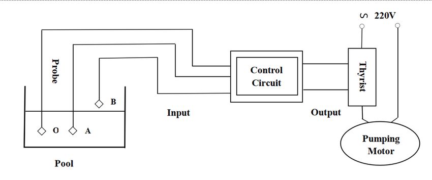
EEICE 2021                                                                                                      IOP Publishing
Journal of Physics: Conference Series                         1920 (2021) 012022          doi:10.1088/1742-6596/1920/1/012022

Analysis on the Circuit Design of Fire Alarm

                     Shaoxuan Kang1
                     1
                         Beijing No.80 High School, Beijing 100000, China
                     *Corresponding author’s e-mail: angela@cas-harbour.org

                     Abstract. In the large airtight cinema and school, there are a lot of people in public places, thus
                     the fire safety problems always attach great importance to everyone. The appearance of fire
                     alarms can definitely help audience who are immersed in watching movies and students who are
                     listening to the teachers carefully to remind them of a fire, so they can leave the scene in time
                     and reduce property losses. This paper will take the fire alarm circuit as an example to realize
                     the combined logic circuit by using various integrated circuits of different scales. This design is
                     very flexible, effective and operable. In the actual process of use, the appropriate scheme can be
                     selected according to the design requirements and the resource of the device. The object of study
                     is a logic circuit, which is composed of an integration gate or a medium scale synthesizer. The
                     experimental methods include practical ideas, application of Boolean logic principles, and
                     sampling of data from others through the Internet, which are mentioned at the end of the paper.
                     The conclusion is that abstract logic can be used step by step to design a practical and effective
                     circuit diagram.

1. Introduction
After taking the online course of logic circuit, the author was very curious about the principle of Boolean
logic, so close attention to the news was paid in real life. When the author knew that a recent fire had
temporarily shut down a movie theater that the author had been to, the author began to think of ways to
reduce the damage caused by a fire alarm, which is a common tool in public places that could alert
people to impending disaster. Therefore, the author began to think about the circuit structure of fire
alarm, the working principle and the space for improvement in design [1]. Some simple circuit templates
of fire alarm based on the information of fire alarm on the Internet were constructed, with some of its
existing circuit design adding the author’s own understanding, in order to further understand its structure
and generate some ideas for its future transformation. The study not only lets the author deepen the
understanding of logic circuit, but also further sparks his interest in the application of it. It is hoped that
one day in the future a better fire alarm can be designed. For instance, earthquake alarm security is
closely linked with people, and small instruments could help reduce the loss for creating a more safe
and stable living environment.
    An ideal, nearly perfect fire alarm should be able to quickly perceive or predict the danger and make
effective feedback very quickly. In order to ensure the two requirements of "fast" and "sensitive", a very
fast information transmission circuit is needed, which is the reason that the author chooses the
combinatorial logic circuit as my first choice [2]. The characteristic of combinatorial logic circuits is
that the output at any time depends only on the input at that time, independent of the original state of
the circuit. This feature makes it have an efficient timeliness, which can be in a variety of emergency
occasions (especially in the case of sudden disaster) in the early warning, reduce the loss of society. At
present, the design structures of combinatorial logic circuits are still needed to be improved. Most
combinatorial logic circuits used in reality are very complex, and a large part of them need to be
              Content from this work may be used under the terms of the Creative Commons Attribution 3.0 licence. Any further distribution
              of this work must maintain attribution to the author(s) and the title of the work, journal citation and DOI.
Published under licence by IOP Publishing Ltd                          1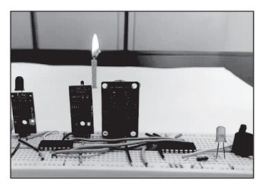
EEICE 2021                                                                                     IOP Publishing
Journal of Physics: Conference Series            1920 (2021) 012022      doi:10.1088/1742-6596/1920/1/012022

simplified. In addition, "crisis" sensors, for example, smoke sensors and temperature sensors in a fire,
need a lot of technological progress to ensure that they do not fail or "lie". This may require advances
in fields other than electricity, such as chemistry, heat science and materials science.

2. Analysis of the Circuit
Fires are often accompanied by the spread of flames, dense smoke and the threat of high temperature.
The characteristics of these three factors can be detected by flame sensor, smoke sensor and temperature
sensor respectively. At the same time, in order to prevent the false alarm of the alarm from affecting
people's daily life, only when two or more than two sensors detect abnormal situation, the circuit will
produce an alarm signal [3].
   Since the circuit is composed of three main sensors, the author needs to apply the combinational
logic circuit to realize the normal operation of the circuit. As combinational logic circuit is mostly
composed of gate circuit and medium scale integrated chip, and it is necessary to consider the specific
design requirements of reality and the resource of devices. In the following experiments, these two
devices will be mainly used for design.
                                         Table 1 The “Truth table”

    Firstly, according to the abstracted 3-2-1 model (three sensors, alarm will only go off when two or
more detect abnormalities), all the combinations of situations that will happen are listed. Here, A stands
for flame sensor, B for smoke sensor, C for temperature sensor, and D for alarm. Among them, A, B, C
are inputs and D is output. The input "1" represents detection of abnormalities and the input "0"
represents no abnormalities. The output "1" represents alarm signal generation, and the output "0"
represents no alarm signal generation, which are shown in the table above.
    From table 1, the author can get the expression D= AB'C+ABC'+A'BC+ABC [4]. And with this
expression, the logical diagram corresponded to the table above can be drawn.

                                        Figure 1. Electrical Circuit 1

                                                       2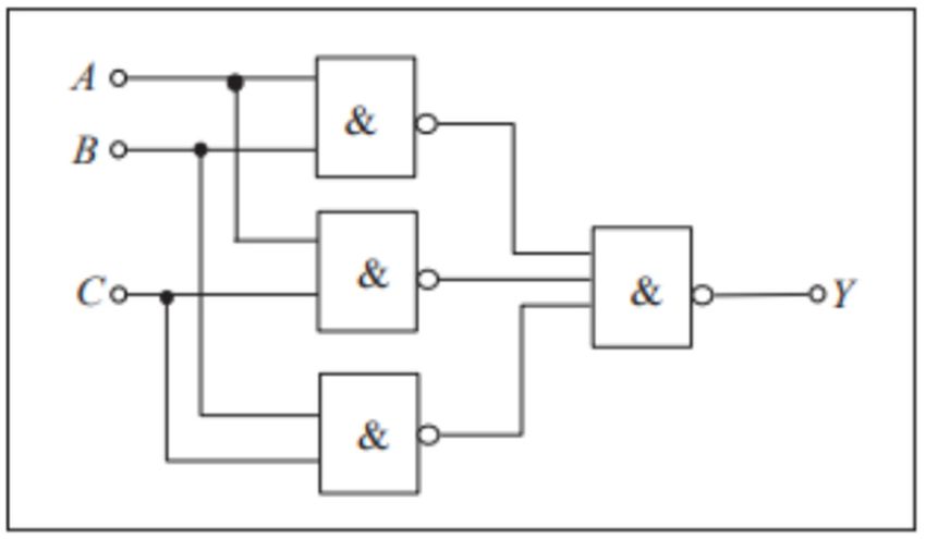
EEICE 2021                                                                                 IOP Publishing
Journal of Physics: Conference Series          1920 (2021) 012022    doi:10.1088/1742-6596/1920/1/012022

3. NAND Gate
There is a method which is to use and NAND gate. In real life, NAND gate is very common, because it
is cheap and fast, with strong load capacity. The following figure shows that the logic is converted into
NAND gate form [5].

                                  Figure 2. Electrical Circuit 2
   Then a common decipher is needed (Y means D stated before which is the output alarm):

                                   Figure 3. Simple Common Decipher
Next, the full one looks like the diagram below [6]:

                                  Figure 4. Full Common Decipher [8]
   Based on the figures above, the logic diagram is realized by gate circuit and medium scale integrated
device respectively. With the logic diagram, the circuit can be built according to the actual components,
where A, B and C are respectively connected with flame sensor, smoke sensor and temperature sensor.
Light emitting diodes and buzzers can be used as the output to detect fire, to realize sound and light
alarm, and also to connect subsequent circuits according to needs, which is very practical. The effect is
obvious and the output is stable and the physical diagram of the circuit is shown in the following figure.

                                                     3
EEICE 2021 IOP Publishing
Journal of Physics: Conference Series 1920 (2021) 012022 doi:10.1088/1742-6596/1920/1/012022
Figure 5. The model
4. Application of Combinational Logic Circuits
There are also many real-world applications of combinational logic circuits. The following pumping
motor is one typical example of it.
Figure 6. Automatic control diagram of pumping motor [6]
When there is no water in the pool, the two detection heads of A and B are not connected with the O
probe, then the input of A and B are at A low level. At this time, no matter what the original state of the
control circuit is, the output is at A high level to control the SCR conduction, so that the motor is
connected to the power supply for pumping [7]. When the water in the pool is immersed in probe A but
not probe B, because the water contains A small amount of electrolyte, it will conduct electricity, so A
and O are connected, A is the high level, B is the low level. At this time, the control circuit will analyze
whether the pump is in the "pumping" state or in the "non-pumping" state. If it is "pumping" state, then
the control circuit output high level, continue pumping; If it is in the "non-pumping" state, then output
low level, no pumping. When the three probes A, B and O in the pool are immersed in water, the probes
A and B are connected with the probes O, A and B are high level. At this time, no matter what the
original state of the control circuit is, the output is low level, so that the SCR stops and the control motor
stops pumping.
5. Conclusion
Combinational logic circuits can be designed by implementation of gate circuits and medium scale
integrated chips. Both of them require logical abstraction first and logical abstraction of column true
value table. After that, writing logical expression from truth table, and drawing logical graph from
logical expression should be followed. What needs to be distinguished is that, when using gate circuit
design, the logic formula generally needs to be simplified, and the logic diagram is drawn from the
simplified results. But when using the medium scale integration chip design, it does not need logic
4EEICE 2021 IOP Publishing
Journal of Physics: Conference Series 1920 (2021) 012022 doi:10.1088/1742-6596/1920/1/012022
formula or logic diagram. To simplify, the emphasis should be on deciding which medium scale chip
should be selected, and also asking the actual question. The logical expression of the question is
transformed into the response expression of the selected scale integration chip.
The ways of choosing the design methods of different types of medium scale integrated chips are also
different. Comparatively, the gate circuit price is cheap and the design is flexible, which does not suffer
the integrated circuit power. However, the scale integrated circuit function is more powerful and has
fewer input variables which can be the advantage of it. On the contrary, it also has certain drawbacks.
They have their own different advantages and disadvantages in the actual use of the need to choose the
appropriate scheme according to the design requirements and device resources.
Acknowledgments
I would like to express my gratitude to Krishnendu, a professor of electrical science in Duke University,
and Aiming Guo, a teaching assistant, for their guidance and support. I would also like to express my
gratitude to Wanfang Data Platform for providing part of the charts. Without your help, I would not
have been able to complete my first academic paper in my life, and I would not have been able to
demonstrate my love for analog circuits. Finally, this article may have some syntax problems or data
deviation, I hope you understand.
References
[1] Jiang L., Wu Y. Q. (2017) Based on traffic design of combinational logic circuit fault alarm system
[J]. Journal of electronic testing, (2):37-38. Doi: 10.3969 / j.i SSN. 1000-8519.2017.02.018.
[2] Wan N., (2008) A method of combinational logic circuit design [J]. Journal of modern electronic
technology, 31 (6):6-7, 11. doi: 10.3969 / j.i SSN. 1004-373 - x. 2008.06.003.
[3] Hu J. (2015) Design Method of Combinational Logic Circuit [J]. Shandong Industrial Technology,
(4):152-152.
[4] Wang D. H. (1996) Design method of Combinational Logic Circuit [J]. Journal of Lingling Normal
University, pp.71-73.
[5] Liu L. (2001) [J]. Journal of combinational logic circuit design of chaohu college journal, 3(3):90-
92. doi: 10.3969 / j.i SSN. 1672-2868.2001.03.033.
[6] Zhang H. (2020) Baidu Scholar, doi: 10.3969/j.issn.1006-4311.2013.16.033
[7] Chen J. H. (2013) The electrician foundation Nanjing machinery college, (2):63-66.
[8] Chen D. (2019) A continuous transonic wind Design of total pressure control method, Experimental
fluid mechanics, (12):65-71.
5You can also read