RFS COMPACT DIN RAIL MOUNTING TEMPERATURE CONTROLLER
←
→
Page content transcription
If your browser does not render page correctly, please read the page content below
RFS
COMPACT DIN RAIL MOUNTING TEMPERATURE CONTROLLER

- SMART TUNE- PID CONTROL
- UNIVERSAL INPUT, TC, 3 WIRE RTD AND LINEAR mA, mV, V
- PROCESS, BAND, DEVIATION AND CONTROL FAULT ALARMS
- SOFT START POWER LIMITER
- 3 RELAY/ SSR OUTPUTS
- 1 ISOLATED LOGIC INPUT
- CT INPUT - LOAD CURRENT MONITORING
- RS 485 MODBUS SERIAL COMMUNICATION
- MODULAR BUSSED INTERCONNECTION
- OPC BASED GRAPHICAL CONFIGURATION SOFTWARE
RFS
OVERVIEW
Designed to offer outstanding control performance and provide a comprehensive solution
for a wide variety of applications such as; food processing, plastic manufacturing, and
process applications requiring heat/cool control and process protection alarms in a compact
DIN rail mounting package.
Universal-thermocouple or RTD input coupled with a responsive SMART auto-tuning PID
control algorithm that is equipped with special functions including soft start and non linear
cooling. A complete set of process protection alarm function; high and low limit, band and
deviation are included.
Modular bussed interconnection allows simultaneous connection of all common
instrument elements:(power supply, serial interface, logic input and open collector output
for common alarms).
The alarm-logic input expansion unit RFS-AL makes use of the modular bussed
interconnection to provide additional I/O capacity.
SYNCHRONISED PRE-HEATING
This function eliminates differential heating during machine start up due to differing heating rates of individual heaters in applications such as
extruders and injection tool hot runner control.
It operates by synchronising the set-point ramp rate of all heating zones within a controlled group by "holding back" the ramping set-point of
these instruments using the individual loop band alarm functions. The common alarm output and isolated logic input functions are used to
achieve this.
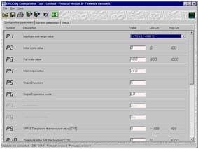
PC INTERFACE PORT + OPC BASED CONFIGURATION SOFTWARE
The integrated configuration port uses special software and an adaptor allowing:
1. Easy configuration of the instrument, with descriptions of the parameters and of the
relative limits.
2. Computer storage of the complete configuration enabling the same configuration to be
copied to other RFS units.
3. Copying and cloning of configuration to a new instrument.
4. The configuration interface port may be used in both configuration and operating modes.
to monitor the process during set up.RFS PROCESS PROTECTION ALARMS Process (high or low limit), Band and Deviation alarm outputs are available with the additional flexibility of latching and masking functions until the process variable reaches the alarm threshold. Band and Deviation alarms are also masked after a set point change until the process variable reaches the alarm threshold. The alarm latching function holds the alarm on until it is acknowledged. SMART TUNING Automatically adjusts the PID parameters according to the process dynamics. An important characteristic of the ERO Electronic continuous self tuning algorithm is its ability to optimise control parameters without injecting any artificial disturbances into the system. SEQUENTIAL ADDRESSES (MODBUS) FOR COMMONLY ACCESSED PARAMETERS To maximise the data transfer rates between the RFS and the host supervisory system important operating parameters are grouped. Digital status information is transferred as data words to increase efficiency. The RFS is able to communicate relevant parameter information with a single data request, not a series of separate address operations. START UP ENERGY MANAGEMENT To reduce the maximum electrical loading at machine start-up, during full power conditions, the sequence of the RFS control outputs are scheduled according to the selected instrument ModBus address. This facility significantly reduces maximum machine start-up current requirements and offers potential savings in electrical installation capacity and cabling specification requirements. COMMUNICATION AVAILABILITY OF I/O All RFS I/O may be read directly over the ModBus communication interface by the host supervisory system. Additionally, the communication host may write to RFS outputs that are not assigned as alarm or status functions. This facility expands available PLC and host supervisory system I/O, simplifies machine troubleshooting and provides the possibility to perform remote diagnostics. OFD FUNCTION - OUTPUT FAILURE DETECTION (optional) Using the CT input, the output failure detection function monitors the current in the load driven by the output 1. Load and actuator protection is provided in the following way: - During the ON period of the output, the instrument measures the current through the load and it generates an alarm condition if this current is lower than a pre-programmed threshold. A low current shows a partial or total break down of the load or actuator SSR. - During the OFF period of the output, the instrument measures the leakage current through the load and it generates an alarm condition when this current is higher than a pre-programmed threshold value. A high leakage current shows a short circuit of the actuator.
RFS
  PRODUCT SPECIFICATION

                                Case:          PC/ABS grey colour
           Self-extinguishing degree:          V0 according to UL 746C.
                     Front protection:         IP 20
                         Dimensions:           131 x 117 x 22.5mm
                              Weight:          250g max
                        Power supply:          switching 24V AC/DC (±10% of the nominal value)
                 Power consumption:            6VA
                           Insulation:         reinforced insulation is guaranteed between the supply input and the instrument inputs and outputs
            Common mode rejection:             120dB @ 50/60Hz.
             Normal mode rejection:            60dB @ 50/60Hz.
                         EMC/Safety:           this instrument is certified CE. It complies with regulations 89/336/EEC
                                               (harmonized reference standard EN-50081-2 and EN-50082-2) and 73/23/EEC e 93/68/EEC
                                               (harmonized reference standard EN 61010-1).
                          Installation:        DIN rail mounting.
                Installation category:         II.
                      Sampling time:           - 250mSec for linear inputs
                                               - 500mSec for TC or RTD inputs
                           Accuracy:           ± 0.2% f.s.v. @ 25°C with nominal supply.
              Operative temperature:           0 to +50°C.
               Storage temperature:            -20 to +70°C.
                          Humidity:            20% to 85% non condensing RH

  MEASUREMENT INPUTS
  All inputs are configurable and calibrated in the factory.                                                   Standard scale table
                                                                                                               TC type              °C             °F
                                                                                                               L               0/400.0         0/1650
  Thermocouple input                                                                                           L                 0/900
                                                                                                               J          -100.0/400.0       -150/1830
                              Sensor break:    open circuit sensor break detection.                            J            -100/1000
                  Cold joint compensation:     automatic compensation for temperature between 0 and 50 °C.     K          -100.0/400.0       -150/2500
                                                                                                               K            -100/1370
          Error of cold joint compensation:    0.1°C/°C.                                                       N            -100/1400        -150/2550
                          Input Impedance:     > 1MΩ.                                                          R                0/1760          0/3200
                                                                                                               S                0/1760          0/3200
                                Calibration:   - according to IEC 584-1                                        T          -200.0/400.0        -330/750
                                               - DIN 43710-1977 for TC type L
RFS
RTD Input Standard scale table
Type: 3 wire Pt 100 RTD °C °F
Calibration: according to DIN 43760 PT 100 -200.0/400.0 -200.0/400.0
3 wire -200/800 -330/1470
Measure current: 130µA.
Line resistance: automatic compensation up to 20Ω/wire with
non measurable error
Engineering units: programmable °C or °F
Sensor break: indication of the breaking of the sensor or of one or more wires.
Indication of a short-circuit when sensor resistance is less than 15Ω.
Linear inputs (mA - V)
Standard scale table
Input Impedance
Scale field: programmable from keyboard -1999 to 4000. 0 - 20 mA < 5Ω
Decimal point: programmable in any position. 4 - 20 mA < 5Ω
0 - 60 mV > 1 MΩ
12 - 60 mV > 1 MΩ
LOGIC INPUT
Logic Input Function: selection of the operative set point (SP or SP2) or of the temporary block of the execution of the
ramp on the set point
Type: dry contact
exititation 8V, 8mA
Insulation: functional insulation
Insulation voltage: 50Vrms.
CURRENT TRANSFORMER INPUT
Input current: 50mA - 50/60Hz
Full scale measurement range: 0-10 A, 0- 100A (configurable)
Resolution: 0-20A: 0.1A.
21-100A: 1A.
Programmable output state: NO or NC- relay control output.
1 or 0 logic level - SSR control output.
Minimum period length: On and Off: 400mSec..
OUTPUTS
Output 1 and 2 - SSR
Function: regulating output
Type: non insulated
Logic level 1:
- max.27V DC @ 1mA
- min.14V DC @ 20mA
Logic level 0: < 0.5VRFS
Relay Type
Output 1
Function: regulating output
Type: SPST
Contact load: 3A @ 250V AC max. on resistive load
Output 2
Function: regulating output or alarm
Type: relay with SPST contact
Contact load: 3A @ 250V AC max. on resistive load
Output 3
Function: alarm output
Type: relay with SPDT contact.
Contact load: 3A @ 250V AC max. on resistive load
Output 4
Function: group alarm output (common output)
Type: open collector
Contact load: max 20mA @ 48V.
CONTROL ACTION
Type: one (heating) or two (heating/cooling)control outputs.
Output action: proportional time.
Control actions: PI + PID + SMART + ON/OFF.
Proportional band: - 1.0% to 100.0% of the input range width for processes with one regulating element.
- 1.5% to 100.0% of the input range width for processes with two regulating elements.
Selecting PB = 0 the regulation becomes ON/OFF kind.
Hysteresis (for control action
of ON/OFF): programmable from 0.1% to 10.0% of the input field width.
Integral time: programmable from 1 second to 20 minutes or excluded.
Time of derivative action: programmable from 1 second to 10 minutes or excluded.
Offset of the integral action: - for one regulating element (heating), the offset is programmable from 0 to 100% of the output range.
- for two regulating elements (heating/cooling) the offset is programmable from -100% to +100% of
the main output range.
Cycle time of the output 1: 1 second to 200 seconds.
Commutation from Manual to
Automatic mode: BUMPLESS.
Relative gain of output 2: Programmable from the keyboard from 0.20 to 1.00 referred to the proportional band.
Cycle time of output 2: 1 second to 200 seconds
Overlapping/dead band: programmable from -20% (dead band) to +50% (overlapping) of the proportional band.RFS
DUAL SET POINT SELECTION
Function: Two user configurable operating set points are selectable through logic input or the communication
interface.
This facility provides a method for fast and convenient run-hold switching either from an external
switch contact or a host supervisory system.
ALARMS
Alarm action: programmable direct or inverse.
Alarm functions: individually configurable as process, band or deviation alarms.
Alarm reset: individually programmable as automatic or manual reset.
Alarm masking: individually configurable as masked or unmasked alarms.
Hysteresis: 0.1 to 10.0% of the input field.
SERIAL INTERFACE
Type: isolated RS-485.
Protocol: ModBus (2 wire).
Baud rate: programmable from 600 to 19200 BAUD.
Byte format: 8 bit.
Parity: programmable even, odd or none.
Stop bit: one.
Address: 1 to 254.
Voltage levels: according to EIA communications standard.
Line loading: 1/4 unit load
HOW TO ORDER
MODEL INPUT CONTROL OUTPUT 1 OUTPUT 2 OPTION POWER SUPPLY CUSTOMER
ACTION CONFIGUR.
RFS din rail 5 TC, RTD, 3 PID + SMART 1 Relay 0 not provided 0 not provided 5 24V AC or DC 000 Std ERO
mounting 20mA, 60mV, Labels
controller 5V and 10V (*)
6 SSR 1 Relay 4 OFD + log.input 0XX Customisation
6 SSR 5 two alarms +
OFD + log.input
RFS 5 3 5
(*) Special version, contact the sales office for details.RFS
HOW TO ORDER - CURRENT TRANSFORMER DIMENSIONS
MODEL PRIMARY CURRENT
CTR current transformer 1 10A
2 25A
4 50A
5 100A
CTR
HOW TO ORDER - ACCESSORIES
INTERCONNECTING KIT FOR COMPLETE RFS INTERCONNECTING BUS CABLE X 13 CONNECTIONS
Phoenix connectors screw terminal type/part number Molex europe type/part number
MSTB2,5/2-ST-5,08 39512163
MSTB2,5/3-ST-5,08
MSTB2,5/4-ST-5,08
MSTB2,5/5-ST-5,08
MSTB2,5/8-ST-5,08
ARFSKITCON000 ARFSFLAT13000
DIMENSIONS CONNECTIONS
117 24V power CPI status
101 supply/ comms connector indicator
22,5
8,5
1 2 3 4 5
modular bussed
interconnection
6 OUT 3
7 Relay
8
9 CT input
10
11 DIG input
120
131
12
13
14
OUT 2
15
Relay
PV/sensor input
16
20
21 17
OUT 1
22 18
SSR
23 19
8,5
A170.CAT.RFS.00E
ERO ELECTRONIC
VIA XXIV MAGGIO 22070 GUANZATE (CO) ITALY
TEL. + 39 031 975 111 FAX. + 39 031 977 512
rev01_04
SALES@EROELECTRONIC.COM - WWW.EROELECTRONIC.COM
ERO ELECTRONIC a division of EUROTHERM S.r.l.You can also read