Applied Mathematics and Nonlinear Sciences - Sciendo
←
→
Page content transcription
If your browser does not render page correctly, please read the page content below

Applied Mathematics and Nonlinear Sciences (aop) (aop) 1–11

                                    Applied Mathematics and Nonlinear Sciences
                                                                  https://www.sciendo.com

 The art design of industrialised manufacturing furniture products based on the simu-
 lation of mathematical curves
 Yue Qin1 , Chao Wang2†, Mini. Suresh3 , Basel Jamal. Ali4
 1College of Nuclear Technology and Automation Engineering, Chengdu University of Technology,
 Chengdu 610031, China
 2   School of Architecture and Design, Southwest Jiaotong University, Chengdu 610031, China
 3Department of Interior Design, Faculty of Architecture and Interior Design, Canadian University Dubai, Dubai,
 United Arab Emirates
 4Department of Accounting and Finance, Faculty of Administrative Sciences, Applied Science University,
 Al Eker, Kingdom of Bahrain

                                                                                                                       Submission Info
                                                                                                Communicated by Juan Luis García Guirao
                                                                                                              Received March 26th 2021
                                                                                                                Accepted May 29th 2021
                                                                                                   Available online September 24th 2021

     Abstract
     After a lot of literature reading and practical research, the paper uses the parametric modelling method of curve simulation
     characteristic line to establish the mathematical model of the furniture product leg shape. This article first uses the surface
     construction method to analyse the composition of the leg size of the industrialised production and manufacture of furniture
     products, and makes the solid modelling according to the construction method of non-uniform rational spline mathematical
     curve and surface simulation. At the same time, the parameter function of furniture leg type is set on SolidWorks, and the
     research results obtained in the paper are found by simulation, which opens up a new research path for the application of
     mathematical curve model in furniture design.

      Keywords: Non-Uniform Rational B-Splines furniture product leg shape, mathematical curve simulation, industrialised manufacturing,
      computer-aided geometric design

 1 Introduction

     At present, the focus of research on Ming and Qing furniture at home and abroad still lies in collecting
 antiques and drawings. In the design and manufacture of antique furniture, the handicraft industry is still the
† Corresponding author.
 Email address: chaowang0012@163.com

                               ISSN 2444-8656                                     doi:10.2478/amns.2021.2.00031
     Open Access. © 2021 Qin et al., published by Sciendo.
              This work is licensed under the Creative Commons Attribution alone 4.0 License.
2                            Qin et al. Applied Mathematics and Nonlinear Sciences (aop) 1–11

mainstay. After my country joined the WTO, with the further opening of the Chinese market, computer-aided
furniture design and manufacturing technology are the general trends [1]. From the perspective of integrating
theoretical research and engineering application, the author studied the critical technical issues of the non-
uniform rational B-splines mathematical curve simulation method in the leg shape design. Further, it is realised
in the developed CAD system of Ming and Qing furniture surface modelling.

2 Analysis of curve modelling of furniture parts

2.1   Part curve modelling

     Furniture can be categorised into beds, cabinets, tables, chairs, etc., according to varieties. Among them,
chair and bed are the more representative types of furniture [2]. Chair is composed of chair brain, front foot,
back foot, armrest, backrest, seat frame and other parts. The more typical curved parts are the chair brain, rear
legs, armrests and front legs, as shown in Figure 1. The chair brain is the top crossbar on the back of the chair,
and its curve forms are mainly curved, corrugated and arched. The back foot has generally three stages, and
there are two main types of curves: one is a trapezoid, the other is based on the backrest and the upper and lower
sides are arcs with a certain angle to the vertical. The armrests are two crossbars parallel to the seat surface on
both sides of the chair. Most of the curves are wavy, and some are similar to ‘S’-shaped curves. The front legs
are two vertical planks of wood connected to the chair frame. There are three main types of curves: (1) The
upper part of the front foot is rectangular, and the lower part is an ‘S’ curve; (2) the upper part of the front foot
is rectangular, and the lower part is sloping outward. Saber shape; (3) Improved saber leg.

                                     Fig. 1 Curved shape of chair furniture parts.

    Bed furniture is mainly composed of four parts: headboard, footboard, bed support and mattress. The curved
parts mainly include the head (tail) top line and the head (bottom) foot. The curve of the full line of the head
(bottom) of the bed is symmetrical, mainly including arc, arch, wave etc. The curvilinear shape of the head (tail)
foot of the bed is an extension of the sleigh bed’s head (tail) foot style.

2.2   Curve modelling simulation

    The curve shapes of furniture parts mainly include arcs, waves, ‘S’ shapes, saber shapes etc. These curve
shapes are similar to some mathematical curves. By analysing the correlation that the curve shapes of furni-
ture parts bear with mathematical curves, it is possible to simulate these parts with mathematical curves. The
curvilinear modelling shown in Figure 2 is partly related.
Art design of industrialised manufacturing furniture products                          3

                       Fig. 2 The correlation between the mathematical curve and the part curve.

    It can be seen that these mathematical curves are similar to the curves of certain parts of furniture. These
curve shapes can be simulated through the setting of mathematical curve variables and intervals. For example,
a cosine curve can be modified by determining its period and amplitude and using symmetric intervals [3]. We
adopt the method of mathematical curve simulation and use its calculation formula to generate the curve char-
acteristics of the required part quickly, thereby further generating the three-dimensional model of the position.
Since the mathematical curves are relatively rigid, different angles can only be obtained by changing the vari-
ables and value ranges. However, designers often have many random variations when drawing these part curves;
moreover, it is not easy to achieve a complete match in the simulation process. We can use the approximation
method to fit to find a closer angle continuously.

3 Non-uniform rational B-splines technology

    Free-form curve and surface design is often a difficult point in CAD. Recently, the methods that have been
more successful and widely used in the design of free-form curves and surfaces include the Bezier method, the
13-spline method and the non-uniform rational B-splines method [4]. Because of the outstanding advantages of
the non-uniform rational B-splines method. In 1991, the International Organisation for Standardisation (ISO)
officially promulgated the STEP standard for the geometric definition of industrial products as an international
standard for product data exchange. In the STEP standard, free-form curves and surfaces are uniquely repre-
sented by non-uniform rational B-splines. This technology has been applied to professional software in many
industries such as machinery manufacturing, automobiles, aviation and shipbuilding.

3.1   Non-uniform rational B-splines curve

   We assume that the control points V0 ,V1 , . . . ,Vm must reach the corresponding weight mountain ω0 , ω1 , . . . , ωm
and the node vector u0 , u1 , . . . , um−k+1 ; then the kth non-uniform rational B-splines curve is defined as:
                                                           n
                                                           ∑ ωiVi Ni,p (u)
                                                          i=C
                                                C(u) =     n                                                         (1)
                                                           ∑ ωiVi Ni,k (u)
                                                          t−c

    The primary objective is to find a unified mathematical method with other forms through which free-form
curves and surfaces can be described and accurately represent elementary analytical curves and surfaces. From
Eq. (1), it can be seen that non-uniform rational B-splines has not only more denominators but also more weight
factors than non-rational B-spline curves. We can use it to adjust the fullness of the curve, provide sufficient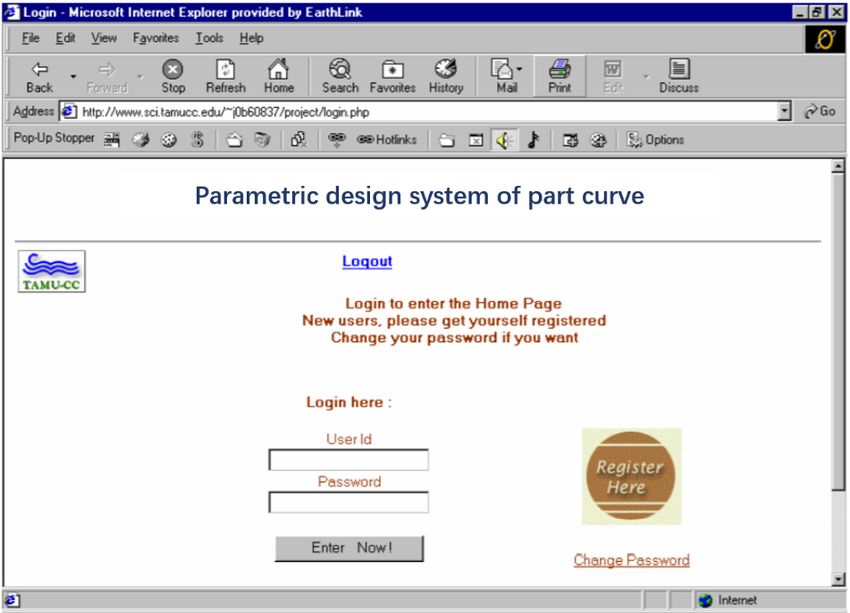
4                               Qin et al. Applied Mathematics and Nonlinear Sciences (aop) 1–11

flexibility for geometric calculations and make it an additional modelling parameter.

3.2   Non-uniform rational B-splines surface

    Similar to the non-uniform rational B-splines curve, a non-uniform rational B-splines surface of degree k × 1
can be expressed as

                                                    m   n
                                                   ∑∑          ωi di Ni,k(u) N j,(un                                         (2)
                                                   i=0 j=(t)

     The control vertex di (i = 0.1, L , m, j = 0, 1, L , n) presents a topological rectangular array and then forms a
control network; ωi is the weighting factor connected with the vertex. We specify the positive weighting factor
ω1,m , ω2,m , ω3,m , ωi,m > 0 at the vertices of the four corners and the remaining ωi ≥ 0, Ni,k(u) (i = 0, 1, L , m) and
Ni,k ( j = 0, 1, L , n) are the canonical B-spline bases of k times in u direction and l times in the v direction, respec-
tively [5]. They are, respectively, determined by the node vector U = [u0 , u1 , . . . , um+k−1 ],V = [v0 , v1 , . . . , vm+l−1 ]
of the u and v directions, according to the De Boer recurrence formula.

4 Parametric design of leg shape

    The aggravated leg shape mentioned in the thesis is a kind of leg shape widely used in Ming and Qing
furniture, and its lower end is like a horse hoof. The middle future hangs upright, and the upper end turns inward
to connect with the teeth. Traditionally, this kind of leg is called a horseshoe leg. The structure and shape of
horseshoe legs are relatively finalised, so we use a parametric design method based on shape feature lines to
construct a mathematical model of the leg shape [6]. The typical size relationship of the two legs (flat legs and
drum legs) is shown in Figure 3 and Table 1. Based on this, we can use a set of parameters to agree on the size
relationship of the horseshoe legs.

                                    Fig. 3 The configuration parameters of the leg shape.

    Most of the parameters for constructing the leg shape are related to the plane curve. Although the curve
segment is on the one-dimensional form of the leg shape rather than on the two-dimensional outline, the relevant
parts of the three-dimensional body are projected from front to back. Still, the curve change directly affects
the construction of the model. Further, from the user’s point of view, when designers in the furniture industry
design leg shapes, after determining the main dimensions of the furniture (length, width, height, leg height etc.),
Art design of industrialised manufacturing furniture products                   5

the primary consideration is also the change of this line. Therefore, based on the above reviews, we use the
mathematical curve as the characteristic line for constructing the leg shape.

                                        Table 1 Furniture leg size relationship.
                                                                      Size relationship
                   Size   Name
                                                                      Flat leg (m) Oblique leg (m)
                   u      Tip width                                   1/15–1/20
                   b      Outer leg width                             0.5–1.0
                   t      The angle of inclination of the foot        0.15–0.65
                   d      Inner crotch width                          0.1–0.8
                   h0     Foot height                                 0.9–1.5        0.9–1.1
                   h1     Inner crotch height                         1.1–1.5        1.1a
                   h2     Tip height                                  2.0–5.0
                   h3     Foot length                                 0.7–1.5        0.23

      The curve non-uniform rational B-splines is expressed as:

                                                             10
                                                             ∑ Vi ωi Ni,3
                                                            i=1
                                                 C(u) =     10
                                                                                                               (3)
                                                            ∑ ωi Ni,3 (u)
                                                           i=1

     Among the 10 model value points on the distinctive line, the points I, II, V and X correspond to the charac-
teristic points A, D, B and C. The two points III and IV are the uniform interpolation points of the DB segment,
and the four points VI, VII, VIII and IX are the consistent interpolation points of the BC segment. After defin-
ing the characteristic line, the cross-sectional shape of the height of a particular point of the leg shape can be
determined, thereby forming the three-dimensional shape of the leg shape [7].

5 Realisation technology of Non-uniform rational B-splines method in leg shape

    Since the CAD platform system involves geometric configuration and is inseparable from the database and
the graphical interface, the database and the graphical interface are substantial software packages. To develop
these low-level frameworks at the same time or on the original basis requires a lot of time and energy from
developers, which is often difficult to adapt to the rapid development of the software industry. At present,
the development of software component technology and object-oriented technology provides an excellent way
to solve the problem, making full use of advanced software platforms, and researching and developing their
superior products at a higher starting point should be a more feasible technical approach.

5.1    Principles of secondary development

    The system is operated under the Windows environment using powerful, object-oriented Visual Basic visual-
programming software. The system uses SolidWorks as the primary platform for its secondary development and
realises the parametric design of the curve of American furniture parts. We use mathematical curves to simulate
part curves to achieve a part curve parametric design system that integrates part curve selection, geometric curve
design, parametric modelling and engineering drawings.
    SolidWorks is a feature-based solid modelling software. The system can give different design schemes to
avoid or reduce errors in the design process. It uses intuitive design technology, Windows OLE technology, Para-
solid kernel and excellent technology integration with third-party software. SolidWorks is currently a commonly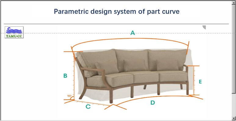
6                           Qin et al. Applied Mathematics and Nonlinear Sciences (aop) 1–11

used 3D CAD software.
     SolidWorks has an open interface, and provides convenient user-development tools and rich data-exchange
methods [8]. The secondary development of SolidWorks is mainly to use its embedded Application Program-
ming Interface (API) objects. Solid Works API provides users with free, open and fully functional development
tools. Reliable Works API provides users with many functions that Visual Basic can call, such as Delphi, VBA
and Visual C++ through OLE technology. These functions are related to the methods and properties of the
object, which improve the programmer’s ability to develop SolidWorks directly. By calling these methods and
setting object properties, users can control various operations on SolidWorks in their applications.

5.2     System overall planning

    According to the characteristics and goals of the system, the system we designed is mainly composed of five
parts: curve-type selection module, geometric curve design module, part 3D modelling module, database query
module and menu plug-in. Simultaneously, we have established a SolidWorks menu plug-in, from which it is
more convenient for users to query and call the required part curves. The overall plan of the system is shown in
Figure 4.

                                             Fig. 4 System master plan.

5.2.1    Curve type selection module
    This module is mainly used for curve selection. After entering the system interface, we select the correspond-
ing mathematical curve type according to user needs and ensure that these are equipped with complementary
graphics and text descriptions [9]. When you click the ‘OK’ button, you will enter the following design interface.
When you click the ‘Cancel’ button, it will return to the program’s main interface.
5.2.2    Geometric curve design module
    This module mainly performs geometric curve drawing. Query the parameters of the required part curve in
the database. After we input the geometric parameters and complete the design calculation, click the ‘Geometric
Curve’ button to draw the geometric curve of the part and save it to the corresponding folder.
5.2.3    Part 3D modelling module
   This module is mainly used for drawing the three-dimensional model of parts and engineering drawings.
Query and enter the corresponding part design parameters in the database. Click the ‘Part Model’ and ‘Export
Engineering Drawing’ buttons to enter the SolidWorks interface of the part 3D model and engineering drawing.
We save the drawn engineering drawings to the corresponding folder.
5.2.4    Database query module
    This module mainly provides users with a convenient platform for querying part curve geometric parameters
and part design parameters [10]. Multiple data tables are used to record different types of part curve data, which
can be continuously expanded, modified and updated. The Access database management system completes this
module.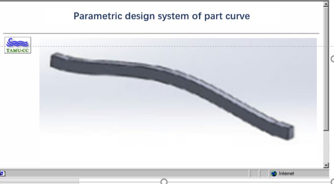
Art design of industrialised manufacturing furniture products                     7

5.2.5    SolidWorks menu plug-in
    The system developed the EXE program of the part curve and developed the SolidWorks menu plug-in (DLL
program) for the user’s convenience. The DLL program hangs different part curves on the main menu of the
SolidWorks software, making the two systems integrated and more flexible and convenient. The procedure flow
of the whole system is shown in Figure 5.

                                               Fig. 5 System flow chart.

5.3     Model construction and modification

    We can use the parametric design method to build the model for the furniture curve and surface modelling
with relatively finalised structural shapes. Through parametric drawing design, we can quickly realise the design
of serialised products or make partial changes to the design works, avoiding designers’ tedious and repetitive
work [11]. The flow chart of furniture leg parameter modelling is shown in Figure 6. The paper adopts the
parametric design method based on the characteristic shape line to construct the leg type mathematical model.
Since the development of the system adopts a modular programming method, it has an excellent interface to
facilitate subsequent development.
    After constructing the initial model, we can quickly and efficiently modify the model according to our re-
quirements. The system uses two commonly used non-uniform rational B-splines curve and surface modification
methods: changing the control vertices and modifying the weight factors of the control vertices. Since we mod-
ify the control vertex coordinates to make the range of the non-uniform rational B-splines curve and surface
repair more significant, we are able to use it for rough repair of the non-uniform rational B-splines curve and
surface. Modifying the weight factor of the control vertex makes the modification range of the non-uniform
rational B-splines curve and surface limited to the convex hull of the control vertex, so it is used to realise the
refinement of the non-uniform rational B-splines curve and surface. The actual matching of control vertices
and weight factors makes the user’s control of curves and surfaces more flexible and the modelling function is
enhanced.
8                           Qin et al. Applied Mathematics and Nonlinear Sciences (aop) 1–11

                               Fig. 6 The flow chart of leg shape parameter modelling.

5.4     Application examples

   We use the example of a cosine curve to simulate the angle of furniture parts to illustrate the operation
method of the whole system, the operation process and the programming code to realise the process.
5.4.1    System start-up interface
    In the Windows environment, we open the executable program of this system and start the login interface of
the furniture part curve parametric design system. We enter the corresponding account and password to enter
the following window interface, as shown in Figure 7.

                                                 Fig. 7 Login screen.

5.4.2    Curve-type selection interface
    After we enter the login interface, an interface window–shown in Figure 8–will pop up, and we can use it
to select the desired curve type. Select the cosine curve here, and then click the button to the right to pop up
a legend and text description of the cosine curve. If you are sure of the choice made, click the ‘OK’ button to
enter the design interface of the geometric cosine curve.
Art design of industrialised manufacturing furniture products 9
Fig. 8 Curve-type selection interface.
5.4.3 Geometric curve design interface
After viewing the cosine curve data table, enter the name of the required curve part, and we obtain the geo-
metric parameters and enter them in the corresponding positions. The relevant parameters cover four parameters:
amplitude, period, left interval and suitable interval. We can calculate the value of through four parameters [12].
In this way, a geometric curve model can be built in SolidWorks and saved to the corresponding folder. After
completion, click the ‘Enter Part 3D Modelling Interface’ button to enter the following interface, as shown in
Figure 9 [13].
Fig. 9 Geometric curve design interface and model.10 Qin et al. Applied Mathematics and Nonlinear Sciences (aop) 1–11
5.4.4 Part 3D modelling interface
The primary purpose of the three-dimensional modelling design is to generate the three-dimensional model
of the part and the creation of the engineering drawing interface, as shown in Figure 10.
Fig. 10 3D modelling design of curved parts.
After ascertaining the corresponding part design parameters from the data table, we input them into the
corresponding position. There are three parameters of straight-line length, part width and stretched thickness
[14]. After inputting the parameters, click ‘Part Model’ to build the necessary curve part in SolidWorks, as
shown in Figure 11.
Fig. 11 3D model of the curved part.
According to the actual needs, we can click the ‘engineering drawing’ button to generate the corresponding
engineering drawing, as shown in Figure 12.
6 Conclusion
The paper analyses the modelling characteristics of the furniture leg curve and the method of mathematical
curve simulating the leg curve. We use SolidWorks API technology and VB development tools to realise the
parametric design of the furniture leg curve. The paper expounds on the principles of system development,
parametric modelling methods and overall system planning and uses cosine curve to simulate furniture leg curve
as an example to analyse the operation process of the system and the use of the SolidWorks menu plug-in. The
design method is simple to operate. The designer can perform curve design and automatic modelling through
simple human–computer interaction, which significantly improves the design efficiency, shortens the productArt design of industrialised manufacturing furniture products 11
Fig. 12 Engineering drawing of a curved part.
development cycle and enables the designer to spend more time and energy in product innovation design.
References
[1] Dobrzański, L. A., & Dobrzańska-Danikiewicz, A. D. Why are carbon-based materials important in civilisation
progress and especially in the industry 4.0 stage of the industrial revolution. Materials Performance and Character-
ization., 2019. 8(3): 337-370.
[2] Hasan, K. F., Horváth, P. G., Bak, M., & Alpár, T. A state-of-the-art review on coir fiber-reinforced biocomposites.
RSC Advances.,2021. 11(18): 10548-10571.
[3] Demarco, F., Bertacchini, F., Scuro, C., Bilotta, E., & Pantano, P. The development and application of an optimization
tool in industrial design. International Journal on Interactive Design and Manufacturing (IJIDeM).,2020. 14(3): 955-
970.
[4] Şahin, R. & Yağcı, O. A new generalization of pochhammer symbol and its applications. Applied Mathematics and
Nonlinear Sciences., 2020.5(1): pp. 255-266.
[5] Modanli, M. & Akgül, A. On Solutions of Fractional order Telegraph partial differential equation by Crank-Nicholson
finite difference method. Applied Mathematics and Nonlinear Sciences., 2020.5(1): pp. 163-170.
[6] Lyu, G., & Brennan, R. W. Towards IEC 61499-Based Distributed Intelligent Automation: A Literature Review. IEEE
Transactions on Industrial Informatics.,2020. 17(4): 2295-2306.
[7] Portioli-Staudacher, A., Costa, F., & Thürer, M. The use of labour flexibility for output control in workload controlled
flow shops: A simulation analysis. International Journal of Industrial Engineering Computations.,2020. 11(3): 429-442.
[8] Galizia, F. G., ElMaraghy, H., Bortolini, M., & Mora, C. Product platforms design, selection and customisation in
high-variety manufacturing. International Journal of Production Research.,2020. 58(3): 893-911.
[9] Muminovic, A. J., Saric, I., Mesic, E., Pervan, N., & Delic, M. Research about characteristics of designs from industrial
designers and product designers. Periodicals of Engineering and Natural Sciences.,2019. 7(2): 860-869.
[10] Okwu, M. O., & Nwachukwu, A. N. A review of fuzzy logic applications in petroleum exploration, production and
distribution operations. Journal of Petroleum Exploration and Production Technology.,2019. 9(2): 1555-1568.
[11] Tamayo, E. C., Khan, Y. I., Qureshi, A. J., & Al-Hussein, M. Conceptual design of an automated steel wall framing
assembly using axiomatic design and integrated function model. Construction Robotics.,2019. 3(1): 83-101.
[12] Zhang, L., & Ma, L. The relationship between industrial structure and carbon intensity at different stages of eco-
nomic development: an analysis based on a dynamic threshold panel model. Environmental Science and Pollution
Research.,2020. 27(26): 33321-33338.
[13] Blomqvist, L., Berg, S., & Sandberg, D. Distortion in laminated veneer products exposed to relative-humidity
variations-Experimental studies and finite-element modelling. BioResources., 2019.14(2): 3768-3779.
[14] Panetta, J., Konaković-Luković, M. I. N. A., Isvoranu, F., Bouleau, E., & Pauly, M. X-shells: A new class of deployable
beam structures. ACM Transactions on Graphics (TOG).,2019. 38(4): 1-15.You can also read