SERIES 100 UL ROOF MOUNT SYSTEM - SnapNrack Solar Mounting Solutions Code Compliant Installation Manual
←
→
Page content transcription
If your browser does not render page correctly, please read the page content below
PV Mounting System
                                     2703

SERIES 100 UL
ROOF MOUNT SYSTEM
SnapNrack Solar Mounting Solutions
Code Compliant Installation Manual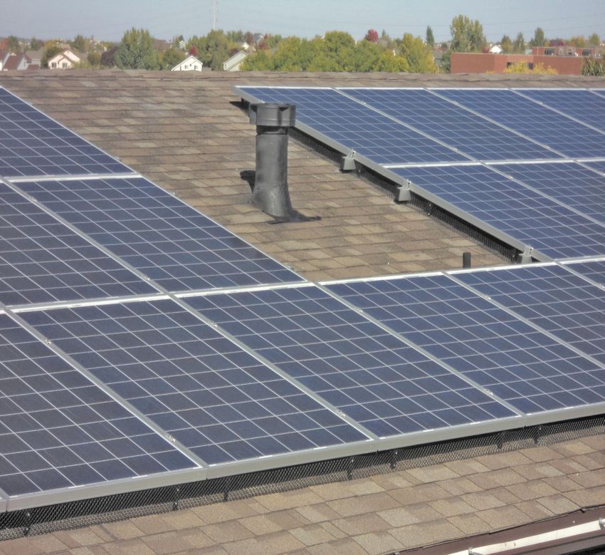
Series 100 UL                         Series 100 UL Introduction

                Intro/Configuration
                                      SnapNrack Series 100 UL PV Mounting System offers a low profile,
                                      visually appealing, photovoltaic (PV) module installation system. This innovative
                                      system simplifies the process of installing solar PV modules, shortens installation
                                      times, and lowers installation costs.
                                      SnapNrack systems, when installed in accordance with this manual, will be
                                      structurally adequate for the specific installation site and will meet the local
                                      and International Building Code. Systems will also be bonded to ground, under
                                      SnapNrack's UL 2703 Certification.
                                      The SnapNrack installation system is a set of engineered components that can
                                      be assembled into a wide variety of PV mounting structures. It is designed to be
                                      installed by qualified solar installation technicians. With SnapNrack you will be
                                      able to solve virtually any PV module mounting challenge.
                                      Table of Contents

                                      Step 1: Project Plans
                                        Configuration ����������������������������������������������������������������������������������������������3
                                        Surveying and Layout��������������������������������������������������������������������������������� 4
                                      Step 2: Roof Attachment
                                        Flashed L-Foot- For Compoistion Shingle����������������������������������������������� 6
                                        Standoff Post- For All Roofing Types������������������������������������������������������� 8
                                        Standoff Options �������������������������������������������������������������������������������������� 10
                                        Universal Tile Roof Hook �������������������������������������������������������������������������� 12
                                        Flat Tile Roof Hook������������������������������������������������������������������������������������ 14
   Step 1: Project Plans

                                        Hanger Bolt- For All Roofing Types �������������������������������������������������������� 16
                                        Metal Roof Base ���������������������������������������������������������������������������������������� 18
                                        Corrugated Roof Block- For Corrugated Metal ������������������������������������� 20
                                        Tilt Mount 5°-15°����������������������������������������������������������������������������������������22
                                        Tilt Mount 10°-45°������������������������������������������������������������������������������������ 24
                                        Seam Clamp- For Standing Metal Seam������������������������������������������������� 26
                                      Step 3: Leveling Rails
                                        installing and Leveling Rails ������������������������������������������������������������������� 28
                                      Step 4: Attaching Modules
                                        Attaching Modules����������������������������������������������������������������������������������� 30
                                      Step 5: Select Any Racking Accessories
                                        Edge Screen ����������������������������������������������������������������������������������������������32
                                        Wire Management������������������������������������������������������������������������������������� 34
                                        Micro inverter Attachment����������������������������������������������������������������������� 36
                                        Rail Cutting Tool and End Cap ��������������������������������������������������������������� 40
                                      System Ground
                                        System Ground����������������������������������������������������������������������������������������� 38
                                      High Tilt Tool
                                        High Tilt Tool��������������������������������������������������������������������������������������������� 42

                                      Appendix ����������������������������������������������������������������������������������������������������� 44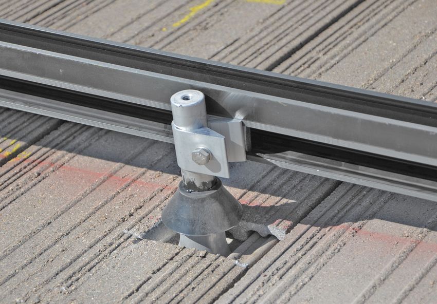
How to Configure Your System                                                     Series 100 UL
First calculate the spans and penetration count. There is                        Roof Mounted System
a SnapNrack span calculation table on the back of this
Manual. Determine site conditions: general building height,
                                                                                  Safety Guidance
array pitch, the wind speed, and snow load or topographical                       - Always wear the proper OSHA approved
condition. Find appropriate railspan from table.                                  safety equipment when working on a roof .
Span Table Example                                                                - Safety equipment should be checked
                                                                                  annually for wear and quality.
 Building Height                               0 - 30 ft
 Array Pitch                                   16°                                - Always wear proper eye protection.
 2012 IBC Wind Speed                           120 mph                            - When walking on the roof avoid walking
 Snow Load                                     8 lbs/ft²                          on installed rails. If this is unavoidable check
                                                                                  L-feet for fatigue before final installation.
 Topo. Cond.                                   None
 Rail Span                                     104"                               - Appropriate fall protection gear should
                                                                                  be used. Extreme caution should be
 Rail Span on 24" spacing roof                 96" (8 ft)                         used when near the edge of the roof.
 Do edge/corner reductions apply               Yes, shaded cell
 Edge Zone Span                                72" (6 ft)
 Corner Zone Span                              24" (2 ft)

*CS-Consult                                                 MODULE OVERHANG       Notes
                                                            (NOT TO EXCEED 25%    - The UL Listing covers bonding for a load rating up to 45 psf.
 Structural Engineer                                        OF MODULE LENGTH)
                                                                                  - Series 100 UL has been tested with the following
                                                                                  UL Listed modules: See Appendix on page 40.

                                                                                  - These systems have been evaluated for module to system
                                                                                  bonding, only to the requirements of UL Subject 2703.

                                                                                  - This system has also been evaluated for a Class A System Fire
                   RAIL SPAN                                                      Classification for a steep-sloped roof with Type 1 modules.

                              RAIL END OVERHANG
                          (NOT TO EXCEED 34% OF
                           ACCEPTABLE RAIL SPAN)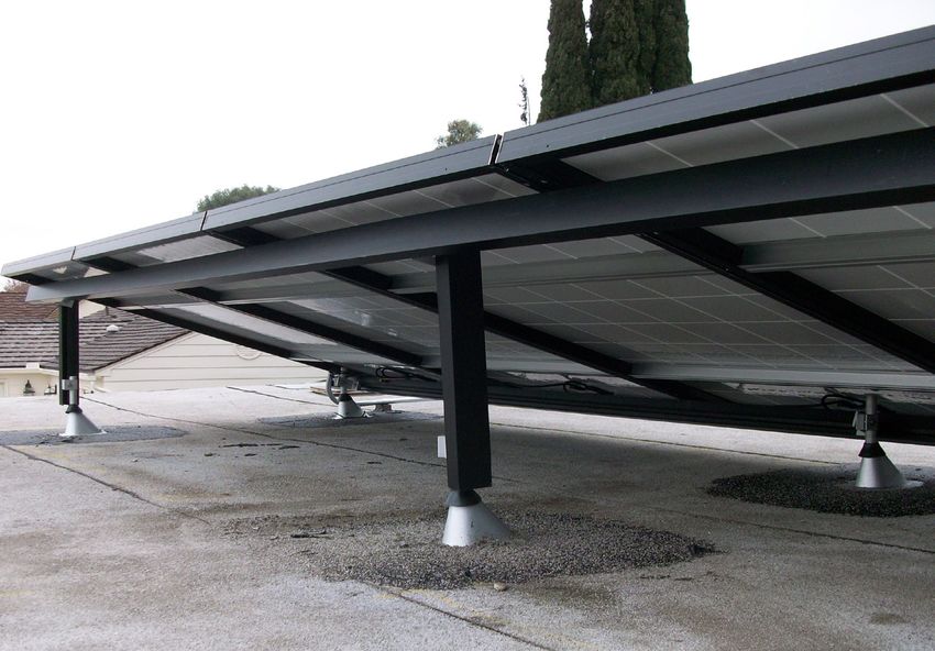
Series 100 UL
Surveying and Layout
Survey the Site
Measure the roof surfaces and develop an accurate drawing, including
any obstacles such as chimneys and roof vents.
If plans are available, check to make sure that the plans match the final
structure.
Review the shading pattern across the roof surface from the residence itself,
from adjacent structures, and from other nearby features such as trees.
Identify any roof access areas or keep-out areas as required by the local
jurisdiction.
Confirm roof construction, type, and condition.
Assess roof rafter size, material, and spacing to confirm that the structure is
sound and can support the additional load of the array.
Identify any construction anomalies that may complicate the process of
locating rafters from the roof surface.
If you find structural problems such as termite damage or cracked rafters
that may compromise the structure’s integrity, consult a structural engineer.
MODULE WIDTH
MODULE LENGTH
PORTRAIT MODE LANDSCAPE MODE
Develop a Layout
Using the information collected in the site survey and from the span tables, complete a
system layout showing array location and distances from key roof features. Include
any information necessary for the permitting process.
Typically, PV modules are installed in portrait mode, with the long side of the
module running up the roof slope and the rails running horizontally across the roof
perpendicular to the roof rafters, which commonly run down slope.
4
Series 100 UL
Arrays can also be installed in landscape mode, with the         Surveying and Layout
modules oriented so that their long edge runs horizontally
across the roof and the rails run up the roof slope. Landscape
mode is typically used in cases where the roof has been          Tips and Tricks
constructed with structural elements running horizontally        - Layout the entire array on the roof by
                                                                 drawing all of the corners of the modules
across the roof, but can also be used on standard residential    on the roof with a roof marking crayon.
buildings for a variety of reasons including to facilitate a
convenient layout. When laying out the array, be sure to leave   - Use a chalk line to help identify
space for the module clamps on the rails. Module mid clamps      the rest of the roof penetrations
are installed between modules in a row and require 0.5 inch
                                                                 - When leveling rails, hand tighten the
of space between the modules.                                    hardware to easily level and position
                                                                 the rails. Once rails are level, fully
Adjustable end clamps require 1.5 inches of extra rail to        tighten hardware to specified torque.
extend past the end of the module frame. If using the
Universal End Clamp, the rail is first cut flush to the module
using the rail cutting tool.

When installing multiple rows of modules, a minimum
spacing gap of 1/8" should be used between rows.

Submit array plans to local permitting jurisdiction and
proceed with the roof layout only when all permits for
the project have been granted by the authority having
jurisdiction.

Transfer the array layout to the roof using a roof marking
crayon to mark the inside and outside corners of the array.
Locate the estimated rafter positions and mark them in the
array area with a roof marking crayon.

Transfer rail and estimated attachment locations to the roof,
noting that attachments will be located at intersections of
rails and rafters. Layout rails such that module frame ends
do not overhang mounting rails by more than 25% of total
module length.

Project Information Sections

       Building Height
            Roof Pitch
          Wind Speed
           Snow Load
           Topo. Cond.              Max Rail Span

    Roof Structure Type
      Roff Structure Size                                        Notes
                                                                 - SnapNrack engineered systems should
    Roof Structure Span
                                                                 only be used with SnapNrack components
                                                                 and hardware. Any alternate application
  Roof Type & Condition                                          may void the warranty and structural
                                                                 calculations could become invalid.
 Stories from the Ground
        Roof Orientation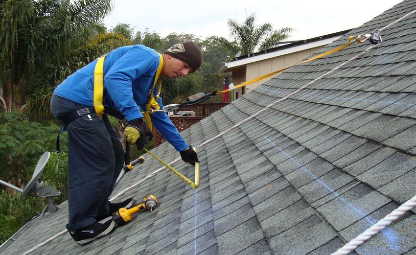
Series 100 UL
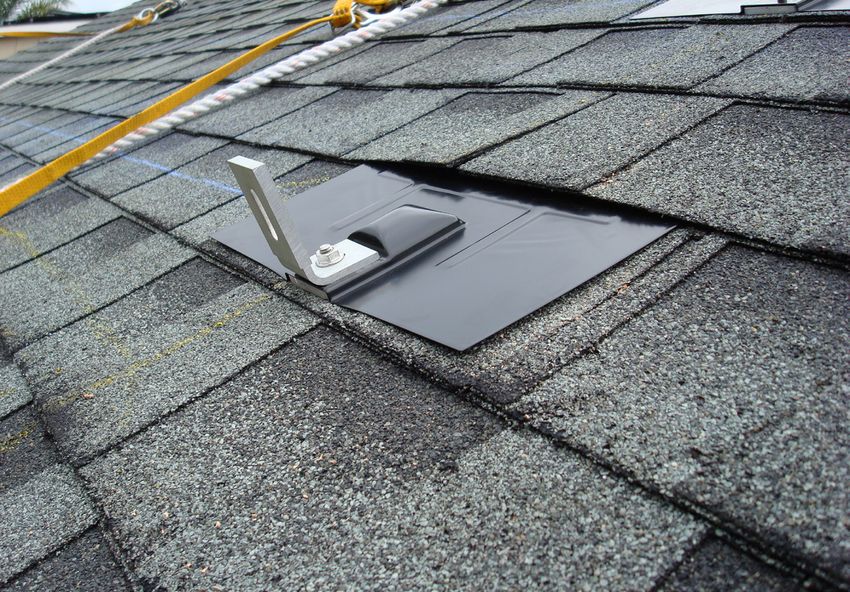
Flashed L-Foot
Required Tools:
Hammer Or Stud Finder
Roof Marking Crayon Dimensioned
Drill with 1/8 inch Pilot Drill Bit
Roof Sealant L-Foot
Torque Driver with Bit Adapter
1/2 inch Socket Wrench 1-1/2"
Materials Included in Series 100 L-Foot Kit:
(1) SnapNrack Flashed Base
(1) SnapNrack Composition Flashing
(1) SnapNrack L Foot, Composition 92°
(1) 5/16in- 18 SS Flange Hex Nut 3" 92°
(1) 5/16in Flange Bolt
(1) SnapNrack Bonding Channel Nut, 5/16in - 18
Other Materials Required:
1-3/4"
(1) 5/16 in Lag Screw
(1) 5/16 in Washer
When To Use:
Composite Shingle Roofs
Step 2: Roof Attachment
Technical L-Foot Data:
Material 6000 Series Heat Treated Aluminum
Finish Class 2 Anodized Finish
Clear and Black Finish Available
Weight 0.16 LBS
Design Uplift Load 200 LBS Uplift
Design Ultimate Load 1000 LBS Uplift
Dimensioned Assembly
1"
2
31 "
2
1"
4"
12"
6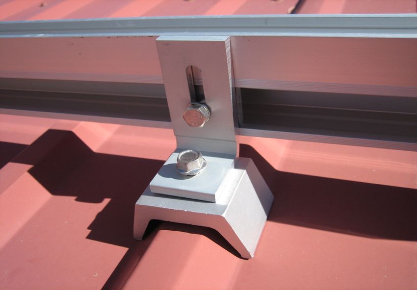
Series 100 UL
1) Locate the rafter   2) Drill the pilot hole
                                                 Flashed L-Foot

                                                 Step-by-Step Instructions
                                                 1) Locate the rafter underneath
                                                 the decking of the roof by looking
                                                 underneath the eaves or in the attic.

                                                 2) Drill a pilot hole through the
                                                 roofing material into the rafter to
                                                 ensure that the lag bolt will be located
                                                 into a solid portion of the rafter. If the
                                                 rafter is not found then seal the pilot
                                                 hole immediately with roofing sealant.

                                                 3) Apply roofing sealant to
                                                 the bottom of the base and
3) Prep the base       4) Attach base            directly onto the lag bolt to
                                                 ensure a water tight seal.

                                                 4) Attach the L-foot base with
                                                 a 5/16” lag bolt and a minimum
                                                 embedment of 2 ½” lag shank
                                                 into the rafter. Tighten Lag bolt
                                                 to seat with a hand wrench.

                                                 5) Slide the flashing underneath
                                                 the row of shingles, directly
                                                 above the installed standard base,
                                                 and then line up the hole in the
                                                 flashing with the threads on the
                                                 base. It may be necessary to pry
                                                 up shingles with a breaker bar.
5) Set the flashing    6) Attach L-Foot
                                                 6) Attach the L-foot to the threaded
                                                 portion of the base that is protruding
                                                 from the flashing. Then tighten
                                                 the flange bolt over the threads
                                                 to 10 – 16 ft-lbs. The L-foot can
                                                 be attached in any orientation.

                                                 Notes
                                                 - Alternative 90° L Foot included
                                                 in UL 2703 Listing
                                                 - SnapNrack engineered systems should
                                                 only be used with SnapNrack components
                                                 and hardware. Any alternate application
                                                 may void the warranty and structural
                                                 calculations could become invalid.

                                                 Warning
                                                 - If a pilot hole is drilled and a rafter is not
                                                 found, immediately seal pilot hole with
                                                 roofing sealant to avoid water damage.
                                                 - Do not over tighten hardware.
                                                 - Always wear fall protection
                                                 and safety gear.

                                                 Design Tools
                                                 - SnapNrack has a suite of design tools
                                                 to help configure your PV installation to
                                                 be an accurate and fast install. Please
                                                 visit us at: www.SnapNrack.com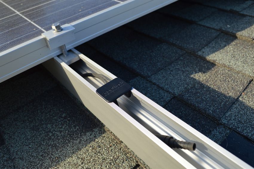
Required Tools:
Series 100 UL
Standoff Post
When To Use:
Hammer or Stud Finder Concrete or Clay Tile Roofs
Roof Marking Crayon
Drill with 1/8 inch Pilot Drill Bit
Roof Sealant
Torque Driver with Bit Adapter
Channel Locks
1/2 inch Socket Wrench
Materials Included In Series 100 Standoff Kit:
(1) SnapNrack Standoff Base
(1) SnapNrack Standoff Shaft
(1) SnapNrack Rubber Rain Collar
(1) SnapNrack Standoff Clamp
(1) 5/16in SS Split Lock Washer
(1) 5/16in - 18 X 2in SS HCS Bolt
(1) SnapNrack Bonding Channel Nut, 5/16in - 18
Other Materials Required:
(1) 5/16in Lag Screw
(1) 5/16in Washer
(1) Roof Cone Flashing
Technical Standoff Shaft Data:
Material 6000 Series Heat
Treated Aluminum All Standoff shafts
Finish Mill are mill finished
Weight 5.5” Shaft = 0.4 LBS
7” Shaft = 0.5 LBS
8.5” Shaft = 0.6 LBS
Design Uplift Load 200 LBS Uplift
Design Ultimate Load 1600 LBS Uplift
Dimensioned Assembly Dimensioned Shaft
1-1/2"
1"
5/16"-18
1-1/2"
1"
10"
7-1/2"
8-1/2"
7"
5-1/2"
1/2"
3-1/2"
8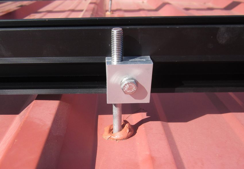
Series 100 UL
1) Remove tile and     2) Drill pilot hole        Standoff Post
   locate the rafter
                                                  Step-by-Step Instructions
                                                  1) Remove roof tile where the
                                                  penetration will be installed. Locate
                                                  the rafter underneath the decking
                                                  of the roof by locating under the
                                                  eave, in the attic, or by tapping
                                                  the roof surface with a hammer.

                                                  2) Drill a pilot hole through the roofing
                                                  material into the rafter to ensure that
                                                  the lag bolt will be located into a solid
                                                  portion of the rafter. If the rafter is
                                                  not found then seal the pilot hole
                                                  immediately with roofing sealant.
3) Prep the base and   4) Set flashing
  attach base                                     3) Apply roofing sealant to the bottom
                                                  of the base and directly onto the
                                                  lag bolt to ensure a water tight seal.
                                                  Attach the Standoff base with a 5/16”
                                                  lag bolt and a minimum embedment of
                                                  2 ½” lag shank into the rafter. Tighten
                                                  lag bolt to seat using a hand wrench.

                                                  4) Set the flashing by sliding the
                                                  flashing underneath the row of tiles
                                                  directly above the installed base, with
                                                  the hole in the flashing directly above
                                                  the threaded portion of the base.

                                                  5) Attach the standoff shaft by
5) Attach post         6) Replace tile and        sliding it through the hole in the
                          attach standoff clamp   flashing and tightening it onto
                                                  the threads protruding from the
                                                  base snug with channel locks.

                                                  6) Cut the tile to fit around the
                                                  flashing, replace the tile, then attach
                                                  the standoff clamp by first sliding the
                                                  rubber rain collar over the standoff
                                                  shaft then the standoff clamp with
                                                  bolt, washer and channel nut.

                                                  Notes
                                                  - SnapNrack engineered systems should
                                                  only be used with SnapNrack components
                                                  and hardware. Any alternate application
                                                  may void the warranty and structural
                                                  calculations could become invalid.
                                                  Warning
                                                  - If a pilot hole is drilled and a rafter is not
                                                  found, immediately seal pilot hole with
                                                  roofing sealant to avoid water damage.
                                                  - Do not over tighten hardware.
                                                  - Always wear fall protection
                                                  and safety gear.

                                                  Design Tools
                                                  - SnapNrack has a suite of design tools
                                                  to help configure your PV installation to
                                                  be an accurate and fast install. Please
                                                  visit us at: www.SnapNrack.com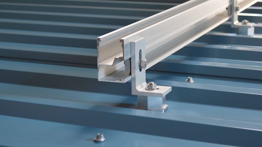
Series 100 UL
Standoff Options
Materials Included In Series 100 Standoff Kit Standard Standoff Base
(Steel Structural Member):
(1) SnapNrack Standoff Base
(1) SnapNrack Standoff Shaft
(1) SnapNrack Rubber Rain Collar
(1) SnapNrack Standoff Clamp
(1) 5/16in SS Split Lock Washer
(1) 5/16in - 18 X 2in SS HCS Bolt
(1) SnapNrack Bonding Channel Nut, 5/16in - 18
Other Materials Required:
(1) 1/4in Tek Screw
(1) Roof Cone Flashing When To Use:
Steel Structural
Member Configurations
Materials Included In Series 100 Four Hole Base
Four Hole Standoff Kit:
(1) SnapNrack Four Hole Standoff Base
(1) SnapNrack Standoff Shaft
(1) SnapNrack Rubber Rain Collar
(1) SnapNrack Standoff Clamp
(1) 5/16in SS Split Lock Washer
(1) 5/16in - 18 X 2in SS HCS Bolt
(1) SnapNrack Bonding Channel Nut, 5/16in - 18
Other Materials Required:
(4) Wood Screws 1/4"
(1) Roof Cone Flashing
When To Use:
TJI Jolsts
10Materials Included In Series HD Base Series 100 UL
100 Heavy Duty Standoff Kit: Standoff Options
(1) SnapNrack HD Standoff Base Step-by-Step Instructions For
(1) SnapNrack HD Standoff Shaft
(1) SnapNrack Rubber Rain Collar Zee Purlin Installation
(1) SnapNrack Standoff Clamp 1) Follow the instruction exactly
(1) 5/16in SS Split Lock Washer as the SnapNrack Standoff
(1) 5/16in - 18 X 2in SS HCS Bolt penetration. Substituting the tek
(1) SnapNrack Bonding Channel Nut, Screw for the 5/16” lag bolt.
5/16in - 18
Other Materials Required: Step-by-Step Instructions For
(2) 5/16in Lag Screw Four Hole Installation
(1) Roof Cone Flashing 1) Follow the instruction exactly as the
SnapNrack regular Standoff penetration.
Substituting the base for the four hole base
When To Use: and 1/4" wood screws for the 5/16” lag bolt.
Foam Roofs Step-by-Step Instructions For
Heavy Duty Installation
1) Remove the foam roofing above
the rafter to be installed on.
2) Attach the SnapNrack heavy duty
standoff base directly to the exposed
rafter using (2) 5/16” lag bolts.
3) Screw in the SnapNrack HD Standoff
to the base snug with channel locks.
4) Replace the foam roofing
that was removed.
5) Flash the standoff by sliding the cone
flashing over the exposed standoff and
heat weld the rubber membrane around
the flashing for a water tight seat.
6) Attach remaining hardware as in
the standard SnapNrack standoff.
Notes
- SnapNrack engineered systems should
only be used with SnapNrack components
and hardware. Any alternate application
may void the warranty and structural
calculations could become invalid.
Warning
- If a pilot hole is drilled and a rafter is not
found, immediately seal pilot hole with
roofing sealant to avoid water damage.
- Do not over tighten hardware.
- Always wear fall protection
and safety gear.
Design Tools
- SnapNrack has a suite of design tools
to help configure your PV installation to
be an accurate and fast install. Please
visit us at: www.SnapNrack.comSeries 100 UL
Tile Roof Options
Required Tools:
Hammer or Stud Finder
Roof Marking Crayon When To Use:
Drill with 1/8 inch Pilot Drill Bit Flat, Wave and S Style
Roof Sealant Concrete Tile Roofs
Torque Driver with Bit Adapter
1/2 inch Socket Wrench
Flat Pry Bar
Materials Included In Universal Tile Roof Hook:
(1) SnapNrack Universal Tile Roof Hook Base
(1) SnapNrack Universal Tile Roof Hook Arm
(2) 5/16in Flange Bolt
(2) SnapNrack Bonding Channel Nut, 5/16in - 18
Other Materials Required:
(2) 5/16in Lag Screw
(2) 5/16 Washer
Roof Felt of Flexible Flashing (when
required for deck-level flashing)
Technical Universal Tile Roof Hook Data:
Material 6000 Series Heat Treated Aluminum Base
304 Stainless Steel Arm
Finish Mill Finish Base
Bare Metal Arm
Weight 2 lbs
Design Uplift Load 175 lbs
Design Ultimate Load 650 lbs
Dimensioned Assembly:
8.8
0
7.2
5
8.0
0
12Series 100 UL
1) Locate the rafter 2) Drill pilot holes Universal Tile Roof Hook
Step-by-Step Instructions
1) Use pry bar to remove roof tile
where the base will be installed.
Locate the rafter underneath the
decking of the roof by locating under
the eave, in the attic, or by tapping
the roof surface with a hammer.
2) Align the base over the rafter so
the hook can enter at the valley of
a tile and not extend beyond the
edge of the base. Drill two pilot
holes in the center of the rafter. If
the rafter is not found then seal the
3) Install Tile Hook base 4) Position Tile Hook arm pilot hole immediately with sealant.
3) Apply roofing sealant to the bottom
of the base and directly onto each
lag screw. Attach the base with two
5/16” lag screws with washers at a
minimum 2 ½” lag shank embedment
into the rafter. Tighten the lag screw
to seat using a hand wrench.
4) Insert the top end of the arm into
the groove at the top of the base. The
arm will move freely in the base until
the channel nut is tightened. Position
the arm over the valley of the tile
below, then lower the arm down.
5) Work channel nut into 6) Attach Tile Hook arm
groove to base 5) As you lower the arm you can
work the channel nut into the
lower groove of the base without
removing the channel nut.
6) Ensure the hook is aligned with
the valley of the tile. Tighten the bolt
in the channel nut and be sure the
arm fully seats to the base. The arm
will work in any position on the base
independent of the lag screw location.
7) If deck-level flashing is required,
integrate roof felt or a flexible flashing
with the existing underlayment
7) Optional deck-level 8) Replace tile and install and over the Tile Hook.
flashing rail
8) Replace the roof tiles and
install SnapNrack Standard Rail
directly to the available channel
nut on the Tile Hook arm.
Notes
- SnapNrack engineered systems
should only be installed with SnapNrack
components and hardware. Any alternate
application may void the warranty,
the UL 2703 Listing, and the structural
calculations may no longer be valid.Series 100 UL
Tile Roof Options
Required Tools:
Hammer or Stud Finder When To Use:
Roof Marking Crayon Flat Concrete
Drill with 1/8 inch Pilot Drill Bit Tile Roofs
Roof Sealant
Torque Driver with Bit Adapter
1/2 inch Socket Wrench
Flat Pry Bar
Materials Included In Flat Tile Roof Hook:
(1) SnapNrack Flat Tile Hook
(1) 5/16in Flange Bolt
(1) SnapNrack Bonding Channel Nut, 5/16in - 18
Other Materials Required:
(2) 5/16in Lag Screw
(2) 5/16 Washer
Roof Felt of Flexible Flashing (when
required for deck-level flashing)
Technical Flat Tile Roof Hook Data:
Material 304 Stainless Steel
Finish Bare Metal
Weight 1.2 lbs
Design Uplift Load 175 lbs
Design Ultimate Load 650 lbs
Dimensioned Flat Tile Roof Hook:
8.7
8
6.1
9
1.
25
14Series 100 UL
1) Locate the rafter 2) Drill pilot holes Flat Tile Roof Hook
Step-by-Step Instructions
1) Use pry bar to remove roof tile
where the Tile Hook will be installed.
Locate the rafter underneath the
decking of the roof by locating under
the eave, in the attic, or by tapping
the roof surface with a hammer.
2) Align the Tile Hook over the
rafter and drill two pilot holes in
the center of the rafter. If the rafter
is not found then seal the pilot
hole immediately with sealant.
3) Install Tile Hook 4) Optional deck-level
3) Apply roofing sealant to the bottom
flashing of the Tile Hook and directly onto each
lag screw. Attach the base with two
5/16” lag screws with washers with a
minimum 2 ½” lag shank embedment
into the rafter. Tighten the lag screw
to seat using a hand wrench.
4) If deck-level flashing is required,
install a flexible flashing over the Tile
Hook. See Flat Tile Roof Hook – Deck-
Level Flashing section for more details..
5) Replace the roof tiles and
install SnapNrack Standard Rail
directly to the available channel
5) Replace tile and install nut on the Tile Hook arm.
rail
Notes
- SnapNrack engineered systems
should only be installed with SnapNrack
components and hardware. Any alternate
application may void the warranty,
the UL 2703 Listing, and the structural
calculations may no longer be valid.
Warning
- If a pilot hole is drilled and a rafter is not
found, immediately seal pilot hole with
roofing sealant to avoid water damage.
- Do not over tighten hardware.
- Always wear fall protection
and safety gear.
Design Tools
- SnapNrack has a suite of design tools
to help configure your PV system to be
an accurate and fast installation. Please
visit us at: www.SnapNrack.comSeries 100 UL
1) Prepare underlayment 2) Peel off backing Flat Tile Roof Hook
Optional Deck-Level Flashing
Step-by-Step Instructions
1) Prepare the underlayment surface
for adhesion. The surface should be
dry, clean and free of any dirt, dust
or foreign matter that may prevent
adhesion. Clean the surface around the
Tile Hook with a brush of medium-stiff
bristles. If necessary, prime the surface
with compatible spray or paint primer.
2) Peel off the backing from a
9-in. square of flexible flashing.
3) Apply flashing 4) Roll flashing
3) Apply flexible flashing centered
laterally over tile hook and abutted
to the tile hook arm. Ensure tape
adheres to the corners between
the edges of the Tile Hook and the
underlayment as well as over the lag
screw heads and tile hook surface.
4) Press and smooth out any creases
or air bubbles with a roller to maximize
contact of the flashing adhesive to
100% of the surface and Tile Hook.
5) Peel off the backing from a 4-in.
5) Peel off backing 6) Roll strip by 13-in. strip of flexible flashing.
6) Apply the strip with 2-in. laps at
the top and side edges of the square
flashing. Roll out any creases or air
bubbles between the strip, the flashing
and the underlayment surface.
Notes
- SnapNrack recommends testing
underlayment surfaces for adhesion. If
adhesion is found to be marginal, then
a primer is recommended to ensure
optimal adhesion. Refer to flexible
flashing manufacturer’s technical
data for primer recommendations.
- SnapNrack recommends using
Protecto Wrap Protecto Seal
45 waterproofing membrane,
or equivalent, as the flexible
flashing and lap material.Series 100 UL
Hanger Bolt
Required Tools:
Hammer or Stud Finder
Roof Marking Crayon
Drill with 1/8 inch Pilot Drill Bit
Roof Sealant
Threaded Bit Adapter
1/2 inch Socket Wrench
Torque Wrench
Materials Included In Series 100 Hanger Bolt Kit:
(1) SnapNrack Hanger Bolt Clamp Front
(1) SnapNrack Hanger Bolt Clamp Back
(1) 5/16in SS Split Lock Washer
(1) 5/16in - 18 X 1in SS HCS Bolt
(1) SnapNrack Bonding Channel Nut,
5/16in - 18
Other Materials Required:
(1) 3/8” Stainless Steel Hanger Bolt
Dimensioned Assembly
1-1/2"
3/4"
3/8"
When To Use:
Any Roof Style
Dimensioned Hanger
Bolt Clamp
1"
R 0.188" 3/4"
8" TYP 1-1/2"
R 0.17"
Technical Hanger Bolt Clamp Data:
Material 6000 Series Heat
Treated Aluminum
Color Class 2 Anodized Finish
Clear Finish Available
Weight 0.7 LBS
Design Uplift Load 200 LBS Uplift
Design Ultimate Load 1600 LBS Uplift
17Series 100 UL
1) Locate the rafter 2) Drill the pilot hole Hanger Bolt
Step-by-Step Instructions
1) Locate the rafter underneath
the decking of the roof.
2) Drill a pilot hole through the roofing
material into the rafter to ensure that
the lag bolt will be located into a
solid portion of the rafter. If the rafter
is not found then seal the pilot hole
immediately with roofing sealant.
3) Apply roofing sealant directly onto
the pilot hole and the hanger bolt
3) Prep the bolt and hole 4) Install hanger bolt lag to ensure a water tight seal.
4) Attach the hanger bolt using the
threaded bit adapter with a minimum
embedment of 2 ½” lag shank into the
rafter. Tighten Lag bolt to seat.
5) Attach the channel nut of the
hanger bolt assembly into rail.
6) Then attach the hanger bolt clamp by
setting it around the threaded portion
of the hanger bolt to the desired height
and tighten silver hardware to 10-16 ft-
lbs and black hardware to 8-10 ft-lbs.
5) Set in rail 6) Attach to hanger bolt
Notes
- SnapNrack engineered systems should
only be used with SnapNrack components
and hardware. Any alternate application
may void the warranty and structural
calculations could become invalid.
Warning
- If a pilot hole is drilled and a rafter is not
found, immediately seal pilot hole with
roofing sealant to avoid water damage.
- Do not over tighten hardware.
- Always wear fall protection
and safety gear.
Design Tools
- SnapNrack has a suite of design tools
to help configure your PV installation to
be an accurate and fast install. Please
visit us at: www.SnapNrack.comSeries 100 UL
Metal Roof Base
Required Tools:
Hammer Or Stud Finder
Roof Marking Crayon
Drill with 3/16" Pilot Drill Bit
Torque Driver with Bit Adapter
1/2 inch Socket Wrench
Materials Included In Metal Roof Base:
(1) SnapNrack Metal Roof Base
(1) SnapNrack L Foot 90 degree
(1) 5/16in - 18 SS Flange Nut
(1) SnapNrack Bonding Channel Nut, 5/16in - 18
(1) 5/16in - Flange Bolt (not pictured)
When To Use:
Metal Roof
Profiles
Technical Metal Roof Base Data:
Material 6000 Series Aluminum
Color Clear Anodized Aluminum
Weight 0.4 LBS Use With:
Anodized
Design Uplift Load 1,008 LBS Uplift Aluminum L-Foot
Design Ultimate Load 4,033 LBS Uplift and Flange Bolt
Dimensioned Assembly
19Series 100 UL
1) Locate the rafter & 2) Attach base with Metal Roof Base
drill pilot hole screw
Step-by-Step Instructions
1) Drill 3/16" pilot hole in rafter. Ensure area
is free from metal shavings and debris.
2.) Attach metal roof base to rafter with
5/16" lag bolt (or Tek screw). Torque to
appropriate fastener specification.
3) Thread metal roof base cap onto metal
roof base bottom. Take care to ensure the
3) Thread on cap 4) Attach L Foot base does not twist when cap is tightened.
Ensure cap is fully seated to base.
4) Attach L Foot to stud in
metal roof base cap.
Notes
- Metal roofs with excessive debris,
corrosion, or non factory coating should be
evaluated for adequate dealing surface.
- Additional roof sealant not required
but can be applied after tightening the
Metal Roof Base to roof, if desired.
Warning
- If a pilot hole is drilled and a rafter is not
found, immediately seal pilot hole with
roofing sealant to avoid water damage.
- Do not over tighten hardware.
- Always wear fall protection
and safety gear.
Design Tools
- SnapNrack has a suite of design tools
to help configure your PV installation to
be an accurate and fast install. Please
visit us at: www.SnapNrack.comSeries 100 UL
Corrugated Block
Required Tools: Dimensioned
Hammer or Stud Finder Assembly
Drill with 1/8 inch Pilot Drill Bit
Roof Sealant
Torque Driver with Bit Adapter
1/2 inch Socket Wrench
Materials included in Series
100 Straddle Block:
(1) SnapNrack Corrugated Straddle Block
4-1/2"
Other Materials Required:
(1) SnapNrack L-Foot Assembly 3"
(1) 5/16in Lag Screw
(1) 5/16in Washer
*Up To 1"
Leveling
3"
Tek Screw For Steel Roofing Members,
Lag Screw For Wooden Rafters
Dimensioned Corrugated Block
2" D 3/8"
1-3/8"
7/8"
1-1/4"
2-3/8"
3"
Technical Corragated Block Data:
Material 6000 Series Heat
Treated Aluminum Only use
Color Mill Finish Mill Finish L-foot
Weight 0.3 LBS with
Split lock washer
Design Uplift Load 200 LBS Uplift
Design Ultimate Load 1000 LBS Uplift
21Series 100 UL
1) Locate the rafter 2) Drill the pilot hole
Corrugated Block
Step-by-Step Instructions
1) Locate the rafter underneath
the decking of the roof by locating
the screws. The rafter lies directly
underneathe the screws.
2) Drill a pilot hole through the roofing
material into the rafter to ensure that
the lag bolt will be located into a solid
portion of the rafter. If the rafter is
not found then seal the pilot hole
immediately with roofing sealant.
3) Apply roofing sealant 4) Attach corrugated 3) Apply roofing sealant if needed
block with L-Foot directly onto the pilot hole and
lag to ensure a water tight seal.
4) Attach the Corrugated Block with
L-foot using a 5/16” lag bolt (TYP)
or appropriate lag with a minimum
embedment of 2 ½” lag shank into
the rafter. Tighten lag bolt to seat.
5) Tighten L-foot assembly silver
hardware to 10 – 16 ft-lbs and tighten
black hardware to 8-10 ft-lbs.
5) Tighten hardware
Notes
- SnapNrack engineered systems should
only be used with SnapNrack components
and hardware. Any alternate application
may void the warranty and structural
calculations could become invalid.
Warning
- If a pilot hole is drilled and a rafter is not
found, immediately seal pilot hole with
roofing sealant to avoid water damage.
- Do not over tighten hardware.
- Always wear fall protection
and safety gear.
Design Tools
- SnapNrack has a suite of design tools
to help configure your PV installation to
be an accurate and fast install. Please
visit us at: www.SnapNrack.comSeries 100 UL
5° - 15° Tilt Mount
Required Tools:
Hammer or Stud Finder
Roof Marking Crayon
Drill with 1/8 inch Pilot
Roof Sealant
Torque Driver with Bit Adapter
1/2 inch Socket Wrench
Materials Included In Series 100 5°-15° Tilt Kit:
(2) 5/16in- 18 X 3/4in SS HCS Bolt
(2) SnapNrack Standoff Base
(2) SnapNrack Standoff Shaft
(2) SnapNrack Standoff Clamp
(4) 5/16in SS Split Lock Washer When To Use:
(2) 5/16in - 18 X 2in SS HCS Bolt
(2) 5/16in - 18 Flat Hex Nut Flat Roof Applications
(2) 5/16in - 18 1in SS HCS Bolt
(2) SnapNrack L Foot
(2) SnapNrack Bonding Channel Nut
Other Materials Required:
(2) 5/16in Lag Screw
(2) 5/16 Washer
(2) Roof Cone Flashings
Technical Standoff Data:
Material 6000 Series Heat
Treated Aluminum
Finish Mill
Weight 5.5” Shaft = 0.4 LBS All parts
7” Shaft = 0.5 LBS are mill finish
8.5” Shaft = 0.6 LBS
Design Uplift Load 200 LBS Uplift
Design Ultimate Load 1000 LBS Uplift
Dimensioned Assembly Dimensioned Standoff Clamp
1-1/2"
R 0.6"
2" R 0.5"
VARIES
R 0.375"
1-1/5"
1/2"
3-1/2" 23Series 100 UL
1) Locate the rafter 2) Drill the pilot hole
5°-15° TIlt Mount
Step-by-Step instructions
1) Locate the rafter underneath the
decking of the roof by tapping the
roof surface with a hammer.
2) Drill a pilot hole through the roofing
material into the rafter to ensure that
the lag bolt will be located into a solid
portion of the rafter. If the rafter is
not found then seal the pilot hole
immediately with roofing sealant.
3) Apply roofing sealant to the bottom
3) Prep the base 4) Attach base of the base and directly onto the pilot
hole to ensure a water tight seal.
4) Attach the L-foot base with
a 5/16” lag bolt and a minimum
embedment of 2 ½” lag shank into the
rafter. Tighten Lag bolt to seat.
5) Next attach the standoff to the base
and set the cone flashing by sliding it over
the standoff and directly applying it to the
roof surface. Use all necessary sealants
and attachment methods for flashing.
6) Attach the standoff clamp by sliding
it over the standoff shaft. Adjust it
5) Set standoff and 6) Attach standoff clamp to the desired height and tighten
flashing silver hardware to 10-16 ft-lbs and
black hardware to 8-10 ft-lbs.
Notes
- SnapNrack engineered systems should
only be used with SnapNrack components
and hardware. Any alternate application
may void the warranty and structural
calculations could become invalid.
Warning
- If a pilot hole is drilled and a rafter is not
found, immediately seal pilot hole with
roofing sealant to avoid water damage.
- Do not over tighten hardware.
- Always wear fall protection
and safety gear.
Design Tools
- SnapNrack has a suite of design tools
to help configure your PV installation to
be an accurate and fast install. Please
visit us at: www.SnapNrack.comSeries 100 UL
10° - 45° Tilt Mount
Required Tools:
Hammer
Roof Marking Crayon
Drill with 1/8 inch Pilot
Roof Sealant
Torque Driver with Bit Adapter
1/2 inch Socket Wrench
SnapNrack Tool
Materials Included In Series 100 10°-45° Tilt Kit:
(4) 5/16in- 18 X 1in SS HCS Bolt
(2) SnapNrack Standoff Base
(2) SnapNrack Standoff Shaft
(2) SnapNrack Standoff Clamp
(5) 5/16in SS Split Lock Washer
(5) 5/16inX3/4in SS HCS Bolt
(1) 5/16in - 18 SS Flat Hex Nut
(2) 5/16in X 3/4in SS Flat Washer
(2) SnapNrack L Foot
(4) SnapNrack Bonding
Channel Nut
Other Materials Required:
(2) Spare Standard Rail
(2) 5/16in Lag Screw
(2) 5/16 Washer
(2) Roof Cone Flashing
Technical Standoff Data:
Material 6000 Series Heat
Treated Aluminum All parts are
mill finish.
Finish Mill L-foot can be
Design Uplift Load 200 LBS Uplift anodized or mill finish
Design Ultimate Load 1000 LBS Uplift
Dimensioned Assembly Dimensioned Standoff Clamp
R 0.6"
2" R 0.5"
1-1/2"
VARIES
R 0.375"
1-1/5"
1/2"
3-1/2" 251) Attach 3in standoff 2) Drill the pilot hole Series 100 UL
with standoff clamp 10°-45° TIlt Mount
Step-by-Step Instructions
1) Locate the rafter underneath the
decking of the roof by tapping the
roof surface with a hammer.
2) Drill a pilot hole through the roofing
material into the rafter to ensure that
the lag bolt will be located into a solid
portion of the rafter. If the rafter is
3) Prep the base 4) Attach base not found then seal the pilot hole
immediately with roofing sealant.
3) Apply roofing sealant to the bottom
of the base and directly onto the pilot
hole to ensure a water tight seal.
4) Attach the standoff base with
a 5/16” lag bolt and a minimum
embedment of 2 ½” lag shank into the
rafter. Tighten Lag bolt to seat.
5) Set post and flashing 6) Attach standoff clamp
5) Next attach the standoff to the base
and set the cone flashing by sliding it over
the standoff and directly applying it to the
roof surface. Use all necessary sealants
and attachment methods for flashing.
6) Attach the standoff clamp by sliding
it over the standoff shaft. Adjust it
to the desired height and tighten
Silver hardware to 10-16 ft-lbs and
black hardware to 8-10 ft-lbs.
7) Attach rail and 8) Set SnapNrack tool 7) Attach the scrap rail and modules
tighten then tighten Silver hardware to 10-
16 ft-lbs and black hardware to
8-10 ft-lbs. Remove tilt tool.
8) Use the SnapNrack tilt tool to
support the top rail in place (see
page 36 for instructions.)
Notes
- SnapNrack engineered systems should
only be used with SnapNrack components
and hardware. Any alternate application
may void the warranty and structural
calculations could become invalid.
Warning
- If a pilot hole is drilled and a rafter is not
found, immediately seal pilot hole with
roofing sealant to avoid water damage.
- Do not over tighten hardware.
- Always wear fall protection
and safety gear.
Design Tools
- SnapNrack has a suite of design tools
to help configure your PV installation to
be an accurate and fast install. Please
visit us at: www.SnapNrack.comRequired Tools
Series 100 UL
Seam Clamp
Torque Driver with Bit Adapter
1/2 inch Socket Wrench
Materials Included In Series 100 Seam Clamp Kit:
(1) 5/16in - 18 X 1in SS HCS Bolt When To Use:
(1) 5/16in SS Split Lock Washer Standing Metal Seam
(1) SnapNrack Seam Clamp Insert
(1) SnapNrack Seam Clamp Cam That The Seam Clamp
(1) SnapNrack Seam Clamp Base Fits Over, Not Limted To
Dimensioned Assembly with The Table To The Right
L-Foot:
Dimensioned Standard Seam Clamp
4"
1-1/2"
1-1/2"
1/2"
1-1/2" 1-1/2"
Materials Included In Series 100
Wide Seam Clamp Kit: 1-1/2"
(1) 5/16in - 18 X 1in SS HCS Bolt
(1) 5/16in SS Split Lock Washer
(1) SnapNrack Seam Clamp Insert
(1) SnapNrack Seam Clamp Cam
(1) SnapNrack Seam Clamp Wide Base
Dimensioned Wide
Seam Clamp
Dimensioned
2" Assembly
1"
1/2"
with L-Foot
Use with:
1-1/2"
Anodized L foot
and Flange Bolt
Technical Seam Clamp Data: 1
4 "
2
Material 6000 Series Heat
Treated Aluminum
Finish Mill 1-3/8"
Design Uplift Load 200 LBS Uplift
2-5/8"
Design Ultimate Load Varies by Seam C-Test Results
27Example Standing Seam Series 100 UL
Seam Clamp
MANUFACTURER PANEL NAME CLAMP
AEP Design Span HP Standard Base Step-by-Step Instructions
1) Assemble the seam clamp components to
AEP Span-Lok Wide Base
be ready to attach to standing metal seam.
American Buildings Standing Seam II Standard Base
Behlen ZL-24 Triple Lock Wide Base 2) Attach the seam clamp to the
standing metal seam by loosening the
Berridge Zee-Lock Wide Base
seam clamp bolt then opening the seam
Borga Tioga Standard Base clamp cam and placing the clamp over
Butler MR-24 Standard Base the top of the standing metal seam.
Custom Bilt Metals SL-1750 Standard Base
3) Tighten remaining hardware in the
Custom Bilt Metals CB-2000 Single Lock Wide Base
L-Foot assembly. TIghten both silver
Custom Bilt Metals CB-2000 Double Lock Standard Base and black hardware to 10-16 ft-lbs.
Everlast Everseam Standard Base
Fabral Thin Seam Standard Base
SnapNrack Seam Clamps have been
Fabral Stand ‘N Seam Standard Base designed to work with a variety
Mastercraft Metals Seam-Loc 1000 Wide Base of standing seam metal roofs, the
Mastercraft Metals Seam-Loc 1500 Wide Base
most common seam types are:
Mastercraft Metals Seam-Loc 2000 Wide Base
MBCI Double-Lok Standard Base Snap Lock Single Lock Double Lock
MBCI SuperLok Standard Base
MBCI LokSeam Wide Base
MBCI Ultra-Dek Standard Base
MBCI BattenLok Wide Base
McElroy MasterLok FS Standard Base
McElroy Maxima Wide Base
Merchant & Evans Zip-Lok Single Lock Standard Base
Merchant & Evans Zip-Lok Double Lock Standard Base
Metal Sales MagnaLoc Wide Base
Metal Sales Vertical Seam Standard Base
Nucor CFR Vise Lock Wide Base If a specific roof seam is not
Nucor VR-16 II Vise Lock Wide Base found on list, contact SnapNrack
VP Buildings SSR Standard Base
prior to installation.
Whirlwind Super Seam II Standard Base
Notes
1) Assemble seam clamp 2) Attach seam clamp - SnapNrack engineered systems should
only be used with SnapNrack components
and hardware. Any alternate application
may void the warranty and structural
calculations could become invalid.
Warning
- If a pilot hole is drilled and a rafter is not
found, immediately seal pilot hole with
roofing sealant to avoid water damage.
3) Tighten hardware - Do not over tighten hardware.
- Always wear fall protection
and safety gear.
Design Tools
- SnapNrack has a suite of design tools
to help configure your PV installation to
be an accurate and fast install. Please
visit us at: www.SnapNrack.comSeries 100 UL
Installing and Leveling Rails
Required Tools:
Level
String Line or Spare Rail
Pitch Meter
1/2in Socket Wrench
5/32in Allen Key
Torque Wrench Use with:
Mill Finish
Materials Needed to Install and Level Rails: Standoff Parts
SnapNrack Standard Rail
SnapNrack Bonding Splices
1” SnapNrack Standoff Spacers
5/16” - 18 X 1” Fully Threaded Set Screw
Pre installed SnapNrack Roof Attachments (L-Foot Or Standoff)
Standard Rail Profile
Step 3: Leveling Rails
Technical Rail Data:
Material 6000 Series Heat
Treated Aluminum
2-1/2"
Finish Class 2 Anodized Finish
Clear and Black Finish Available
Mill Finish Available
Weight 0.75 LBS/FT
Max Span See Span Charts in
Structural Engineering Letters 1-1/2"
Technical Rail Splice Data: Rail Splice Profile
Material 6000 Series Heat
Treated Aluminum
Finish Class 2 Anodized Finish
Clear and Black Finish Available 1-1/2"
Weight 0.64 LBS
Recomm. 1/8” Gap Between Rails
1-3/4"
29Series 100 UL
1) Set rails into all 2) Level bottom rail
attachments Installing and Leveling
Rails
Step-by-Step instructions
1) Set all of the rails into the attachments
by snapping the channel nuts into
the side channel of the standard rail.
Connect multiple lengths of rail end
to end with the SnapNrack splice.
2) Find the highest attachment point
of the roof, and set that attachment
point to the lowest adjustability. Level
3) Run string line and set 4) Level top the bottom rail of the array to the
roof by tightening attachment points.
pitch Torque silver hardware to 10-16 ft-lbs
and black hardware to 7-9 ft-lbs.
3) Using a string line or spare rails run
from the bottom rail to the top rail and
raise the top rail, then set the desired
pitch of the array by adjusting the top
rail. Add leveling spacers if needed.
4) Level the top rail by moving the string
line down the length of the rail, matching
pitch over the entire length of the array.
5) Level the remaining rails to the
5) Level remaining rails 6) Tighten hardware string line, working out from the middle
to pitch rail. Add leveling spacers if needed.
6) Tighten all racking hardware, torque
silver hardware to 10-16 ft-lbs and
all black hardware to 8-10 ft-lbs.
Notes
- SnapNrack engineered systems should
only be used with SnapNrack components
and hardware. Any alternate application
may void the warranty and structural
Rail splice calculations could become invalid.
- The minimum standoff height between
The rail splice is inserted into the modules and roof is as follows:
the channel where two rails butt - REC Solar, Yingli, and
together. Three bolts are used to Suniva modules: 4.00 in
tighten the splice.
- ReneSola modules: 3.93 in
Use a single level space on no more - Trina Solar modules: 4.53 in
than 30% of attachment points.
Use a double level space on no more
than 10% of attachment points. Warning
- If a pilot hole is drilled and a rafter is not
found, immediately seal pilot hole with
roofing sealant to avoid water damage.
- Do not over tighten hardware.
*Up To 3" - Always wear fall protection
Leveling and safety gear.
Design Tools
- SnapNrack has a suite of design tools
to help configure your PV installation to
be an accurate and fast install. Please
MIN MAX MIN MAX visit us at: www.SnapNrack.com
RAIL HEIGHT =3.4" RAIL HEIGHT =6.4" RAIL HEIGHT =7.5" RAIL HEIGHT =10.5"
ABOVE ROOF SURFACE ABOVE ROOF SURFACE ABOVE ROOF SURFACE ABOVE ROOF SURFACE
ONE L FOOT ONE L FOOT 7" STANDOFF 7" STANDOFF
PLUS TWO SPACERS PLUS TWO SPACERS
UNDER L FOOT ON TOP OF STANDOFFSeries 100 UL
Attaching Modules
Required Tools:
1/2 inch Socket Wrench
Torque Wrench
Materials Needed to Install Mid and End Clamps:
Pre Installed SnapNrack Roof Attachments
Pre Installed SnapNrack Rails
SnapNrack Mid Clamp Assemblies
SnapNrack End Clamp Assemblies
PV Modules
Mid Clamp Assembly
(1) 5/16in - 18 X 2 1/2in SS HCS Bolt
(1) 5/16in SS Split Lock Washer
(1) SnapNrack Bonding Mid Clamp
(1) 5/16in - 18 SnapNrack Bonding Channel Nut
X Clamp Assembly
Step 4: Attaching Modules
(1) 5/16in - 18 2x3/4in SS HCS Bolt
(1) 5/16in SS Split Lock Washer
(1) SnapNrack Self Adjusting Top
(1) SnapNrack Self Adjusting Bottom
Universal End Clamp Assembly:
(1) 5/16in - 18 X 1 1/2in SS HCS Bolt
(1) 5/16in X 3/4in SS Flat Washer
(1) SnapNrack Universal Wedge
(1) SnapNrack Universal Wave
31SnapNrack Mid Clamp Series 100 UL
Attaching Modules
1) Snap into channel 2) Set mid clamp
Step-by-Step Instructions
SnapNrack Mid Clamp
1) Snap the preassembled SnapNrack
mid clamp’s channel nut into the top
channel of the rail.
2) Slide the mid clamp flush to the
3) Set modules 4) Tighten module with the top lip of the mid clamp
over the top edge of the module.
3) Place the next module flush to
the other side of the mid clamp.
4) Tighten hardware, torque silver
hardware to 10-16 ft-lbs and black
hardware to 8-10 ft-lbs.
SnapNrack X Clamp
SnapNrack X Clamp 1) Snap the preassembled SnapNrack
X clamp’s channel nut into the
1) Snap into channel 2) Set on module top channel of the rail.
2) Slide the X clamp flush to the edge
of the module with the lip of the top
Torque:
of the end clamp over the top of the
Silver 10-16
ft-lbs. Black module and lip of the bottom of the
8-10 ft-lbs. end clamp under the module.
3) Tighten hardware, torque silver
hardware to 10-16 ft-lbs and black
hardware to 8-10 ft-lbs.
3) Tighten 4) Install rubber end cap to finish.
SnapNrack Universal End CLamp
1) Slide the preassembled universal
end clamp into the end of the rail.
2) Lift the module and slide the
universal end clamp under the
module far enough to pass the lip of
the bottom edge of the module.
3) Use the pull tab to pull the universal
SnapNrack Universal End Clamp end clamp tight to the end of the rail.
4) Hold and tighten the universal
1) Set in rail 2) Place module end clamp to 10 – 16 ft-lbs. Then
install rubber end cap to finish.
Notes
- REC Group Modules are listed
with a minimum 4” clearance
requirement under the modules.
- SnapNrack engineered systems should
only be used with SnapNrack components
and hardware. Any alternate application
may void the warranty and structural
3) Pull tab foward 4) Set end cap calculations could become invalid.
Warning
- Do not over tighten hardware
- Always wear fall protection and safety gear
Design Tools
- SnapNrack has a suite of design tools
to help configure your PV installation to
be an accurate and fast install. Please
visit us at: www.SnapNrack.comSeries 100 UL
Edge Screen
NOTE:
Required Tools: Series 100 Edge Screen
Wire Cutters is NOT UL Listed
Pliers
Materials Included With Series
100 Edge Screen:
(1) SnapNrack Edge Screen Clip
(1) SnapNrack Edge Screen
When To Use:
To Prevent Animals From Getting Under
The Array and Causing Problems Such
As Chewing On Wires
Technical Edge Screen Data:
Screen Material Galvanized Steel 1/2” Mesh
Color Black PVC Coating
Weight 0.18 LBS/ Ft. X 8” Wide
Step 5: Select Any Racking
Material Galvanized Spring Steel
Color Black Paint
Weight 0.16 LBS
Dimensioned Assembly Dimensioned Edge Screen Clip:
Accessories
MODULE
FRAME TYP.
1-1/2"
1/2" 1
12 "
1-3/4"
7"
4"-8" TYP
4"
3"
2"
1"
33
1"Series 100 UL
Edge Screen
1) Determine edge clip 2) Snap the clip to the
height correct height Step-by-Step Instructions
1) Hold the SnapNrack edge screen
clip upside down up to the edge of the
array to visually see which notch the
clip will need to be broken off at.
2) Using pliers break the Edge screen
clip at the appropriate length.
3) Clip the edge screen clip to the lip on
the underside of the modules around the
area that the edge screen will be installed.
4) Attach the screen to the clips on the
installed clips and repeat these steps
3) Attach clip to the 4) Attach screen to clip continuing around the entire array.
module
Notes
- SnapNrack engineered systems should
only be used with SnapNrack components
and hardware. Any alternate application
may void the warranty and structural
calculations could become invalid.
Warning
- If a pilot hole is drilled and a rafter is not
found, immediately seal pilot hole with
roofing sealant to avoid water damage.
- Do not over tighten hardware.
- Always wear fall protection
and safety gear.
Design Tools
- SnapNrack has a suite of design tools
to help configure your PV installation to
be an accurate and fast install. Please
visit us at: www.SnapNrack.comSeries 100 UL
Wire Management Required Tools
Chop Saw or Reciprocating Saw
Materials Included In Series 100 Rail Cover:
(1) SnapNrack Rail Cover
Dimensioned Rail Cover
48" TYP
1
1 "
2
1/4" 1
"
2
Technical Rail Cover Data:
Material 6000 Series Heat
Treated Aluminum
Color Class 2 Anodized Finish
Clear Finish Available
Weight 0.155 LBS/FT
Materials Included In Series 100 Wire Clips:
(1) SnapNrack Wire Clip
Dimensioned Wire Clip
Technical Wire Clip Data:
Material Luran Plastic
Color Black
Weight 0.01 LBS
35Series 100 UL
SnapNrack Rail Cover
Wire Management
1) Measure length of 2) Cut cover to length
cover needed
Step-by-Step Instructions
SnapNrack Rail Cover
1) Measure the length of the SnapNrack rail
cover that is needed. SnapNrack standard
lengths of rail covers are 48 inches.
2) Cut the rail cover to length.
3) Place all electrical conductors in the
bottom of the rail to clear the rail cover.
3) Place all conductors 4) Snap on cover 4) Snap rail cover into place, enclosing
all conductors inside of rail channel.
SnapNrack Rail Cover is designed to
stay in place once installed. If it needs
to be relocated or removed use a flat
blade screw driver to remove.
SnapNrack Wire Clip
1) Place all electrical conductors in
the bottom of the rail channel
SnapNrack Wire Clip
1) Place all conductors 2) Install the wire clip by snapping it into
2) Snap on clip place on the rail. All electrical conductors
are now securely enclosed in the rail
When To Use: Notes
- SnapNrack engineered systems should
For Any Exposed Conductors To only be used with SnapNrack components
Sunlight That Are Not Approved In and hardware. Any alternate application
UV Light may void the warranty and structural
calculations could become invalid.
Warning
- If a pilot hole is drilled and a rafter is not
found, immediately seal pilot hole with
roofing sealant to avoid water damage.
- Do not over tighten hardware.
- Always wear fall protection
and safety gear.
Design Tools
- SnapNrack has a suite of design tools
to help configure your PV installation to
be an accurate and fast install. Please
visit us at: www.SnapNrack.comSeries 100 UL
Micro Inverter Attachment
NOTE:
Required Tools Series 100 Micro
1/2 inch Socket Wrench Inverter Attachment Kit
is NOT UL Listed
Materials Included In Series 100 Micro
Inverter Attachment Kit:
(1) 1.50In X 0.328 in X 0.187 in SS Fender Washer
(1) Snapnrack Bonding Channel Nut 5/16In-18
(1) 5/16In - 18 X 1In Ss Hcs Bolt
(1) 5/16In Ss Split Lock Washer
When To Use:
If Micro Inverter Has An
Attachment Tab
MICRO INVERTER
MOUNTING TAB
Body Micro Inverters May
Have Separate Grounding And
Will Not require a WEEB
Dimensioned Assembly
1"
1-1/2"
37Series 100 UL
Micro Inverter Attachment
1) Snap in the channel 2) Place the bolt and
nut washers
Step-by-Step Instructions
1) Snap the SnapNrack micro inverter
attachment kit channel nut into the
desired location on the rail where the
micro inverter will be installed.
2) Attach the micro inverter to the
bolt on the micro inverter attachment
kit. Bolt and washers may need to
be removed and then replaced.
3) Tighten hardware, torque silver
hardware to 10-16 ft-lbs.
3) Tighten hardware
Notes
- SnapNrack engineered systems should
only be used with SnapNrack components
and hardware. Any alternate application
may void the warranty and structural
calculations could become invalid.
Warning
- If a pilot hole is drilled and a rafter is not
found, immediately seal pilot hole with
roofing sealant to avoid water damage.
- Do not over tighten hardware.
- Always wear fall protection
and safety gear.
Design Tools
- SnapNrack has a suite of design tools
to help configure your PV installation to
be an accurate and fast install. Please
visit us at: www.SnapNrack.comSeries 100 UL
System Ground System Ground Methods Include: All SnapNrack
Module Clamps contain
SnapNrack Mid Clamp a SnapNrack Bonding
SnapNrack Universal End Clamp Channel Nut in assembly
SnapNrack X Clamp to properly ground the
SnapNrack Bonding Lug system (except Universal
Ilsco Bonding Lug End Clamps) .
SnapNrack Bonding Lug Assembly
System Ground
Ilsco Bonding Lug Assembly
39Series 100 UL
SnapNrack Bonding Lug System Ground
1) Snap in Bonding Lug 2) Attach grounding
Step-by-Step Instructions
SnapNrack Bonding Lug
1) Snap in the SnapNrack Bonding Lug in to
the rail channel on one rail per module row.
2) Attach grounding conductor into
slot and tighten bolt to 7 ft-lbs.
3) Tighten all hardware to a min of 10 ft-lbs.
Ilsco Bonding Lug
1)Using a 3/8" drill bit, drill a hole in
3) Tighten hardware the back side of the rail for the Ilsco
lug to attach to and place the bolt
through the hole and attach the lug
assembly on one rail per module row.
2) Attach grounding conductor into
slot and tighten bolt to 7 ft-lbs.
3) Tighten all hardware to a min of 10 ft-lbs.
Notes
- System has been evaluated to a
maximum overcurrent device (OCD)
protection level of 20 Amps.
- Universal End Clamp (UEC) does not
Ilsco Bonding Lug bond module to rail, the UEC is bonded to
1) Drill & attach Ilsco Lug 2) Attach grounding the module frame. Be sure to separately
ground any modules that only secured
by UECs, especially during servicing.
- SnapNrack Bonding Lug Assembly:
torque bolt to 16 ft-lbs. The bonding lug
may be used in side or top slot. It may
be rotated 90 degrees relative to slot to
facilitate running copper across tos of rails
- Grounding with a standard Ilsco GBL-4DBT
Lug is a listed alternate and requires drilling
of a hole in the rail.
3) Tighten hardware
- Hardware connection to rail: 5 ft-lbs.
Torque for lug set screw: #10-#14 Copper-
20in-lb, #8-#14 Copper- 25in-lb, #4-#6
Copper- 35in-lb
- SnapNrack engineered systems should
only be used with SnapNrack components
and hardware. Any alternate application
may void the warranty, UL 2703 Listing, and
structural calculations could become invalid.Series 100 UL
Rail Cutting Tool and End Cap
Required Tools:
Reciprocating Saw
Materials Included In Series 100 Rail When To Use:
Cutting Tool and End Cap: UEC For Flush Rail Cut
(1) SnapNrack Rail Cutting Tool
(1) SnapNrack Rubber End Cap
Dimensioned Rail Cutting Tool Dimensioned End Cap
1-1/2"
5" 1-1/2"
1-1/2"
4-1/2" 2-1/2"
3-1/2" 1"
1/2"
41Series 100 UL
Rail Cutting Tool, and
1) Place Cutting Tool 2) Cut off end of rail End Cap
Rail Cutting Tool and
End Clamp
1) Slide the Cutting tool over the end of
the rail and place it so that the upper lip is
safely covering the edge of the module.
3) Remove the Cutting 4) Insert End Cap 2) Use the reciprocating saw to
Tool cut off the end of the rail.
3) Remove the cutting tool from the rail.
4) Insert SnapNrack rubber end cap
to have a flush finish to the array.
Notes
- SnapNrack engineered systems should
only be used with SnapNrack components
and hardware. Any alternate application
may void the warranty and structural
calculations could become invalid.
Warning
- If a pilot hole is drilled and a rafter is not
found, immediately seal pilot hole with
roofing sealant to avoid water damage.
- Do not over tighten hardware.
- Always wear fall protection
and safety gear.
Design Tools
- SnapNrack has a suite of design tools
to help configure your PV installation to
be an accurate and fast install. Please
visit us at: www.SnapNrack.comYou can also read