Aruba Mobility Controllers - Version 9
←
→
Page content transcription
If your browser does not render page correctly, please read the page content below
Aruba Mobility Controllers
Version 9

Aruba Mobility Controllers                                                                                     Validated Reference Design

Copyright
© 2012 Aruba Networks, Inc. AirWave®, Aruba Networks®, Aruba Mobility Management System®, Bluescanner, For Wireless That
Works®, Mobile Edge Architecture®, People Move. Networks Must Follow®, RFprotect®, The All Wireless Workplace Is Now Open For
Business, Green Island, and The Mobile Edge Company® are trademarks of Aruba Networks, Inc. All rights reserved. Aruba Networks
reserves the right to change, modify, transfer, or otherwise revise this publication and the product specifications without notice. While
Aruba uses commercially reasonable efforts to ensure the accuracy of the specifications contained in this document, Aruba will assume
no responsibility for any errors or omissions.
Open Source Code
Certain Aruba products include Open Source software code developed by third parties, including software code subject to the GNU
General Public License (“GPL”), GNU Lesser General Public License (“LGPL”), or other Open Source Licenses. The Open Source code
used can be found at this site:
http://www.arubanetworks.com/open_source
Legal Notice
ARUBA DISCLAIMS ANY AND ALL OTHER REPRESENTATIONS AND WARRANTIES, WEATHER EXPRESS, IMPLIED, OR
STATUTORY, INCLUDING WARRANTIES OF MERCHANTABILITY, FITNESS FOR A PARTICULAR PURPOSE, TITLE,
NONINFRINGEMENT, ACCURACY AND QUET ENJOYMENT. IN NO EVENT SHALL THE AGGREGATE LIABILITY OF ARUBA
EXCEED THE AMOUNTS ACUTALLY PAID TO ARUBA UNDER ANY APPLICABLE WRITTEN AGREEMENT OR FOR ARUBA
PRODUCTS OR SERVICES PURSHASED DIRECTLY FROM ARUBA, WHICHEVER IS LESS.

Warning and Disclaimer
This guide is designed to provide information about wireless networking, which includes Aruba Network products. Though Aruba uses
commercially reasonable efforts to ensure the accuracy of the specifications contained in this document, this guide and the information in
it is provided on an “as is” basis. Aruba assumes no liability or responsibility for any errors or omissions.
ARUBA DISCLAIMS ANY AND ALL OTHER REPRESENTATIONS AND WARRANTIES, WHETHER EXPRESSED, IMPLIED, OR
STATUTORY, INCLUDING WARRANTIES OF MERCHANTABILITY, FITNESS FOR A PARTICULAR PURPOSE, TITLE,
NONINFRINGEMENT, ACCURACY, AND QUIET ENJOYMENT. IN NO EVENT SHALL THE AGGREGATE LIABILITY OF ARUBA
EXCEED THE AMOUNTS ACTUALLY PAID TO ARUBA UNDER ANY APPLICABLE WRITTEN AGREEMENT OR FOR ARUBA
PRODUCTS OR SERVICES PURCHASED DIRECTLY FROM ARUBA, WHICHEVER IS LESS.
Aruba Networks reserves the right to change, modify, transfer, or otherwise revise this publication and the product specifications without
notice.

www.arubanetworks.com
1344 Crossman Avenue
Sunnyvale, California 94089
Phone: 408.227.4500
Fax 408.227.4550

Aruba Networks, Inc.                                                                                                                     2
Aruba Mobility Controllers                                                         Validated Reference Design

Table of Contents

Chapter 1:             About The Validated Reference Design Series                                          6
                       Reference Material                                                                   7

Chapter 2:             Understanding the Aruba Mobility Controller                                          8
                       Operating Model                                                                     9
                         Management                                                                        9
                         Network Services                                                                 10
                         Aggregation                                                                      10
                         Network Access                                                                   10
                       Controller Model Overview                                                          11
                          Aruba 7200 Series Mobility Controller                                           11
                          Aruba 6000 Chassis and M3 Mobility Controller Blade                             12
                          Aruba 3000 Series Mobility Controller                                           13
                          Aruba 600 Series Branch Office Controller                                       14
                       Understanding the Mobility Controller Master/Local Model                           15
                         Understanding the Master Mobility Controller                                     15
                         Understanding the Local Mobility Controller                                      17
                       Understanding the All-Masters Model                                                19

Chapter 3:             Controller Licensing                                                               20
                       License Descriptions                                                               20
                       Understanding the Functionality of PEF-NG and PEFV                                 21
                       Licensing Requirements and Recommendations                                         21
                          Matching AP-Based Licenses                                                      22
                          Licensing Requirements for Master Mobility Controllers                          22
                          Licensing Requirements for Local Mobility Controllers                           22

Chapter 4:             Mobility Controller Operation                                                      24
                       User VLANs                                                                         24
                          User VLANs in Tunnel and Decrypt-Tunnel Modes                                   24
                          User VLANs in CAP Bridge Mode                                                   25
                          User VLANs in RAP Bridge Mode                                                   26
                          User VLANs in Split-Tunnel Mode                                                 27
                          Guest VLANs                                                                     28
                          Dedicated AP VLANs                                                              30
                          Quarantine VLANs                                                                32
                       VLAN Pools                                                                         34
                       Packet Sizing                                                                      36

Aruba Networks, Inc.                                                                     Table of Contents | 3
Aruba Mobility Controllers                                                                 Validated Reference Design

                       Default Gateways and Routes                                                                36
                          Layer 2 Deployments                                                                     36
                          Layer 3 Deployments                                                                     37
                          Static Routes and OSPF                                                                  38
                       Mobility Controller Link Scaling                                                           38
                       Logical Design Recommendations                                                             39
                          Campus Logical Design Recommendations                                                   39

Chapter 5:             Redundancy Models                                                                          41
                       Master Redundancy                                                                          42
                       Local Redundancy                                                                           43
                          VRRP vs. LMS / BLMS Redundancy                                                          43
                          Active-Active (1:1)                                                                     44
                          Active-Standby (1+1)                                                                    46
                          Many-to-One (N+1)                                                                       48
                          Comparison of Local Redundancy Models                                                   50
                       Data Center Redundancy                                                                     51
                       No Redundancy                                                                              54
                          Master – No Redundancy                                                                  54
                          Local – No Redundancy                                                                   56
                          Data Center – No Redundancy                                                             56
                       Aruba Recommendations for Redundancy                                                       56

Chapter 6:             Selecting the Proper Mobility Controller                                                   57
                       Information Gathering                                                                      57
                       Controller Selection Formula – Local Controllers                                           58
                         Controller Scalability Table                                                             59
                         Local – Campus or Branch Deployment                                                      60
                         Local – Remote Access Point Deployment                                                   61
                         Local – VIA Deployments                                                                  61
                         Calculating RAP and VIA Clients on the Same Mobility Controller                          62
                         Calculating RAPs and CAPs on the Same Mobility Controller                                62
                       Controller Selection Formula – Master Mobility Controller                                  62
                         WMS Offload                                                                              63
                       Redundancy Considerations for Controller Count                                             64
                       When to Consider a Mobility Controller Upgrade                                             65
                         Mobility Controller Monitoring                                                           65
                         Adding More Capacity to the Network                                                      67

Aruba Networks, Inc.                                                                             Table of Contents | 4
Aruba Mobility Controllers Validated Reference Design
Appendix A: Summary of Recommendations 69
Mobility Controller Licensing 69
Matching AP-Based Licenses 69
Master Controllers 69
Local Controllers 70
Logical Design Recommendations 70
Campus Logical Design Recommendations 71
Aruba Recommendations for Redundancy 72
Appendix B: CPsec Scalability 73
Appendix C: Boot and AP Failover Times 74
Appendix D: Scalability of the Mobility Controller Services 75
Appendix E: Contacting Aruba Networks 76
Contacting Aruba Networks 76
Aruba Networks, Inc. Table of Contents | 5Aruba Mobility Controllers Validated Reference Design
Chapter 1: About The Validated Reference Design Series
The Aruba Validated Reference Designs (VRDs) and application notes are a collection of technology
deployment guides that include descriptions of Aruba technology, recommendations for product
selections, network design decisions, configuration procedures, and best practices for deployment.
Together these guides comprise a reference model for understanding Aruba technology and network
designs for common customer deployment scenarios.
Each Aruba VRD and application note contains designs that are constructed in a lab environment and
thoroughly tested by Aruba engineers. Our partners and customers use these proven designs to
rapidly deploy Aruba solutions in production with the assurance that they will perform and scale as
expected. The structure of the guides is defined in the following manner:
Fundamentals
Distributed
Campus Outdoor
Enterprise
Network Services
arun_1072
Figure 1 Aruba technology series
Fundamentals: Essential technology guides that cover a broad range of Aruba products
including mobility controllers, access points, site surveys, etc.
Campus: This section covers designs for large campuses including enterprise and education.
Typically these are carpeted space deployments with hundreds of devices spread over several
buildings.
Distributed Enterprise: These deployments include schools, retail chains, branch offices, and
remote workers.
Outdoor: These networks include metro-mesh, video surveillance, rail yards, point-to-point
mesh links, and shipping facilities.
Aruba Networks, Inc. About The Validated Reference Design Series | 6Aruba Mobility Controllers Validated Reference Design
Network Services: Documents the operation of Aruba products including ClearPass, AirWave,
and Aruba Activate.
This guide covers Aruba Mobility Controllers and is considered part of the fundamental series of
guides within the VRD series. This guide describes these general topics:
Operating modes for the mobility controller
Licensing
Forwarding modes
Logical and physical deployment
Redundancy
How to select the appropriate mobility controller based on scalability requirements
This guide will help you understand the capabilities and options you have when deploying an Aruba
Mobility Controller. Other guides in the series will build specific deployments using the information in
this guide.
Table 1 lists the current software versions for this guide.
Table 1 Software Versions
Product Version
ArubaOS 6.2 (beta)
Reference Material
This guide is a foundation-level guide, and therefore it will not cover the configuration of the Aruba
system. Instead, this guide provides the baseline knowledge that a wireless engineer must use to
deploy an architecture that is based on the dependent AP model.
The complete suite of Aruba technical documentation is available for download from the Aruba
support site. These documents present complete, detailed feature and functionality explanations
outside the scope of the VRD series. The Aruba support site is located at:
https://support.arubanetworks.com/.
This site requires a user login and is for current Aruba customers with support contracts.
For more training on Aruba products or to learn about Aruba certifications, visit our training and
certification page on our public website. This page contains links to class descriptions,
calendars, and test descriptions: http://www.arubanetworks.com/training.php/
Aruba hosts a user forum site and user meetings called Airheads. The forum contains
discussions of deployments, products, and troubleshooting tips. Airheads Online is an
invaluable resource that allows network administrators to interact with each other and Aruba
experts. Announcements for Airheads in-person meetings are also available on the site:
http://airheads.arubanetworks.com/
The VRD series assumes a working knowledge of Wi-Fi®, and more specifically dependent AP,
or controller based, architectures. For more information about wireless technology
fundamentals, visit the Certified Wireless Network Professional (CWNP) site at
http://www.cwnp.com/
Aruba Networks, Inc. About The Validated Reference Design Series | 7Aruba Mobility Controllers Validated Reference Design
Chapter 2: Understanding the Aruba Mobility Controller
The Aruba Mobility Controller is the heart of the Aruba dependent access point (AP) WLAN
architecture. The mobility controller is responsible for many of the operations that traditionally would be
handled by an autonomous AP, and it delivers additional functionality for control, security, operation,
and troubleshooting. The functionality that the mobility controller provides includes:
Acting as a user-based stateful firewall
Terminating user-encrypted sessions from wireless devices
Performing Layer 2 switching and Layer 3 routing
Providing clientless Layer 3 mobility
Acting as an IPsec virtual private network (VPN) concentrator for site-to-site and client-based
VPNs
Providing certificate-based IPsec security to protect control channel information
Terminating Internet-based remote APs (RAPs)
Providing wired firewall services
Performing user authentication with 802.1X and captive portal authentication, among others
Providing guest access and captive portal services
Provisioning services
Providing advanced RF services with Adaptive Radio Management™ (ARM™) and spectrum
analysis
Providing location services and RF coverage “heat maps” of the deployment
Performing rogue detection and containment
Providing self-contained management by way of a master/local hierarchy with one controller
pushing configuration to other mobility controllers to reduce administrative overhead
Delivering AP software updates automatically when the mobility controller is upgraded
This level of seamless, integrated functionality eliminates many of the challenges experienced with
traditional systems integration of these services. Network administrators need to learn only one
interface, which reduces deployment complexity and speeds problem resolution across a broad range
of solutions.
Aruba Networks, Inc. Understanding the Aruba Mobility Controller | 8Aruba Mobility Controllers Validated Reference Design
Operating Model
The Aruba system has a logical four-tier operating model: management, network services,
aggregation, and network access. Mobility controllers operate at the network services and aggregation
layers.
Data center
ClearPass AirWave
Network
Services
Master Backup master
Network Local 1 Local 2
Operations
MAS MAS
Network
access arun_1042
Figure 2 Logical four-tier operating model
Management
AirWave® provides a single point of management for the WLAN, access switches, and VPN clients
connected to Aruba controllers. The core AirWave application is AirWave Management Platform™
(AMP™), which gathers data from network elements, reports on historical trends, analyzes data for
real-time alerts, detects rogue access points, and creates a visualization of the RF network. AirWave
Master Console™ provides a central reporting, searching, and alerting interface when multiple AMP
Aruba Networks, Inc. Understanding the Aruba Mobility Controller | 9Aruba Mobility Controllers Validated Reference Design servers are deployed. AirWave Failover provides redundancy for one or more AirWave servers in the case of a server failure. Network Services The network services layer provides a control plane for the Aruba system that spans the physical geography of the wired network. This layer consists of master mobility controllers and ClearPass Guest™ appliances. The control plane does not directly interact with user traffic or APs. Instead, the control plane provides services such as white list coordination, valid AP lists, control plane security (CPsec) certificates, wireless intrusion detection and coordination, and RADIUS or AAA proxy. ClearPass Guest provides advanced guest access services. Aggregation The aggregation layer is the interconnect point where the AP, AM, wired AP, and RAP traffic that is destined for the enterprise network is aggregated. This layer provides a logical point for enforcement of roles and policies on centralized traffic that enters or exits the enterprise LAN. Network Access The network access layer is comprised of APs, AMs, wired APs, RAPs, mobility access switches (MASs), and physical controller ports that work together with the aggregation layer controllers to overlay the Aruba system. When policy-based or bridge forwarding modes are used, firewall policies are applied at the AP. Bridge mode traffic never reaches the controller, and split-tunnel traffic is forwarded only to the aggregation layer for enterprise destinations and traffic not directly bridged. Aruba Networks, Inc. Understanding the Aruba Mobility Controller | 10
Aruba Mobility Controllers                                                                  Validated Reference Design

Controller Model Overview
The mobility controllers are available as network appliances and chassis-based systems that scale to
meet the needs of the largest organizations. This section briefly introduces the mobility controller
models. The Mobility Controller Product Line Matrix contains the complete statistics for each model,
and is available at http://www.arubanetworks.com/vrd.

Aruba 7200 Series Mobility Controller

                                    Figure 3     Aruba 7200 Series Controllers

               Feature                         7240           7220                7210
               Maximum Campus APs              2,048          1,024               512

               Maximum RAPs                    2,048          1,024               512

               Maximum Device Count            32,768         24,576              16,384

               Concurrent IPsec Tunnels        32,768         24,576              16,384

Aruba Networks, Inc.                                                     Understanding the Aruba Mobility Controller | 11
Aruba Mobility Controllers Validated Reference Design
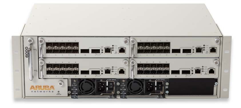
Aruba 6000 Chassis and M3 Mobility Controller Blade
Figure 4 Aruba 6000 Chassis with four M3 Mobility Controller Blades
6000 Chassis with
Feature M3 Blade
Four M3 Blades
Maximum Campus APs 2048 512
Maximum RAPs 4096 1024
Maximum Device Count 32,768 8,192
Concurrent IPsec Tunnels 16,384 4,096
Aruba Networks, Inc. Understanding the Aruba Mobility Controller | 12Aruba Mobility Controllers Validated Reference Design
Aruba 3000 Series Mobility Controller
Figure 5 Aruba 3000 Series Mobility Controllers
Feature 3600 3400 3200XM
Maximum Campus APs 128 64 32
Maximum RAPs 512 256 128
Maximum Device Count 8,192 4,096 2,048
Concurrent IPsec Tunnels 4,096 4,096 2,048
Aruba Networks, Inc. Understanding the Aruba Mobility Controller | 13Aruba Mobility Controllers Validated Reference Design
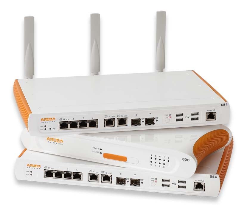
Aruba 600 Series Branch Office Controller
Figure 6 Aruba 600 Series Branch Office Controllers
Feature 651 650 620
Maximum Campus APs 17 16 8
Maximum RAPs 64 64 32
Maximum Device Count 512 512 256
Concurrent IPsec Tunnels 512 512 256
Aruba Networks, Inc. Understanding the Aruba Mobility Controller | 14Aruba Mobility Controllers Validated Reference Design
Understanding the Mobility Controller Master/Local Model
All Aruba Mobility Controllers are capable of assuming two operating roles in the system: master or
local. This hierarchy allows organizations to build scalable WLAN networks with no additional
management platforms as long as the network is contained to a single master/local cluster. A typical
master/local cluster consists of one master mobility controller (or redundant pair) and one or more
local mobility controllers.
Master Backup
master
Local Local
arun_0424
Figure 7 Master/Local Hierarchy
The master is the central point of coordination and configuration of the network. The master processes
all wireless security events and sends policy-based configuration to the locals. The locals manage the
campus APs (CAPs), air monitors (AMs), spectrum monitors (SMs), RAPs, VPN clients, MASs with
tunneled ports, and devices attached to the WLAN. APs connect directly to the local over an IP-based
network, and in most deployments, all traffic from devices is sent to the locals for processing.
Understanding the Master Mobility Controller
The role of the master is to provide a single point of policy configuration and coordination for the WLAN
in smaller deployments. The master can receive configuration and coordination information from the
AirWave for larger or more distributed deployments. In smaller, single-controller deployments, the
master also can perform all functions of the local. The communication channel between the master
and locals uses IPsec. Aruba recommends that APs or clients not be terminated on the master in large
deployments. The master should be allowed to perform the network coordination and control functions.
Master Backup master
Network Local 1 Local 2
Operations
arun_1085
Figure 8 Network services layer
Aruba Networks, Inc. Understanding the Aruba Mobility Controller | 15Aruba Mobility Controllers Validated Reference Design
Masters are responsible for the following functions in the WLAN:
Policy configuration: Configuration in the Aruba solution is split between policy and local
configurations. Local configuration relates to physical interfaces, IP networking, and VLANs,
which are different for each mobility controller. Policy configuration is centered on the operation
of APs and users, including AP settings such as the SSID name, encryption, regulatory domain,
channel, power, and ARM settings. Policy configuration extends beyond APs and also covers
user authentication, firewall policy, mobility domains (IP mobility), IPsec, and system
management. The policy is pushed to all locals in the form of profiles, and profiles combine to
create the configuration for the dependent APs.
AP white lists: Two types of white lists exist in the system, one for RAPs and one for CAPs that
use CPsec. These lists determine which APs can connect to the mobility controllers.
Unauthorized devices are prevented from connecting to the network.
Wireless security coordination: Wireless intrusion prevention activities involve looking for
rogue (unauthorized) APs and monitoring for attacks on the WLAN infrastructure or clients. The
master processes all data collected by Aruba APs and AMs. Instructions to disable a rogue AP
or blacklist a client from the network are issued through the master.
Valid AP list: All mobility controllers in the network must also know all legitimate APs that
operate on the WLAN. These APs must be added to the valid AP list. This list prevents valid APs
from being falsely flagged as rogue APs. This is important when APs that are attached to two
different locals are close enough to hear each other’s transmissions. The valid AP list helps
ARM to differentiate between APs that belong to the network and those that are neighbors.
Unlike traditional wireless intrusion detection system (WIDS) solutions, the master controller
automatically generates the valid AP list without network administrator intervention. All Aruba
APs are automatically learned and added to the list, but valid third-party APs must be added
manually. If more than one master/local cluster exists, AirWave should be deployed to
coordinate APs between clusters.
RF visualization: The Aruba RF visualization tools provide a real-time view of the network
coverage. This information is based on the AP channel and power settings and the data
collected from AMs and APs listening to transmissions during their scanning periods. This
information provides a real-time picture of the RF coverage as heard by the APs.
Location: Locating users in the WLAN is more difficult with mobile clients and IP mobility. The
IP address of the client is no longer synonymous with location. The Aruba WLAN scans off of the
configured channel, so it is possible to hear clients operating on other channels. This information
can then be used to triangulate users and rogue devices to within a small area. This information
is displayed on the master and allows for devices to be located quickly. This speed is critically
important for physical security and advanced services such as E911 calling.
Initial AP configuration: When an AP first boots up, it contacts its master to receive the
configuration generated by the master. The master compares the AP information and
determines its group assignment, and then redirects that AP to the proper local.
Control plane security: When CPsec is enabled, the master generates the self-signed
certificate and acts as the certificate authority (CA) for the network. The master issues
certificates to all locals in the network, which in turn certify APs. If more than one master exists in
the network, the network administrator assigns a single master as the trust anchor for that
network. The trust anchor issues certificates to the other master controllers in the network.
Aruba Networks, Inc. Understanding the Aruba Mobility Controller | 16Aruba Mobility Controllers Validated Reference Design
Authentication and roles: User authentication methods and role assignments are created on
the master and then propagated to locals throughout the network. A database exists to
authenticate users in small deployments or for guest access credentials that can be leveraged
by all the mobility controllers in the network. Additionally, the master can proxy requests for the
network to a RADIUS or LDAP server.
Understanding the Local Mobility Controller
The local mobility controller manages logically attached APs and handles user sessions on the
network. The locals process the majority of the traffic on the network. When the locals manage CAPs,
the locals are typically deployed either in the distribution layer or network data center, depending on
the distribution of traffic in the enterprise. In the case of RAPs, branch office controllers (BOCs), and
Virtual Intranet Access™ (VIA™) agents, the locals are typically located in the network DMZ. In some
networks, the DMZ mobility controllers may be stand-alone masters that also provide local
functionality.
Master Backup master
Network Local 1 Local 2
Operations
arun_1086
Figure 9 Aggregation layer
Locals are responsible for the following functions in the WLAN:
AP, AM, and SM configuration, management, and software updates: All Aruba APs are
dependent APs, which means they do not, in most instances, store configuration settings in the
way that a traditional autonomous AP would. Instead, at boot time each AP downloads its
current configuration from the local. When changes are made in the system configuration, they
are automatically pushed to all APs. Whenever an AP boots, it will always have the current
configuration, and changes are reflected immediately throughout the network. When the
software on the mobility controller is updated, the APs automatically download a new image and
upgrade themselves. This software check, like the configuration download, is part of the AP boot
process, and it insures that each AP has the current operating image and configuration without
user intervention.
Device session termination: An Aruba network is focused on the client devices. In the system
a single user may have multiple devices, each with it’s own sessions and profile. Device
sessions are any information transmitted from a client device across the WLAN. Device sessions
can include human users on a wireless device, wireless IP cameras, medical equipment, and
scanner guns. Every user in an Aruba system is identified when they authenticate to the system
(by WLAN, IPsec, or wired with captive portal), and their login (and optionally device) information
is used to place the device in the appropriate role based on that login. The role of the device
defines what that device, and ultimately the user, is allowed to do on the network. This definition
Aruba Networks, Inc. Understanding the Aruba Mobility Controller | 17Aruba Mobility Controllers Validated Reference Design
is enforced by an ICSA1 certified stateful firewall, and a role-based policy is applied to every
device.
ARM assignments and load balancing: Aruba ARM controls aspects of AP and client
performance. All WLANs operate in unlicensed space, so the chance that something will
interfere with transmissions is very high. Aruba has developed a system to work around
interference automatically and help clients have a better operating experience. These features
include automatically tuning the WLAN by configuring AP power and channel settings, as well as
scanning for better channels and avoiding interference. ARM also handles AP load balancing
and co-channel interference from other APs and clients. Airtime fairness ensures that slower-
speed clients do not bring down the throughput of higher-speed clients. Using band steering,
when the system detects a client that is capable of operating on the 5 GHz band (the majority of
modern clients), the system automatically attempts to steer that client to the cleaner band. More
information on ARM can be found in Aruba 802.11n Networks VRD available at
http://www.arubanetworks.com/vrd.
RFProtect™ security enforcement and blacklisting: While the master handles the
processing of security event information, the local directs the actions of the AMs for enforcement
of wireless security policy. Enforcement can take different shapes, including containing rogue
APs by performing denial-of-service (DoS) attacks wirelessly, ARP cache poisoning on the wire,
shielding valid clients from connecting to rogue APs, and blacklisting clients so that they are
unable to attach to the WLAN.
RFProtect spectrum analysis: When an AP is performing spectrum scanning, the
visualizations of the RF data are generated on the local. This data is pushed to the client’s web
browser and can be saved for later analysis.
CPsec AP certification: When CPsec is enabled in the WLAN, the AP and local mobility
controller establish an IPsec tunnel between the two devices using certificates. The local is
responsible for issuing these certificates and adding APs to the white list. When the AP boots up
and tries to contact the local, the certificates are used to build an IPsec tunnel between the
devices.
Mobility: Supports Layer 2 (VLAN) mobility and Layer 3 (IP) mobility, which allows users to
roam seamlessly between APs on different mobility controllers without session interruption. This
mobility is a key component to support VoIP sessions, where sessions must be preserved.
Quality of service (QoS): The locals support QoS on the wired and wireless side. This support
includes translating DiffServ and ToS bits set on packets into Wi-Fi Multimedia™ (WMM®)
markings and back. The Aruba Policy Enforcement Firewall™ (PEF™) also allows the
administrator to mark packets with the appropriate level of QoS, and to change markings on
packets entering the system.
1. ICSA labs provides vendor neutral testing of products and certifies them in compliance with a set of common tests and criteria.
ICSA is on the web at http://www.icsalabs.com/
Aruba Networks, Inc. Understanding the Aruba Mobility Controller | 18Aruba Mobility Controllers Validated Reference Design
Understanding the All-Masters Model
The all masters model is appropriate where a single controller can handle the entire AP and device
load for the network, or where APs will not be co-located, such as in RAP deployments. This model is
often deployed with AirWave for configuration synchronization and WMS synchronization.
Fundamentally, the network is the same as a master local deployment, but one box does all of the
work.
Redundancy can be handled in one of two ways:
Using master redundancy: When only two boxes exist in the network, master redundancy is
the easiest method to provide a redundant network.
VRRP: When two or more masters exist, VRRP can be used to split the load between the
devices. When the load is split, AirWave is required for WMS offload to keep the AP state
synchronized between controllers. This deployment works in either active-active or N+1
deployments.
In an all-master deployment, APs are spread across multiple mobility controllers, but are in the same
physical location. An all-master deployment must be under the control of a single AirWave instance.
Currently, using ArubaOS 6.1 and AirWave 7.3, these deployments can scale to 5000 devices. WMS
offload must be enabled on the mobility controllers to allow the AirWave to manage valid AP lists.
The following limitations exist in an all-master deployment:
WMS offload must be enabled, but the WMS data is not shared between AirWave instances.
Currently deployments are limited to 5000 devices.
Currently, configuration cannot be synchronized across multiple AirWave instances. If multiple
AirWave servers are required, their configurations must be kept in sync manually.
Depending on polling intervals, it can take some time for AirWave to relearn that users and APs
have moved to a new master. Assume at least one polling cycle before the state is reflected on
the AirWave.
If the status of a device changes on the controller, but it changes again before AirWave polls, the
controller and AirWave may contain different state information. This situation can occur with
classification, but is more likely with user status. If the user roams more than once between
polls, the AirWave will have only the most recent status and will not have the complete trail.
When a failover occurs, and a client that was on the failed controller roams to the new controller,
the client disappears from AirWave until polling finds the client again. The client is not on the
user page on AirWave and is not on the heat map.
Locations that use multiple APs spread across multiple masters result in a wider margin of error
than when a single master/local cluster is enabled.
VisualRF heat maps can take multiple polling cycles to update after APs fail from one master to
the backup master.
Aruba Networks, Inc. Understanding the Aruba Mobility Controller | 19Aruba Mobility Controllers Validated Reference Design
Chapter 3: Controller Licensing
The ArubaOS™ base operating system contains many features and types of functionality that are
needed for an enterprise WLAN network. Aruba uses a licensing mechanism to enable additional
features and to enable AP capacity on controllers. By licensing functionality, organizations can deploy
the network with the functionality to meet their specific requirements in a flexible and cost effective
manner.
License Descriptions
For complete descriptions of the features enabled by these licenses, visit the Aruba website at
http://www.arubanetworks.com/products/arubaos/.
AP Capacity: AP capacity relates to how many APs, AMs, SMs, RAPs, and mesh points that
serve clients can connect to a particular mobility controller. For mesh APs, where wireless is
used for wired traffic backhaul, the mesh links that do not broadcast a client SSID are not
counted against this license. If the AP acts as a mesh node and an access point for devices, the
AP counts against the AP capacity license. When you plan for redundancy, the AP capacity
must match the maximum number of APs that could potentially terminate on the backup mobility
controller.
Policy Enforcement Firewall–Next Generation (PEF-NG): The Aruba PEF-NG module for
ArubaOS provides identity-based controls. The controls enforce application-layer security,
prioritization, traffic forwarding, and network performance policies for wired and wireless
networks. Administrators can build a unified, integrated system for network policy enforcement
by leveraging the open APIs of PEF-NG. External services such as content security appliances,
network access control (NAC) policy engines, performance monitors, and authentication/
authorization servers also can be leveraged by redirecting traffic and accepting authorization
information from the external device. PEF-NG is licensed by AP count, and the number of
licensed APs must be equal to the AP capacity license of the mobility controller. To enable PEF-
NG on wired-only gateways, a single AP PEF-NG license is required.
Policy Enforcement Firewall–VPN (PEFV): The PEFV license provides the same features and
functionality that PEF-NG does, but it is applied to users coming in over VPN connections as
opposed to wireless users. The user role and policy are enforced on the mobility controller and
thus only affects centralized traffic. This license is required for the Aruba VIA client. The PEFV
license is purchased as a single license that enables the functionality up to the full user capacity
of the mobility controller.
RFProtect: The Aruba RFProtect module protects the network against wireless threats to
network security by incorporating multiple scanning and containment features into the network
infrastructure. Integration of WLAN and security provides wireless network visibility and
simplicity of operation for network administrators, and thwarts malicious wireless attacks,
impersonations, and unauthorized intrusions. Clients and APs are already a part of the system,
so no valid AP or user list must be manually maintained because the network already knows
which users and devices belong there. Additionally, many of the traditional features and attacks
that are reported by traditional WIDS vendors are unnecessary due to the RFProtect integration
Aruba Networks, Inc. Controller Licensing | 20Aruba Mobility Controllers Validated Reference Design
with the WLAN itself. RFProtect is licensed by AP count, and the number of licensed APs must
be equal to the AP capacity license of the mobility controller.
xSec™ (XSC): xSec is a highly secure data link layer (Layer 2) protocol that provides a unified
framework for securing all wired and wireless connections using strong encryption and
authentication. xSec provides a Federal Information Processing Standard (FIPS)-compliant
mechanism to provide identity-based security to government agencies and commercial entities
that need to transmit extremely sensitive information over wireless networks. xSec provides
greater security than other Layer 2 encryption technologies through the use of longer keys,
FIPS-validated encryption algorithms (AES-CBC-256 with HMAC-SHA1), and the encryption of
Layer 2 header information that includes MAC addresses. xSec was jointly developed by Aruba
and Funk Software®, which is a division of Juniper Networks®. xSec is licensed on a per-user
basis.
ArubaOS Advanced Cryptography (ACR): The ACR module brings Suite B cryptography to
Aruba Mobility Controllers, which creates a secure and affordable unified access network that
enables mobility for highly sensitive and classified networks. Approved by the US National
Security Agency (NSA), Suite B is a set of publicly available algorithms that serve as the
cryptographic base for both unclassified information and most classified information. The NSA
has authorized the use of Suite B to facilitate the use of commercial technology for mobility as
well as sharing of sensitive and classified information among disparate departments. ACR is
licensed on a per-user basis.
Understanding the Functionality of PEF-NG and PEFV
Table 2 highlights the features that are enabled by each of the firewall licenses as they are installed,
and how they interact with one another.
Table 2 PEF-NG and PEFV Comparison Chart
Wired/
PEF-NG PEFV Wireless Third-
VIA Client Controller Port ACLs
License License Users Party AP
Users
Installed Not Installed Yes No Yes Yes
Installed Installed Yes Yes Yes Yes
Not Installed Installed No Yes No Yes
Not Installed Not Installed No No No Only MAC, EtherType, and
Extended ACLs are supported
Licensing Requirements and Recommendations
Different license capacities are required for master and local mobility controllers. Each license type
should be reviewed to determine if the features and functionality meet the goals of the organization.
With that information it is possible to determine the required feature licensing levels.
Aruba Networks, Inc. Controller Licensing | 21Aruba Mobility Controllers Validated Reference Design
Matching AP-Based Licenses
AP-based licenses should always have the same AP count when in use. These licenses are AP
capacity, PEF-NG, and RFProtect. Backup mobility controllers must have a license for each AP that
the backup will terminate. The licensing rule is:
AP Capacity = PEF-NG = RFProtect
For example, if a 64 AP capacity license was purchased and the organization wants to deploy PEF-NG
and RFProtect, those licenses should be purchased to match the 64 AP capacity. The final license
count would be capacity for 64 APs, 64 PEF-NGs, and 64 RFProtect licenses. There is one exception
to this rule, and that is for the master. If the master does not terminate APs, it does not require AP
licenses.
Licensing Requirements for Master Mobility Controllers
The masters must manage the functionality for all other platforms, so the master must have the same
license types as the locals. Licensing unlocks configuration capabilities on the system. However, the
master will not terminate APs or devices, so the master can be licensed at a much lower level than the
locals, which service APs and devices. Table 3 lists the recommended licensing levels for masters that
do not terminate users.
Only licenses that enable required functionality should be purchased. For
example, xSec is primarily deployed only in government and military
installations, and it is not required unless it will be in use at the organization.
NOTE Before purchasing any licenses, check that the functionality enabled by the
license will be used within the organization.
Table 3 Minimum Licensing Levels for Master Controllers
License Capacity
AP Capacity 0
PEF-NG 1
PEFV 1
RFProtect 1
xSec 1
Advanced Crypto 1
Licensing Requirements for Local Mobility Controllers
Locals must be licensed according to the number of devices or users that consume licenses. Table 4 is
a license consumption table that describes how the different licenses are consumed on locals that
terminate user sessions and APs.
Locals should be licensed at the maximum expected capacity. In a failover scenario, the backup
controller must be licensed to accept all the APs that it could potentially host if a failure occurs, even if
that is not the normal operating level.
Aruba Networks, Inc. Controller Licensing | 22Aruba Mobility Controllers Validated Reference Design
For example, a pair of Aruba 3600 Series Mobility Controllers is operating as locals. Each terminates
40% of the AP capacity, but each acts as the backup for the APs on the other local. Each mobility
controller must be licensed to 80% of maximum capacity. If one local fails, the other must be able to
add the additional APs from the failed local.
Table 4 Licensing Levels for Local Controllers
License Capacity
AP Capacity Any AP (campus, mesh, or remote) that broadcasts an SSID, or any active AM or SM. Mesh APs that do
not broadcast an SSID (such as a point-to-point bridge) do not count against this limit.
PEF-NG Any active AP (campus, mesh, or remote) or any AM or SM. This license must be equal to the AP capacity
of the network.
PEFV PEFV is licensed by box capacity, so licenses are not consumed by individual sessions. Instead, after the
license is installed, all sessions up to the box limit will have a firewall policy applied to them.
RFProtect Any active AP (campus, mesh, or remote) or any AM or SM. This license must be equal to the AP capacity
of the network. To enable spectrum analysis, RFProtect must be purchased.
xSec User sessions using xSec.
Advanced Crypto User sessions using Advanced Crypto.
Aruba Networks, Inc. Controller Licensing | 23Aruba Mobility Controllers Validated Reference Design
Chapter 4: Mobility Controller Operation
Mobility controllers centralize many of the functions that would previously have been pushed to the
edge of the network. Understanding the available options will help the network administrator build an
effective Aruba WLAN.
User VLANs
The VLANs that support user traffic and that the client device uses to receive its IP addressing
information are not always that same as the VLAN that the AP is plugged in to. In many cases, the
user VLAN has nothing to do with the VLAN that the AP is connecting through. The user VLAN
assignment varies depending on the forwarding mode, so each forwarding mode is described here.
User VLANs in Tunnel and Decrypt-Tunnel Modes
In the tunnel and decrypt-tunnel forwarding modes, user traffic flows transparently across the network
in a GRE tunnel. In tunnel mode, device traffic is not converted to an Ethernet frame and placed in a
VLAN until it reaches the mobility controller. In decrypt-tunnel mode, the traffic is decrypted but is still
tunneled using GRE. The user VLAN does not exist at the AP that is providing access, so the VLAN
the user is actually placed into does not need to exist there either.
The wireless traffic is processed at the AP, but because it is sent over a GRE tunnel, the user does not
need to be in the same VLAN as the AP. The easiest way to think of this construct is that the user
essentially is connected directly to the mobility controller. IP addressing is based on a logical design
for the user, as opposed to the physical port that the AP is plugged in to, as is the case with bridge
mode APs. Figure 10 shows an AP attached to an edge switch with a VLAN that extends to the
mobility controller.
Local
mobility
100 100
arun_0239
controller
Figure 10 AP plugged into a local switch, accessing the mobility controller
Aruba Networks, Inc. Mobility Controller Operation | 24Aruba Mobility Controllers Validated Reference Design
In this case the VLANs that the users are assigned to do not exist at the AP. Those VLANs exist only
on the mobility controller itself. This configuration simplifies the edge of the network, because all user
VLANs are not required to reside at the edge switches and they need only be trunked to the mobility
controller. Figure 11 shows the actual VLAN of the users, which exists only from the mobility controller
through the switch to the router.
Local 200
mobility
controller 200
arun_0240
Figure 11 User VLAN, logical connection
The advantage of this design is a simplification of the network and flexibility of terminating users. When
the organization needs additional user VLANs, these can be created only at the switch that connects to
the mobility controllers, and no change must be made to the APs or the network edge.
User VLANs in CAP Bridge Mode
When APs are used in bridge mode, the user VLAN and the AP VLAN are typically the same VLAN,
because this model operates only on a flat Layer 2 network. In this case, the AP is handling the traffic
exclusively for the user and bridging it locally instead of sending the traffic back to the mobility
controller for processing.
AP2
VLAN 100 VLAN 100
VLAN
AP1 AP3
100
VLAN 100
arun_0241
VLAN 100
Client
Figure 12 Users and APs in a bridge mode deployment share the same VLAN
Aruba Networks, Inc. Mobility Controller Operation | 25Aruba Mobility Controllers Validated Reference Design
User VLANs in RAP Bridge Mode
In RAP mode, the RAP can be configured to act as the local DHCP server for any clients that are
attached to bridge mode SSIDs or ports. In this case, a VLAN must be defined on the RAP and the
controller, and an associated DHCP pool must be configured. This configuration is pushed down to the
RAP and is used by any clients that associate to the RAP on a bridge mode connection. The DHCP
scope is local to the RAP itself, so the RAP must perform NAT translation on all traffic leaving the
upstream interface just as a typical gateway router would.
Remote IPsec/AES-CCM encrypted control channel
location Shared
Guest/Family use
SSID printer Enterprise HQ
(Bridge Mode-PSK) LAN PC
Websites
Locally
bridged Enterprise
data Firewall / SSID
NAT-T
RAP Internet or
(with firewall) WAN
Voice
Enterprise SSID
SSID
arun_0243
Voice SSID
Figure 13 User VLANs in RAP bridge mode
Aruba Networks, Inc. Mobility Controller Operation | 26Aruba Mobility Controllers Validated Reference Design
User VLANs in Split-Tunnel Mode
Split-tunnel mode is similar in operation to the tunnel and decrypt-tunnel modes, except that the AP
applies firewall policy at the edge and makes routing decisions for the client. IP addressing is supplied
from the mobility controller centrally. The AP also exists in a local subnet, though this may not be
defined as a VLAN.
IPsec/AES-CCM encrypted control channel
Remote Family Enterprise HQ
location PC
Shared use
printer
Family SSID
(Bridge Mode-PSK) Websites
RAP Enterprise
(with firewall) Firewall / SSID
NAT-T
Enterprise
Internet or
SSID
WAN
(Split Tunnel Voice
Mode-802.1X) SSID
Voice SSID
RNSG_124
(Full Tunnel
Mode-PSK) Enterprise
arun_0244
IP phone
Figure 14 User VLANs in split-tunnel mode
Aruba Networks, Inc. Mobility Controller Operation | 27Aruba Mobility Controllers Validated Reference Design
Guest VLANs
Dedicated guest VLANs are common in networks to limit guest access to other parts of the network
and they take two forms:
VLANs to the DMZ: Limit guest access by using a management construct.
VLANs just at the mobility controller: Limit guest access by using firewall policy.
When the VLAN is run from the controller to the DMZ, users are placed in this VLAN and sent to the
DMZ. Routers in the network forward traffic only to the DMZ and do not allow the users to route to
other VLANs. This action protects the local infrastructure if the VLAN design is secure, but as shown in
Figure 15 it does nothing to stop users from interacting with one another on the same guest VLAN.
DMZ
VLAN 200
Internet
arun_0245
Chat or
file sharing
Figure 15 Guest VLANs without firewall enforcement
Aruba Networks, Inc. Mobility Controller Operation | 28Aruba Mobility Controllers Validated Reference Design
When the Aruba PEF is used, the guest VLAN typically exists only on the local. The local acts as the
DHCP server, and the firewall policy is used to limit user traffic. A typical policy allows the user to
receive DHCP and DNS from the local network. Figure 16 shows that the policy then prevents all other
traffic destined to the local network and allows only Internet access. Typically guest users in this
scenario receive a private, nonroutable IP address, and NAT is performed as their traffic leaves the
controller on a public VLAN.
DMZ
VLAN 200
Internet
arun_0246
Figure 16 Guest VLAN with firewall blocking inter-user traffic
These two delivery mechanisms are not a “one or the other” decision, and they can be combined.
Aruba recommends that role-based firewall policies be applied to guest users even when using a
dedicated VLAN that is routed to the DMZ. For more security, users may want to use GRE tunneling
instead of a VLAN to force clients to the DMZ controller as shown in Figure 17.
DMZ GRE tunnel
Internet
arun_0246b
Figure 17 Guest VLAN with firewall and GRE tunnel to the DMZ
Aruba Networks, Inc. Mobility Controller Operation | 29Aruba Mobility Controllers Validated Reference Design
Dedicated AP VLANs
When wireless networks were first deployed, dedicated AP VLANs were used to segregate the
wireless traffic from other wired traffic. This segregation was done to force wireless traffic through
firewalls and IPsec concentrators to secure wireless connections after WEP was broken. Figure 18
shows this historical view of the reuse of remote networking technologies to protect WEP encrypted
Wi-Fi links.
DMZ
IPsec
concentrator
Data center
Distribution
File
server
arun_0247
Wireless
client
Figure 18 Historical AP VLAN Model
This method leads to management overhead, not only to ensure that each AP is plugged into an “AP
port” on the switch, but also that the switch is configured correctly. The other downside to this
approach is that AMs become less effective, because they can no longer see user traffic that may be
exiting a rogue AP on the wired side of the network.
Aruba Networks, Inc. Mobility Controller Operation | 30Aruba Mobility Controllers Validated Reference Design
The only recommended use for a separate AP VLAN is in networks where 802.1X is configured on the
edge switch to do link layer authentication of users. The AP does not support an 802.1X supplicant, so
it is recommended that the wired switch be configured to place “failed” devices in a special AP VLAN
that only is only routable to the mobility controller as shown in Figure 19.
Network
VLAN 100 VLAN 100
802.1X
Network
VLAN 300
VLAN
802.1X 300
fails
arun_0248
Figure 19 Users with 802.1X configured are able to pass,
APs are placed in an AP only VLAN
and routed to the mobility controller
Aruba Networks, Inc. Mobility Controller Operation | 31Aruba Mobility Controllers Validated Reference Design
Quarantine VLANs
Quarantine VLANs are common in networks where network access control (NAC) has been
integrated. Devices that have failed their health check are put into the quarantine VLAN until they can
be brought in-line with policy. The problem with this traditional method is that a set of infected stations
in the same VLAN tends to lead to more infections as seen in Figure 20. If the users are able to
remediate, they must then be moved back to the “production” VLAN and receive a new IP address.
DMZ
Internet
Some
attempted
200
traffic
Remediation
Server Distribution
200
Access
Viruses
Viruses
arun_0249
Figure 20 Quarantine VLAN does nothing to stop cross-device infection
Aruba Networks, Inc. Mobility Controller Operation | 32Aruba Mobility Controllers Validated Reference Design
Instead, Aruba recommends that the PEF-NG firewall be used to put users into a quarantine role. This
role should allow stations to access only remediation resources, either locally or on the Internet. These
resources could include antivirus vendors, operating system vendors, and software vendors. All other
traffic should be denied, which removes the ability of the station to infect other users as seen in Figure
21. After the station is remediated, it does not need to reboot or renew its IP address because the
station does not switch VLANs. The user simply is placed in the production role and allowed to use the
network fully.
DMZ
Internet
Traffic
200
Remediation
server Distribution
200
Access
arun_0250
Figure 21 Using the firewall to limit the spread of viruses in the remediation role
Aruba Networks, Inc. Mobility Controller Operation | 33Aruba Mobility Controllers Validated Reference Design
VLAN Pools
Network administrators prefer to keep subnet sizes down to a Class C size network. This network has
a subnet mask of /24, which yields up to 253 user devices per subnet. This size is considered
manageable and helps to limit the broadcast domain size. In networks where this subdivision needs to
be logical as opposed to physical, VLANs are employed to limit broadcast domain size. The issue
arises when enough users exist to exceed a single subnet, which is a common occurrence because
the WLAN has gone from a convenience network to a part of the critical network infrastructure.
The traditional methodology for dividing up large groups of wireless users is to place a set of APs in a
VLAN and have all devices associated with those APs placed into that single VLAN as shown in Figure
22. This method works if the user count never goes above the subnet user count limit and if users have
no need to roam outside of the AP group. This method limits the size of a subnet, and it is typically
deployed only in small networks with a single subnet.
Mobility
controller
VLAN 10 VLAN 40
arun_0251
VLAN 20 VLAN 30 arun_048
Figure 22 VLANs spread across groups of APs
However, this method tends to fail when large groups of users need to meet in a single location like a
lecture hall, or an “all hands” meeting, or where roaming across APs is likely to occur. The individual
subnets will have their IP pools exhausted, leading to devices being unable to connect. This becomes
even more problematic as smartphones and tablets show up along side laptops and connect to the
network.
Aruba Networks, Inc. Mobility Controller Operation | 34Aruba Mobility Controllers Validated Reference Design
The Aruba VLAN Pooling feature allows a set of VLANs to be assigned to a designated set of virtual
APs. These VLANs can be configured as a noncontiguous set, a contiguous range, or a combination of
the two as shown in Figure 23. For example, the set could be VLAN numbers 10, 20, and 30. The set
could also be VLAN numbers 2 through 5. These methods can be combined to provide a set such as
3, 5, and 7 through 10. This flexibility allows you to assign users to VLANs that may already exist in the
enterprise. VLAN pools are the method that Aruba recommends for handling user VLANs any time two
or more user VLANs are needed to handle the user load from a single set of APs going to a single
mobility controller.
Mobility
controller
arun_0252
VLANs 10, 20, 30, 40 arun_049
Figure 23 VLAN pools distribute users across VLANs
The system works by placing users in one of the VLANs in the pool. VLAN placement is determined
using the user MAC address and running it through a hash algorithm. The output of this algorithm
places the user into one of the VLANs in the pool and ensures that the user is always placed into the
same pool during a roaming event. As the user associates with the next AP, their address is hashed
and they are placed into the same VLAN on the new AP. The user can continue to use their existing IP
address with no break in their user sessions. This feature requires that the same VLAN pools be
deployed on all controllers that will service these clients.
Aruba Networks, Inc. Mobility Controller Operation | 35Aruba Mobility Controllers Validated Reference Design
Packet Sizing
Wherever possible the network should be configured to support jumbo frames to avoid fragmentation
of the packets. When this configuration is not possible due to lack of hardware support, the maximum
MTU should be configured on all devices. This setting is especially important for video transmissions,
because the loss of key video frames can cause the entire packet to be retransmitted. It is also
important that transmitters are aware of the frame size limitations. For instance, video servers should
be configured to use the maximum MTU of the network to limit their packet size to the network-
supported maximum and avoid fragmentation.
Default Gateways and Routes
Users terminate on the Aruba Mobility Controller, so there can be some debate about where the
default gateway should exist and how routing table updates should occur. This section describes the
options for deploying the mobility controller as the default Layer 3 gateway as opposed to a Layer 2
device. Also discussed is how user subnets should be routed if the controller is selected as the
gateway.
Layer 2 Deployments
In a Layer 2 deployment, the mobility controller is a “bump in the line” for user traffic. Wireless sessions
are inspected by the firewall and forwarded to the appropriate VLAN, but the mobility controller is not
the default gateway as shown in Figure 24. This deployment model is typically used in campus
networks where an existing Layer 3 switch is already functioning as the default gateway and makes
routing decisions for the network. This deployment model is recommended where multicast routing will
occur.
Router Default gateway
10.1.100.1 10.1.100.1
VLANs 100, 101,
102, 103, 200
Default gateway arun_0253
Figure 24 Mobility controller in a Layer 2 deployment
Aruba Networks, Inc. Mobility Controller Operation | 36You can also read