PROFINET Safety for the future - Products Diagnosis Monitoring Training Consulting - Indu-Sol
←
→
Page content transcription
If your browser does not render page correctly, please read the page content below
Indu-Sol GmbH – Specialist in Industrial Networks

    PROFINET
Safety for the future

                          Products
                        Diagnosis
                     Monitoring
                           Training
                      Consulting
Notes

        2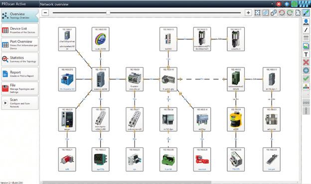
networks
                                                                                                                                                 our passion,  Your Business

Content

          Industry 4.0 – New challenges for automation.................................................... 4

          Basics........................................................................................................................................................ 6

          Standards and guidelines.................................................................................................. 7

          PROFINET Design Guideline and Commissioning Guideline............................ 7

          Parameters for network planning................................................................................. 8

          PROnetplan network planning software................................................................. 10

          ETHERtest V5 and PROlinetest cable tester.......................................................... 12

          PROscan®  Active V2 acceptance test and validation software....................13

          PROFINET-INspektor ®  NT analysis and diagnostic tool.................................... 17

          PROFINET DiagnosticDUO (PROscan® Active V2 & PROFINET-INspektor ® NT )..................... 21

          EMCheck® LSMZ I leakage current measuring clamp......................................... 22

          PROFINET Diagnostic set.................................................................................................22

          iPNMA intelligent measuring point...........................................................................23

          PROmanage®  NT network monitoring software....................................................24

          Configuration example (permanent network monitoring)........................... 27

          PROFINET Switches PROmesh P9 and P20..............................................................28

          PROFINET Switches PROmesh FX and P7X..............................................................30

          PNMA II / PNMX PROFINET measuring points...................................................... 31

          PROFINET services............................................................................................................... 32

          Product overview

          Network planning................................................................................................................ 33

          Analysis | Diagnostics | Measurement.................................................................... 33

          Permanent network monitoring.................................................................................. 35

          EMC (Analysis | Diagnostics | Measurement)...................................................... 35

          Infrastructure components............................................................................................ 35

          PROFINET tools..................................................................................................................... 37

          Services (Measurement | Training)...........................................................................38

                                                                                        3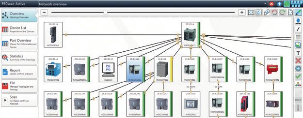
PROFINET in the context of Industry 4.0

 Industry 4.0 – New challenges for automation
The 4th industrial revolution – also known as Industry 4.0 – describes a development where production companies increase the
degree of networking and automation in their value creation chain so high that intelligent machines and systems can process
digital product information automatically for the most part and increasingly organise processes autonomously. In this manner,
even single pieces can be manufactured according to individual sizes (so-called batch size 1) within a reasonable economical
range and thus open up new markets.

                                                                                                                                                     Complexity
                                                                                                                    4. Industrial Revolution
                                                                                                                    Based on cyber-physical
                                                                                                                    systems

                                                                                    3. Industrial Revolution
                                                                                    Automation, introduction of
                                                                                    electrical controllers and IT
                                                                                    systems

                                                   2. Industrial Revolution
                                                   Mass production, use of
                                                   electrical energy

                   1. Industrial Revolution
                   Introduction of production
                   methods, use of water
                   power, steam engine

                  End of the                      Beginning of the                   Beginning of the               Present                          Time
                  18th century                    20th century                       1970s

 Fig. 1: Schematic presentation of the four industrial revolutions                                                                                                Source: DFKI

Prof. Dr. Henning Kagermann (German Academy of Sciences),                                 In practical application, it is becoming clear that Ethernet-
Prof. Dr. Wolf-Dieter Lukas (Federal Ministry for Education and                           based networks such as PROFINET will gradually replace field-
Research) and Prof. Dr. Wolfgang Wahlster (German Research                                bus technology and thus become the pathfinder for Industry
Centre for Artificial Intelligence) went public in 2011 with                              4.0 at the production level (operational technology, OT).
the “Initiative Industry 4.0” and thus coined a term that has                             Networks, which still have a mostly local structure today, will
found rapid increased use since. By establishing the “Plat-                               in the future grow together from the classically hierarchic
form Industry 4.0” (2013) for the coordination of the deve-                               structure of the automation pyramid into a large, complex
lopments, the federal government has declared this as a topic                             network of decentralised distributed intelligences (so-called
for top management.                                                                       cyber-physical systems, CPS) (see Fig. 2 and 3).

        Corporate
        management level     Corporate
                             management level
        Operations
        management level     Operations
                             management level
        Process
        management level     Process
                             management level

        Control
        level                Control
                             level
                                                        Real-time
         Field                                          critical              Real-time
         level                Field                                           critical
                              level
                           Automation pyramid                                                          CPS-based automation
                                                Automation pyramid                                                            CPS-based automation
 Fig. 2: Automation pyramid                                                                 Fig. 3: CPS-based automation                                           Source: VDI

                                                                                      4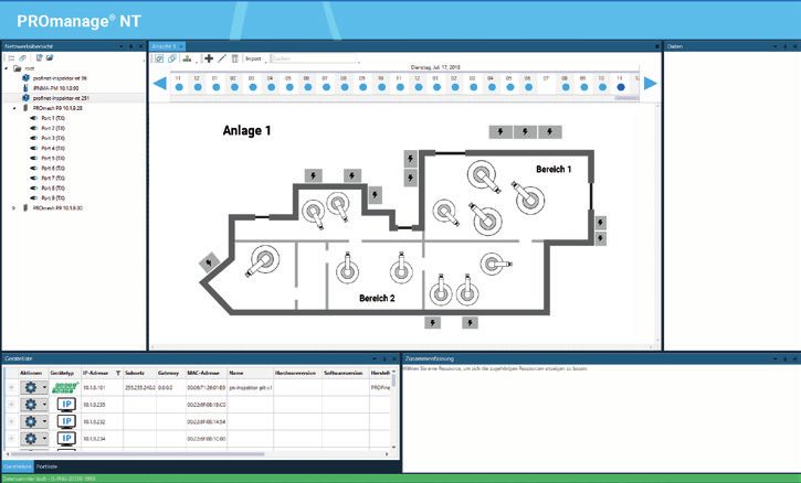
networks
                                                                                                   our passion,  Your Business

In the face of a vast array of solutions offered by industrial        singly controlled by data that is provided by intelligent sen-
Ethernet-applications, the challenge lies in finding a common         sors and devices. This data can be retrieved directly from
system without communications obstacles that satisfies all            the office level (information technology, IT), which likewise
requirements. It is becoming clear that in the future more            communicates via Ethernet. External (unauthorised) access is
interest will be focussed on standard Ethernet and different,         possible just as well however.
parallel existing protocols will drop away. The IEEE task force
TSN (Time Sensitive Networking) was created to give real-             In order to understand data flows under the conditions of an
time capability to standard Ethernet.                                 increasing blending of IT and OT and to ensure security, it is
Security aspects are gaining importance as well (see below).          becoming increasingly important to know:
Thanks to the advances of digitisation, production is increa-         Who communicated what with whom when by which means?

Security for Automation 4.0
The blending with IT however does not permit the accep-               whole world. The events need to be recorded though to
tance of its security measures for the automation tech-               recognise their causes and to even notice such attacks.
nology. The task for IT is rather to prevent unauthorised             Today‘s approach by Indu-Sol is based on the log analysis
external access to data whereas automation technology                 by permanent network monitoring (PNM). In combination
places its focus on attacks „from inside“. Whether they               with the network monitoring software PROmanage® NT
are own staff or visiting service technicians – they can,             (see page 24), the passively operating measurement and
possibly even unintentionally, cause quality-relevant in-             diagnostic tool PROFINET-INspektor® NT (see page 17)
cidences by supposedly harmless actions such as an acti-              thereby analyses the logical data traffic in the network.
ve network scan or the loading of firmware updates.                   Anomalies, such as unknown participants in the network
                                                                      or delays in the data transmission (so-called jitters, see
Currently such accesses to the network cannot be regu-                page 8), are reported immediately.
lated without endangering its availability. The correct
concept by IT of shielding off to the outside for pro-                When these quality-relevant events are recorded additio-
tecting the data is, however, in direct contrast to the               nally and kept on hand, the operator knows at any time
point of view of automation technology with its idea of               what is going on in his network.
increasing networking of customers and producers in the

                                                                  5
What is PROFINET ?                                                                                                       PROFINET - The Movie | Technology Made Easy
                                                                                                                                     www.indu-sol.com/profinet-movie or use the QR code directly

  Basics
PROFINET is a universal, Ethernet-based communication network that can be used in all areas of automation technology.
Speedy vertical and horizontal data exchange across all levels – including the corporate control level – is the foundation for
successful systems concepts.

                                                                                                                        Ethernet (MES)

                                                                                                Engineering
                                            Controller 1             Controller 2                                             Sensor              Robot
                                                                                                  station

                                                                                                                                                          PROFINET RT / IRT

                                                                                                                                                            Proxy
                                  Drive unit                  Drive unit               Drive unit            I/O link      Remote
                                                                                                                                          Transmitter                    Proxy
                              manufacturer A              manufacturer B manufacturer C                      master          I/O

                                                                                                                                           PROFIBUS DP                           Proxy

                                                                                                                                                   PROFIBUS PA

                                                                                                                                                             Fieldbus...
 Fig. 4: PROFINET overview

Like PROFIBUS, PROFINET distinguishes between acyclical                                                                 Data in PROFINET networks is highly varied. Besides priori-
and cyclical data communication (RT – Real Time) and addi-                                                              tized, cyclical PROFINET I/O data, acyclical data (e.g. TCP/
tionally supports fast I/O communication (IRT – Isochronous                                                             IP, diagnostic messages or SNMP requests) can be transmitted
Real Time). This is done while retaining the familiar design                                                            (see Fig. 6).
with a cyclical transfer of peripheral data between the field
devices (IO devices) and the process image in the IO control-
ler. This results in a high degree of flexibility because update                                                                                                            PROFINET IRT (1+2+3)

rates are scalable (see Fig. 5).                                                                                                                  PROFINET RT (1+2)

                                                                                                                          Standard Ethernet (1)

                                                                                                                                                        Process data                  Process data
                                                                                                                               IT services
                                                         Printing machines                                                                                  (RT)                          (IRT)
                                      Robots, presses,
                                     packing machines
               Tool machines, assembly lines,                                          Highest demands and
                                                                                                                               TCP / UDP
                 warehousing and logistics                                             performance reserve

              10 ms                                    1 ms                            100 µs                                       IP
Bus cycle

            TCP/IP         Real Time (RT)                                  Isochronous Real Time (IRT)                                                    Ethernet                       Ethernet
                                                                                                                                Ethernet
 Acyclic data
 Diagnostic informations
                              Standard I/O
                              Simple drive solutions
                                                               Quick I/O
                                                              Motion Control
                                                                                                                                                        + priorization               + synchronization
                                                                               250µs                     31,25 µs
                                                       PROFINET
                                                                                                                          1                        2                             3

 Fig. 5: Scalable bus cycle times (RT and IRT) in PROFINET                                                               Fig. 6: Three communication channels in PROFINET

PROFINET describes a device model that is based on the                                                                  Network topologies in PROFINET derive from the requirements
principles of PROFIBUS and consists of slots and groups of                                                              of the systems to be networked. The most common structures
IO channels (sub-slots). The technical characteristics of the                                                           are star, line, tree and ring-shaped. In practice, systems usu-
field devices are described by a so-called GSD (General Stati-                                                          ally are a mix of the above structures. They can be implemen-
on Description) that is based on XML.                                                                                   ted either with copper or fiber-optic cables.

                                                                                                                    6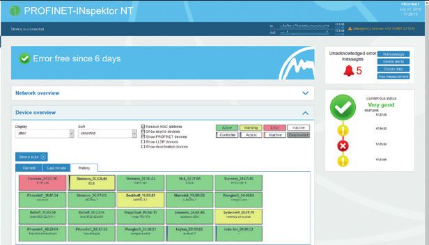
networks
                                                                                                       our passion,  Your Business

 Standards and guidelines
  Criteria for quality evaluation in the PROFINET are based on the following list of standards and guidelines as well as the experience
  of Indu-Sol GmbH. Observing them is the basis for any measurement, planning, acceptance inspection and commissioning.
         ■■ PROFINET Design Guideline - Version 1.14 - December 2014
         ■■ PROFINET Commissioning Guideline – Version 1.36 – December 2014
         ■■ PROFINET Assembly Guideline – Version 1.0 – January 2009
         ■■ PROFINET I/O Security Level 1 (netload) – Version 1.2.1.1 – February 2017
         ■■ PROFINET Conformance Classes – Version 1.1 – March 2011
         ■■ EN 50173 / ISO IEC 11801 – Structured cabling systems
         ■■ EN 50310 – Application of equipotential bonding and earthing in buildings with
            information technology equipment
         ■■ VDI / VDE Guideline 2184 – Reliable operation and maintenance of fieldbus systems
         ■■ Functional grounding and shielding of PROFIBUS and PROFINET – Version 1.0 – March 2018

 PROFINET Design Guideline and Commissioning Guideline
The extensive options for configuration and utilization                The selection and placement of network components in
of a network necessitate careful planning and practice-                the network structure depends on the performance of the
oriented commissioning of the system. The user organiza-               devices. It is described by the net load classes (IO Securi-
tion PROFIBUS & PROFINET International (PI) has defined                ty Level 1 – see the “standards and guidelines” box).
quality criteria for planning, acceptance and commissio-
                                                                       The years of experience with fieldbus technology have
ning, as well as the metrological evaluation of a network
                                                                       shown that the extensive diagnostic options of controllers
in its latest Design and Commissioning Guideline. It
                                                                       in the area of device diagnostics should be expanded by
is intended as a guideline for all persons and organiza-
                                                                       an additional measurement to verify the quality of com-
tions involved in the planning, installation, operation and
                                                                       munication. The measurements serve as dual purpose, na-
maintenance of such systems.
                                                                       mely a description of the PROFINET network on the one
In the planning stage, network utilization should be                   hand and ensuring operational reliability on the other.
considered in addition to structure. For this purpose, it              Special attention should be paid to assuring the quality of
is important to know the relationships between update                  the line connections (test when plant is stopped) as well
rate, line depth and network structure. Practical planning             as the transmission during operation.
tools like PROnetplan by Indu-Sol can be used to display
such relationships in an interactive graphic to avoid weak                    RECOMMENDATION
spots.
                                                                        In order to ensure reliable long-term functionality of the
Moreover, it is useful to define the requirements for IO                plant, measurements to verify compliance with the quality
devices in advance. The categorization in Conformance                   requirements (pages 9 and 19) are urgently recommended.
Classes (CC-A, CC-B, CC-C) is a useful aid to users when
selecting devices that have no more than the requi-
red functionality. Requirements include simulta-
neous access to devices by several controllers
(IO controllers), support for media redundan-
cy, detection of topology information in the
network, device exchange without repea-
ted use of a parameterization device, as
well as applications with very short
cycle times and low variation.

                                                                   7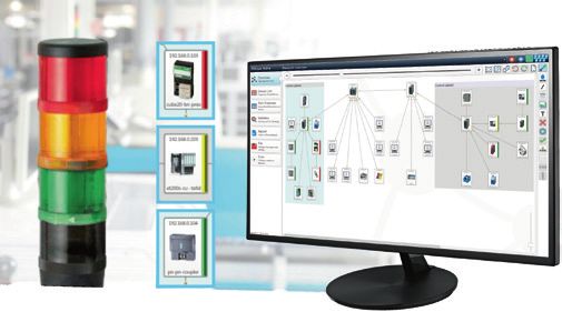
PROFINET planning
Parameters for network planning
Planning the network structure Netload
The key properties of PROFINET are a variable network struc- The cyclical netload generated by each PROFINET device has
ture and the unlimited combinations provided by exploiting a maximum in the connection between the controller and
all topological shapes of the standard Ethernet. The topology the first device. In order to permanently ensure the flawless
results from the following criteria: functioning of the PROFINET network the following tolerances
for planning and realization have to be ensured:
■■ Spatial arrangement of the components
■■ Distances to be bridged Netload Recommendation
■■ Requirements for the use of primary infrastructure / < 20% No action required
increased availability 20% ... 50% Review of planned netload is recommended
■■ Consideration of netload (netload planning) and
> 50% Take action to reduce netload
TCP/IP traffic
■■ Update rate in consideration of line depth It can be seen from the practical applications that the
■■ Communication quality and telegram traffic existing netload consists of both PROFINET and TCP/IP
■■ Requirements for potential isolation/EMC communication. Although the PROFINET communication is
generally prioritized at switches (network nodes), TCP/IP
Selecting the right topology is important for the further
communication may sometimes jump the queue. Whether
planning of a PROFINET automation system. If required,
and to what extent this happens – or can happen – can be
the topology has to be adapted in a later inspection step.
seen from the load ratio (PROFINET to TCP/IP communica-
Sources: PI Design Guideline (V 1.14 / Dec. 14) pp. 51-56
PI Commissioning Guideline (V 1.36 / Dec. 14) pp. 91/92 tion). Since different netloads (peak loads) affect the com-
pliance with update rates and devices of different netload
Update time
classes are especially sensitive to peak loads demonstrating
The update rate is the interval at with the data between the
the network quality in consideration of utilization is espe-
controller and IO device is updated. It can be set individually
cially important during the acceptance test or troubleshoo-
for each device in the controller (standard setting: 2 ms). In
ting of a system.
addition to considering the requirements of the process, also
Sources: PI Design Guideline (V 1.14 / Dec. 14) pp. 115-118
consider the PLC cycle time. Indu-Sol recommends setting PI Commissioning Guideline (V 1.36 / Dec. 14) pp. 95/96
the update time for devices to at least half the PLC cycle
time. The guiding principle is “Update only as necessa-
ry – not as much as possible.“ The switching behavior of 30%
each device and the installed line depth, i.e. the number
of passing devices (switches and IO devices with integrated
40% 10%
switches) on the line, are critical for compliance with the up- 10%
10% 40%
date rate. An increasing number of passing devices prolongs
the duration of the telegram. The variation of the real from 40% 5% 5% 40% 5%
the set update rate keeps increasing. It is called “jitter” and 40% 40%
Video Video
indicated in percent. Measurements to show compliance with display camera
Fig. 8: TCP/IP devices are connected unfavorably → higher netload
the set update rates and their variation may serve as a basis
for an assessment of system stability and provide an early
warning of potential weak spots.
Sources: PI Design Guideline (V 1.14 / Dec. 14) pp. 97-99
PI Commissioning Guideline (V 1.36 / Dec. 14) p. 104 30%
40% 40%
1,2 ms
1 ms 1 ms
Video 10% Video
display camera
10%
10%
5% 5% 5%
TCP/IP telegrams
PROFINET telegrams
Fig. 7: Illustration of telegram jitter Fig. 9: TCP/IP devices are connected optimally → low netload
8
networks
                                                                                                                                                        our passion,  Your Business

                                                                                                                        PN-INspektor® NT     PNMA  II     iPNMA     PROmesh P9             PROnetplan

Line depth
Because in PROFINET (RT) it cannot be determined whe-
                                                                                                                                                                      Fig. 10: Line depth example
ther a device (switch) is operating in store-and-forward or
in cut-through mode a delay has to be expected for every
passing device.
                                                                                                                    1                  2                  3                    4

This delay has to be considered when designing a network                                                                                                                       5
in the planning phase. Fundamentally, the maximum line
depth depends on the update time and the switch mode                                                                                                                           6
(see the “line depth” tables). Indu-Sol recommends obser-
ving the values from the PI guideline “Line depth for store-                                                                                                                   7                    8
and-forward switches”.
                                       Source: PI Design Guideline (V 1.14 / Dec. 14) pp. 111-114

Line depth for store-and-forward switches                                                               Line depth for cut-through switches
                 Max. line depth for update time of                                                                         Max. line depth for update time of
      1 ms                2 ms                   4 ms                         8 ms                           1 ms                      2 ms                       4 ms                         8 ms
        7                  14                     28                            58                            64                       100                        100                          100

Access points
When planning PROFINET networks the guideline recommends passive access points for network diagnostics.
Why?                                                                                                    Please note:
■■ During commissioning or maintenance, to analyze the net-                                             In principle, an initial rough analysis of the network traffic
   work traffic or read out devices                                                                     (telegram analysis) is also possible via a mirror port on the
■■ To connect diagnostic devices during running operation                                               switch using analysis software (e.g. Wireshark). However,
   without interruption                                                                                 this port only delivers 100 Mbps.
■■ For troubleshooting or long-term diagnosis/preventative                                              But the cable carries incoming data to the controller at
   maintenance of the network condition                                                                 100 Mbps on one wire pair and outgoing data from the
How?                                                                                                    controller at 100 Mbps on the other wire pair. Thus the port
■■ Using passive, feedback-free TAPs                                                                    of the switch cannot diagnose more than one half of the
   (e.g. PROFINET measuring points PNMA  II / PNMX − see page 31)                                       data flow.
                                                                                                                                                          Source: PI Design Guideline (V 1.14/ Dec.  14) pp. 90-91
■■ Using a smart TAP
   (e.g. PROFINET-INspektor® NT / iPNMA − see page 17, 23)
                                                                                                              RECOMMENDATION – Quality values
                                                                                                         Recommendations on the quality values in PROFINET by Indu-Sol
                                                                                                                                           Jitter
                                                                                                                (deviation from the planned update time)
                                                                                                                                                                                              < 50 %
                                                                                                                                                                                              −

                                                                                                                                   Telegram gap
                                                                                                                                  (missing telegram)                                                0

                                                                                                                                  Error telegram
                                                                                                                                (defective telegrams)                                               0

                                                                                                                                     Load ratio
                                                                                                                    (How heavily the network is loaded?)                                      100 : 1

                                                                                                                                       Netload
                                                                                                                                     (in 100 Mbps)                                            < 20 %
 Fig. 11: Network diagnosis via access point (TAP) – e.g. PNMA II

                                                                                                    9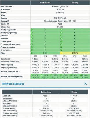
PROFINET planning

 PROnetplan network planning software
PROnetplan is a software for the preliminary planning of                               about the impact on net load when integrating compo-
industrial networks. The network can be assembled intu-                                nents with TCP/IP communication. As in real hardware
itively on a graphic interface. Important parameters like                              configuration the update rate can be set uniformly for all
the net load at the controller are calculated and displayed                            devices or separately for each device. Security pop-ups
automatically based on the line depth and the preset up-                               show the locations in a network where the use of a firewall
date rate. With a simple simulation of the communication                               would be advisable.
parameters or changes in the network structure, potential
bottlenecks can be identified and eliminated during the                                In addition to network optimization, the topology created
planning stage. All devices and the predicted net load for                             with PROnetplan may serve both as a platform for dis-
each interface are listed in a clear overview. Free switch or                          cussion with the customer and as a document for network
device ports as well as the line depth are shown for each                              installation.
device. A special feature is the automated notification

  Device type Device name Number of ports              Free ports     Netload (Byte)         Netload generated (%)    Local netload (%)   Allocated controller
  Controller    Controller 1     2                    1                                  0                           7,4
  Switch        Switch 1         8                    4                                  0                           7,4
  Switch        Switch 2         8                    6                                  0                           2,56
  Switch        Switch 3         8                    5                                  0                           4,84
  Uplink        Uplink 1         1                    0                                  0                           0
  IO Device     IO Device 1      2                    0             56                   0,64                        2,56                 Controller 1
  IO Device     IO Device 2      2                    0             56                   0,64                        1,92                 Controller 1
  IO Device     IO Device 3      2                    0             56                   0,64                        1,28                 Controller 1
  Switch        Switch 4         8                    6                                  0                           1,92
  IO Device     IO Device 5      2                    0             56                   0,64                        1,92                 Controller 1
  IO Device     IO Device 6      2                    0             56                   0,64                        1,28                 Controller 1
  Switch        Switch 5         8                    6                                  0                           2,92
  IO Device     IO Device 8      2                    0             56                   0,64                        2,92                 Controller 1
  IO Device     IO Device 9      2                    0             56                   0,64                        2,28                 Controller 1
  IO Device     IO Device 4      2                    1             56                   0,64                        0,64                 Controller 1
  IO Device     IO Device 7      2                    1             56                   0,64                        0,64                 Controller 1
 Fig. 12: All devices are shown in a clear device list (including all relevant parameters)

                                                                                 10
networks
our passion, Your Business
PROnetplan
Automatically generated detail information:
Netload Network access
PROnetplan dynamically shows the re- All net access devices are shown in the
sulting load for every connection in the software and can be considered in the
network. This also applies with complex planning phase.
network structures or networks with
multiple controllers.
Update time Free ports
The update rate can be set uniformly for Displays remaining free ports on swit-
all devices or separately for each device. ches and devices.
Line depth
PROnetplan shows the line depth dyna- Payload
mically for each device. The communi-
cation partner can be assigned for every For a more accurate calcu-
device in the network. lation of the netload the
real payload can be set for
Highlights each device in the expan-
ded view.
■■ Display of the netload for every connection in the network
Security information
■■ Update rate setting
■■ Indication of line depth for every device The user-friendly pop-ups with security
■■ Separate netload settings for each device information show immediately which
devices have free ports that may need
■■ Definition of different network access devices, e.g.
to be blocked and where the use of a
PROFINET-INspektor® NT or the measuring points iPNMA,
PNMA II, PNMX firewall might be advisable.
■■ Clear device list for all devices
■■ Pop-ups with security information PROnetplan in conjunction with PROscan® Active V2
The topologies scanned with the PROscan® Active V2 analysis
■■ Display of remaining free ports on switches and devices
software (see page 13) can easily be fed into PROnetplan.
■■ Full-featured printer functionality This enables a comparison between the plan and reality. This
■■ PDF export with numerous functions procedure is very useful during planning an expansion or
optimization of the network.
11PROFINET acceptance | analysis | diagnostics
ETHERtest V5 and PROlinetest cable tester PROlinetest ETHERtest V5
Certification and acceptance
The ETHERtest V5 (V5.1/ V5.2) cable tester provides for all
measurements required for the acceptance and certification
of network cables up to Class FA /Category 6A (1000 MHz). Not
only line length but also attenuation, resistance, crosstalk
(NEXT), delays, shielding and the proper contacts (connec-
tion schematic) are measured and evaluated. Beyond the
certification of copper cables, attenuation and OTDR can
be measured for single and multi-mode fiber optic cables by
means of additional adapters (ETHERtest V5.1).
All recorded values are displayed graphically, which enables
Fig. 13: ETHERtest V5
the error sources to be identified and localized with an
accuracy of 10 centimeters. All measurements are stored
automatically in the device and can be retrieved as measu-
rement report using PC software.
Verification and troubleshooting
PROlinetest is an indispensable tool for all those who ins-
tall or troubleshoot PROFINET systems. The device detects
any wiring errors and tests the wires and wire pairs for con-
tinuity, breaks, short-circuits, cross-wiring and exceeded
maximum cable lengths.
The measurement of the total cable length and the distance
to the error location significantly simplifies troubleshoo-
ting. The adapter can also be used to check Drive-Cliq and
M8/M12 cable systems.
Fig. 14: PROlinetest
Source: PI Commissioning Guideline (V 1.36 / Dec. 14) pp. 47-62
RECOMMENDATIONS – Evaluation based on cable length
Compliance with the limits set out, for example, ISO IEC 11801 means that weak spots are not detected in advance. This is why all
Class D, is always evaluated over a maximum distance of 100 m by measuring equipment should be evaluated based on length in ac-
the measuring equipment, e.g. 24 dB insertion loss. This means cordance with the tables below in regard to the reserve insertion
that in case of shorter cables (e.g. 10 m), it is also only com- loss and the near-end crosstalk. By assessing the reserve, this pro-
pliance with an insertion loss of 24 dB that is monitored, which cedure is independent from the standards and limits that are used.
Length-dependent Min. near-end crosstalk Length-dependent
Max. insertion loss acc. Length-dependent min. Length-dependent min.
Cable length recommended min. Cable length acc. to class D f or recommended min.
to class D f or 100 MHz insertion loss near-end crosstalk
insertion loss 100 MHz near-end crosstalk
100 m 24 dB 0 dB 3 dB 100 m 30 dB 0 dB 3 dB
50 m 24 dB 3 dB 6 dB 50 m 30 dB 3 dB 6 dB
25 m 24 dB 6 dB 9 dB 25 m 30 dB 6 dB 9 dB
12 m 24 dB 9 dB 12 dB 12 m 30 dB 9 dB 12 dB
6m 24 dB 12 dB 15 dB 6m 30 dB 12 dB 15 dB
3m 24 dB 15 dB 18 dB 3m 30 dB 15 dB 18 dB
1,5 m 24 dB 18 dB 21 dB 1,5 m 30 dB 18 dB 21 dB
The qualitative evaluation of insertion loss (IL) should be performed while The qualitative evaluation of the near-end crosstalk (NEXT) should be per-
taking the line length into account. formed while taking the line length into account.
12networks
our passion, Your Business
PROscan® Active V2 acceptance test and validation software PROscan® Active V2
Online analysis / topology scan
Highlights
With the PROscan® Active V2 software you can generate a
detailed description of your PROFINET networks online during ■■ Easy to use
running production at any time. Thanks to PROFINET devices‘ ■■ Diagnostics mode
integrated LLDP protocol (detection of neighborhood rela • Connection statistics
tionships) it is possible to generate a complete topology map • Version statistics
• EMC statistics
including all designations and connections in an extremely
short time, and thereby simultaneously perform an initial ■■ Acceptance report
simple diagnosis (line interruptions, device failures etc.) du- ■■ Asset Management
ring operation. Other strengths of this product include flexi-
■■ Network / device information
ble options for integration into existing plants and a simple,
• Current port assignments
intuitive user interface. • Port operating mode
• Port speed
The software helps to efficiently organize a complex network • Device version / name
• IP- / MAC addresses
and, if required, perform necessary maintenance in a time-
• Software / Hardware versions
ly and direct manner. Its low resource requirements enable • Error telegrams
PROscan® Active V2 to be installed on any commonly availa- • Rejected telegrams (discards)
ble touch panel.
■■ Suitable for PROFINET and Ethernet networks
Source: PI Commissioning Guideline (V 1.36 / Dec. 14) pp. 91/92
Advanced printing and export functions (PDF) comprehensive documentation options
Fig. 15: PROscan® Active V2 - clear visualization of the network topology
13PROFINET acceptance | analysis | diagnostics
PROscan® Active V2 acceptance test and validation software
Device list
In addition to the device information (manufacturer, ordering device names, IP and MAC addresses accordingly. The evalua-
details), the automatically generated device list also gives tion of this data can be exported into an acceptance-relevant
a quick overview of the hardware and firmware versions of log or for documentation as a CSV file at the push of a button.
all devices used (including device extensions), allocating the
Device Device type Controller RealTime PROFINET
Actions IP adresses Subnet Gateway MAC adress Device name HW version SW version Order number
type name name Class Rolls
172.20.1.51 255.255.255.0 172.20.1.51 00:1B:1B:72:7E:89 x208-cu-zeile4 6 V4.5.0 SCALANCE X-200 6GK5 208-0BA10-2AA3 controller-tafel RTClass2 Device
172.20.1.54 255.255.255.0 172.20.1.54 00:A0:45:68:20:F9 phoenix-switch-zeile3 5 V3.80.0 FL SWITCH SMCS 2989103 controller-tafel RTClass2 Device
8TX-PN
172.20.1.55 255.255.255.0 172.20.1.55 00:1B:1B:34:83:A6 x202-pof-zeile2 5 V5.0.22 SCALANCE X-200 6GK5 202-2BH00-2BA3 controller-tafel RTClass2 Device
172.20.1.56 255.255.255.0 172.20.1.56 00:1B:1B:1E:1B:21 et200s-pn-pof-zeile3 2 V7.0.1 IM151-3 6ES7 151-3BB23-0AB0 controller-tafel RTClass2 Device
172.20.1.58 255.255.255.0 172.20.1.58 00:0E:8C:D7:E3:32 x208-cu-zeile1 4 V4.5.1 SCALANCE X-200 6GK5 208-0BA10-2AA3 controller-tafel RTClass2 Device
172.20.1.59 255.255.255.0 172.20.1.59 00:1B:1B:24:DA:80 et200m-pn-zeile1 2 V4.0.0 IM153-4 6ES7 153-4AA01-0XB0 controller-tafel RTClass2 Device
172.20.1.60 255.255.255.0 172.20.1.60 00:1B:1B:3A:EC:7E x208-cu-zeile5 6 V4.5.1 SCALANCE X-200 6GK5 208-0BA10-2AA3 controller-tafel RTClass2 Device
172.20.1.64 255.255.255.0 0.0.0.0 00:80:63:66:54:B0 octopus-zeile7 130 V4.2.3 Hirschmann 6GK5 208-0BA10-2AA3 controller-tafel RTClass2 Device
OCTOPUS
172.20.1.65 255.255.255.0 172.20.1.65 00:16:77:00:8F:A1 pn-asi-gw-zeile5 2 V2.0.0 AS-i BWU1912 controller-tafel RTClass2 Device
Slot Subslot Modul ID Submodul ID Vendor-ID Order number Serial number HW version SW version
1 1 0x00016001 0x00000000 42 6ES7 155-5AA00-0AC0 S C-HONX24052016 2 V3.0.1
2 1 0x00006D20 0x00000003 42 6ES7 521-1BH00-0AB0 S C-HDMX36262016 3 V2.1.2
3 1 0x00006D18 0x00000003 42 6ES7 522-1BH01-0AB0 S C-HDNK33432016 1 V1.0.0
172.20.1.71 255.255.255.0 172.20.1.71 00:90:E8:3D:1D:BD eds-510e 100 V4.0.0 MOXA EtherDevice 0054-000510-E000 controller-tafel RTClass2 Device
Switch
172.20.1.74 255.255.255.0 172.20.1.74 00:01:05:16:EE:87 bk9103 BK Device Device
Port overview
In addition to the device list with all device-relevant data, a Information on error telegrams or rejected telegram packets
list of port relevant data for each device is also available. The (CRC error or discards) is important for detecting weaknesses
overview shows both the cable lengths of copper and polymer and to perform an error analysis.
fiber connections as well as the attenuation reserve of poly-
mer fiber connections.
Send Remote
Number Name Connected with Line type Length Connection InDiscards OutDiscards
power budget power budget
172.20.1.200 (controller-tafel)
2 port-002 172.20.1.55 (x202-pof-zeile2) Copper ca. 58,6m 100BaseTXFD 0 78
172.20.1.54 (phoenix-switch-zeile3)
1 port-001 172.20.1.60 (x208-cu-zeile5) Copper 17,2m 100BaseTXFD 0 0
2 port-002 172.20.1.51 (x208-cu-zeile4) Copper 47,1m 100BaseTXFD 0 0
3 port-003 172.20.1.248 (inblox) Copper 5,0m 100BaseTXFD 0 0
4 port-004 172.20.1.82 (ASi-INspektor) Copper 5,0m 100BaseTXFD 0 0
5 port-005 172.20.1.81 („PB-INspektor V2“) Copper 5,0m 100BaseTXFD 0 0
172.20.1.55 (x202-pof-zeile2)
1 port-001 172.20.1.200 (controller-tafel) Copper ca. 58,6m 100BaseTXFD 0 0
2 port-002 172.20.1.71 (eds-510e) Copper 10,5m 100BaseTXFD 0 0
Fibre-optic
3 port-003 172.20.1.56 (et200s-pn-pof-zeile3) 20,5m 4,2 dB 10,8 dB 100BaseTXFD 0 0
Cable
172.20.1.56 (et200s-pn-pof-zeile3)
Fibre-optic
1 port-001 172.20.1.55 (x202-pof-zeile2) 20,5m 10,8 dB 4,2 dB 100BaseTXFD 0 0
Cable
14networks
our passion, Your Business
PROscan® Active V2
Explanations (Discards/Error telegrams)
Data packets may be discarded by the switch, e.g. because
of malfunctions, transmission errors or queue overflow at the
switches.
PROscan® Active V2 determines the number of such discards
15%
(rejected telegram packets) and the number of defective te- 10% 5%
legrams (CRC errors) from the devices and displays them in a
table. This provides clues as to potential causes of error.
5% 5% 5%
During the analysis of such information special attention needs
to be paid to devices in communication lines with high load,
e.g. Switches of the primary infrastructure. (see Fig. 16)
Fig. 16: Reading out switch components for discards
Source: PI Commissioning Guideline (V 1.36 / Dec. 14) pp. 93/94
Checking the system reserve for optical cabling
If using polymer optical fiber (POF), the optical system
reserve (power budget) of every single connection can be
determined in online operation. It is a measure for the
available optical power reserve between transmitter and
receiver to ensure trouble-free operation. It can be read
out and displayed as a diagnostic value. If the attenuation
reserve of a POF connection falls below 5 dB, it is immedi-
ately apparent where transmission problems might occur.
These are represented by an exclamation mark in the
PROscan® Active V2
connection. This enables you to detect and remedy the
weaknesses in your system at any time.
Source: PI Commissioning Guideline (V 1.36 / Dec. 14) pp. 88/89
System reserve Evaluation
The value is above the measurement range.
> 6 dB
No action required.
The value is within the valid measurement range.
Trouble-free communication is ensured.
Typical values for cabling without other plug-in
connections:
• 5 dB for cable lengths up to 30 m
> 2 dB to 6 dB • 3,5 dB for cable lengths from 30 m to 40 m
• 2,5 dB for cable lengths from 40 m to 50 m
In case of deviation from the listed value ran-
ges a cable inspection is recommended (check
for additional plug-in connections, attenuation
Fig. 17: Display when transmission problems occur check).
15PROFINET acceptance | analysis | diagnostics
PROscan® Active V2 acceptance test and validation software PROscan® Active V2
Diagnostics mode IP-Adress Device Port Value
Connections/Ports with IN DISCARDS
An overview immediately shows the user all anomalies de- 10.1.9.5 fl-switch-ghs port-001-00009 2
10.1.9.6 bk9103-1-1 port-001 4
tected by the network scan. In the connection statistics, for 10.1.9.6 bk9103-1-1 port-002 164
10.1.9.18 bnipnt502102z015-1 port-001 187206
example, device ports are listed with accumulated discards 10.1.9.18 bnipnt502102z015-1 port-002 383429
10.1.9.19 bnipnt502102z015 port-002 427308
or error telegrams as well as a too low optical fibre system 10.1.9.21 wenglor-cam port-001 2
reserve. Additionally, a statistic of the software and hardware 10.1.9.94 iPNMA Pa???? 6
10.1.9.96 profinet-inspektor-nt port-passive 4
statuses of all devices (including device extensions) quickly 10.1.9.97 PN-INspektorNT5 port-passive 17
Connections/Ports with IN ERRORS
reveals whether there are discrepancies between devices of 10.1.9.2 pn-io port-002 869365
10.1.9.3 scalance-x208 port-003 874391
the same type. 10.1.9.3 scalance-x208 port-005 949
10.1.9.3 scalance-x208 port-006 21172
10.1.9.4 fl-switch-smcs-8tx-pn port-001 23
Main modules Order number SW Version HW Version Num. of devices 10.1.9.5 fl-switch-ghs port-001-00009 4
AXL BK PN-ME 2688132 V1.2.0 5 1 10.1.9.15 im153-4pn-1 port-002 1
V2.2.0 5 1 10.1.9.17 helmholz-pn-switch port-001 1
BNI PNT-502-102-Z015 BNI006C
V2.3.0 5 1 10.1.9.17 helmholz-pn-switch port-004 1
Cube20S 57106 V1.3.6 1 1 10.1.9.18 bnipnt502102z015-1 port-001 1189
ET200SP 6ES7 155-6AU00-0CN0 V3.1.0 4 1
10.1.9.21 wenglor-cam port-001 3
FL SWITCH GHS 4G/12 2700271 V2.62.0 6 1
FL SWITCH SMCS 8TX-PN 2989103 V4.40.0 5 1
10.1.9.62 mobmesse-x208 port-004 59
FTS3100-A 20781104000 V2.2.2 256 1 10.1.9.96 profinet-inspektor-nt port-passive 17
Helmholz PN-Switch 700-850-4PS01 0 1 10.1.9.97 PN-INspektorNT5 port-passive 22
IM151-3 6ES7 151-3BB23-0AB0 V7.0.5 3 1 Connections with too low attenuation reserve
IM153-4 6ES7 153-4AA01-0XB0 V4.0.0 2 1 10.1.9.9 im151-3pn port-001 16,4
PN-INspektor NT 124030100 1 Connections/Ports with OUT DISCARDS
PROscanActive 117000014 2.0.0.218 1
10.1.9.17 helmholz-pn-switch port-001 60
S7-300 GES7 318-3FL01-0AB0 V3.2.6 5 1
10.1.9.17 helmholz-pn-switch port-003 49
V5.1.0 6 1
SCALANCE X-200 6GK5 208-0BA10-2AA3 10.1.9.17 helmholz-pn-switch port-004 330474
V5.1.3 6 1
SICK-S3000PROFIsafe 1064234 V1.11.0 0 1 10.1.9.21 wenglor-cam port-001 5
WAGI-I/o-SYSTEM 75x 750-370 V2.5.10 4 1 Connections/Ports with OUT ERRORS
wenglor ident weQube V1.1.4 100 1 10.1.9.21 wenglor-cam port-001 6
Fig. 18: Version statistics Fig. 19: Connection statistics
Acceptance log
PROscan® Active V2 is able to create a complete acceptance log with only a few clicks.
xcerpt
Log e
Fig. 20: Clear overview of all important information – this includes all system information (e.g. records of EMC conditions in the bus environment)
16networks
our passion, Your Business
PROFINET-INspektor® NT analysis and diagnostic tool PN-INspektor® NT
The PROFINET-INspektor® NT is an intelligent, passive Network parameters – Quality parameters
measurement and diagnostic tool for temporary or perma- User-friendly display of network conditions with traffic light
nent monitoring of PROFINET networks. Due to its passive colors and time graphs enable any user to respond quickly in
and feedback-free behavior it is highly suitable for online an emergency and ensure a good general overview.
analysis.
The PROFINET-INspektor® NT is both a full-featured measu- All subsequently listed quality parameters are detected as
ring device for network acceptance and a tool for condition events, evaluated, cached and displayed in a clear overview.
monitoring.
■■ Telegram gaps ■■ Network load
Highlights ■■ Telegram jitter ■■ Load ratio
■■ Ease of use, well-structured handling ■■ Telegram overtakes ■■ Device diagnoses
■■ Automated evaluation through traffic light function ■■ Error telegrams ■■ Device failures
■■ Update times ■■ Device restarts
■■ Passive, feedback-free diagnostics
■■ Cyclical topology detection
■■ OPC UA Server Start time: 23.07.2015 16:06:22
End time: 23.07.2015 16:06:33
■■ Alarms in case of unknown devices Siemens_24:DA:80 (192.168.0.10)
Telegram jitter 112%
■■ Network anomaly detection Alert (low priority) 1
PhoenixC_38:5F:34 (192.168.0.6)
■■ Detection of programming accesses to the PLC Failures 1
Murrelek_FE:B9:DE (192.168.0.16)
Telegram gaps 1
Telegram gaps
Telegram jitter
Telegram overtakes
Error telegrams
Update times
Network load
Load ratio
Device diagnoses
Device failures
Device restarts
PROFINET-INspektor® NT
17.2 % 102.8 % 7.6 % 1.1 % 10.0 %
9.2 % 1.0 % 79.7 % 2.5 % 5.0 %
4.1 % 8.5 % 10.1 % 6.4 % 75.9 %
10.3 % 11.7 % 0.1 %
Fig. 21: Clear, detailed device overview with selection of each network parameter
17PROFINET acceptance | analysis | diagnostics
PROFINET-INspektor® NT analysis and diagnostic tool
Device information Netload visualization (see Fig. 22)
Zu jedem Teilnehmer sind alle notwendigen Parameter abrufbar. While other diagnostic devices determine the network load by
the second or even the minute, the PROFINET-INspektor® NT
measures netload by the millisecond and displays it. This
makes even minimal load changes in a network detectable.
Even in the millisecond range peak loads may cause signifi-
cant disturbances in the network which would not be detec-
table without this analysis.
Such short-term peak loads may be caused, e.g. by erroneous
hardware settings or active diagnostic tools that continuously
send queries into the network.
The network should always be monitored for a consistent
netload and any sources of disturbances should be removed.
Continuous, passive analysis as provided by the PROFINET-
INspektors® NT is an indispensable prerequisite.
Please note:
According to the current certification guideline PROFINET de-
vices are tested and specified with a maximum load per mil-
lisecond between 1 and 10%, depending on the netload class.
Source: PROFINET I/O Security Level 1 (Netload) – Version 1.2.1 – March 2016
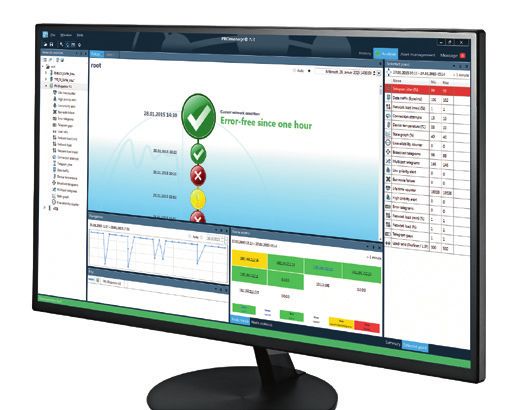
Topology determination
The PROFINET-INspektor® NT not only
determines all relevant device informa- 10.1.9.2
tion (device details and port statistics),
pn-io
but even the real wiring (topology). 2
1
This can also be done remotely without 10.1.9.29 10.1.9.28 10.1.9.3 10.1.9.5 10.1.9.20 10
1 3 6 1 2 13 14 5 1 2
having to establish a direct network cube20s
7
scalance-x208 fl-switch-ghs wenglor-switch
bnipn
2 4 8 6 5 3 4 15 2 1 9 4
access via a service computer or HMI. 1 1 2 1 7 3 1 1 1
c
10.1.9.22 10.1.9.27 10.1.9.24 10.1.9.15 10.1.9.10 10.1.9.207 10.1.9.17 10.1.9.26 10.1.9.9 10.1.9.21 10
The scan can easily be started and sa- 1
ved remotely or by using the integrated et200mp et200sp pn-pn-coupler
2
im153-4pn-1
1
axl-pn-bk
4
scalance-xc-200
1
helmholz-pn-
switch ilb-pn-dio im151-3pn-ps wenglor-cam
bnipn
webserver of the INspektor® from the
ca. 0,2 m
1 1 1 1 1 2
10.1.9.25 10.1.9.16 10.1.9.96 10.1.9.190 10.1.9.31 10.1.9.11 10.1.9.12
own company network. The determined
pn-pn- profinet- EMV-INspektor
topology can then be conveniently ope-
coupler-1 IE-PB-Link inspektor-nt EMFA V2 festo-cpx cube20s-1 s3000
ned and evaluated on your own compu-
Fig. 22: Topology determination with the PROFINET-INspektor® NT
ter using the software PROscan® Active
V2 (see page 13). In addition to manual topology determi- these in a trackable form. These topologies are recorded
nation, there is the option to set up a regular scan in order centrally with the help of the software PROmanage® NT (see
to detect changes in the network structure and the devices page 24) and remain accessible for a period of up to one
integrated into the network in good time and to document year.
18networks
our passion, Your Business
PN-INspektor® NT
2 3
Controller 1 2
Switch Switch
Fig. 23: Integration of the PROFINET-INspektor® NT in the PROFINET network
Trigger function − Alarms
Trigger functions enable the set-
ting of quality parameters for the
network as a whole, but also indi-
vidually for each device if required.
In the event of changes that ex-
ceed the preset thresholds alarm
messages (SNMP, OPC UA, email,
web interface) are sent or displayed
directly via a potential-free con-
tact. The PROFINET-INspektor® NT
has an integrated web server and
a freely selectable IP address. This
enables a visualization of the net-
work condition by means of an Internet browser on any PC, on
site or remotely. RECOMMENDATION – Quality values
In addition to each alarm message telegram copies are stored
Recommendations on the quality values in PROFINET by Indu-Sol
on the INspektor® and can be downloaded via the web interface
for a more detailed error evaluation. Jitter
(deviation from the planned update time)
< 50 %
−
Telegram gap
(missing telegram) 0
Error telegram
(defective telegrams) 0
Fig. 24: Display of alarms in the overview screen Load ratio
(How heavily the network is loaded?) 100 : 1
User-friendly display of network conditions with traffic light
Netload
colors and time graphs enable any user to respond quickly in (in 100 Mbps) < 20 %
an emergency and ensure a good general overview.
19PROFINET acceptance | analysis | diagnostics
PROFINET-INspektor® NT analysis and diagnostic tool PN-INspektor® NT
Touchscreen
The display serves primarily to show the current status of settings are needed to connect to the web interface and
the network and the accumulated faults. This information to view further detail information. Notes on firmware and
makes it possible, without an additional computer, to make hardware versions can be accessed via the display as well.
an assessment about the status of the network.
Much important system information of the PROFINET- Navigation between the individual windows is done by touch
INspektors®
NT is displayed as well. Thus the network control via the arrow buttons.
Acceptance log
Just like with PROscan® Active V2, the PROFINET-INspektor® NT provides the option to have a comprehensive acceptance log
generated with just a few clicks.
xcerpt
Log e
Fig. 25: Clear overview of all important information – this includes all system information (e.g. records of EMC conditions in the bus environment)
20networks
our passion, Your Business
PROFINET DiagnosticDUO (PROscan Active V2 & PROFINET-INspektor NT) ® ®
PROFINET DiagnosticDUO
Combined, the PROscan® Active V2 software and the passive
data collector PROFINET-INspektor® NT form the perfect navi-
Highlights
gation system for your network: the PROFINET DiagnosticDUO. ■■ First user-friendly topological visualization of in-depth
network analysis
Thanks to the teamwork between a live topology map and a ■■ Continuous analysis of the communication quality
diagnostic display the position of each device can be found (network load, telegram gaps, jitter etc.)
immediately and its “health status” can be assessed. This ■■ Device status is indicated graphically with traffic-light
enables you to respond promptly and directly to any irregula- colors in the topology
rities. Intuitive traffic-light colors provide a network analysis ■■ Retrieval of current device list (PROFINET name, IP/MAC
at a glance. address, hardware/software versions, device types etc.)
PROFINET DiagnosticDUO
Interaction of diagnosis and topology – PROFINET DiagnosticDUO
By activating the function “Read out PROFINET-INspektor® NT” in the PROscan® Active V2 software, you can combine the
recordings of both tools. This gives you a navigation system for your PROFINET network so you can see the status of all
devices displayed graphically with traffic-light colours in the topology.
Fig. 26: Information from the topology with PROscan® Active in conjunction with the evaluated quality parameters of the PROFINET-INspektor® NT
21PROFINET acceptance | analysis | diagnostics
EmCheck® LSMZ I leakage current measuring clamp EmCheck® LSMZ I
Ever more often, compensating currents
caused by high-frequency shielding currents
17
AUTO
create intermittent faults in industrial data
mA
communication systems. On one hand, these
WIDE
currents may disturb the transmission itself.
On the other, they may damage the devices by
overloading. Because such effects of high shielding currents are
only noticeable after a some time has passed, it is useful to
define limits and document compliance even for new systems.
The EmCheck® LSMZ I leakage current clamp meter is designed
Shielding currents during running operation should be lower
EmCheck® LSMZ I
specifically to measure leakage and shielding currents in the
than 40 mA.
frequency range of 50/60 Hz or 5 Hz - 1 kHz. The adjustable
measurement range can be set between 30 μA and 100 A. For
RECOMMENDATION measuring shielding currents on a data cable, the lower end
Independently of the system specification, experiences of the range is more relevant. The EmCheck® LSMZ I leakage
at Indu-Sol show that shielding currents ofnetworks
our passion, Your Business
Intelligent PROFINET measuring point iPNMA iPNMA
The intelligent PROFINET measuring point iPNMA combines
the functions of a PROFINET measuring point with a simple
Highlights
PROFINET network analysis. The following quality parameters
■■ Monitoring all important PROFINET quality values
are determined:
■■ Reactionless measurement point
■■ Telegram jitter
■■ Telegram gaps ■■ Compact design
■■ Telegram overtakes ■■ In case of a power supply failure, the PROFINET
■■ Network load communication remains intact
■■ Update rate ■■ Power supply of additional analytic tools via the UOUT
■■ Device diagnoses (24 V DC) connector
■■ Device failures and restarts
■■ Error telegrams General properties PN-INspektor® NT iPNMA
Passive network access (TAP)
In this case, the evaluation of the recorded data does not 24 V supply for additional device
(PN-INspektor® NT)
take place on the device itself, but instead all data is queried
Number of monitored participants 512 256
and processed by the PROmanage® NT software (see page 24) Decoding of DCP / PROFINET parameters
and processed accordingly. Monitoring of non-PROFINET communication
Evaluation of the recorded data
In addition to the integrated diagnostics function, an ana-
PROmanage® NT
lysis tool (e.g. PROFINET-INspektor® NT or laptop) can be Touch display showing the network status and further
information
connected completely reactionless to the two monitor jacks
Webinterface
(monitor M1 and M2) for a more thorough network analysis
Diagnostics mode with PROscan® Active V2
or troubleshooting.
e®
nag
Process network / OT network ma
PRO NT
(Ethernet) ver
Ser
OPC
SNMP request
iPNMA iPNMA
PROFINET PROmanage® NT
Fig. 27: Integration of the iPNMA measurement point in the PROFINET network and evaluation of the data via PROmanage® NT
23PROFINET permanent network monitoring
PROmanage® NT network monitoring software
For preventative, condition-oriented maintenance of
PROFINET networks Indu-Sol has developed a strategy for
Highlights
permanent network monitoring (referred to as PNM in the
■■ Central monitoring of all fieldbuses and networks
following). It provides for condition monitoring with the
goal of “warning before failure”. ■■ Avoid system failures
■■ Timely warning via OPC, SNMP trap or email in case
The concept of PNM provides for a continuous network ana- of irregularities
lysis with a decentral, passive data collector, the PROFINET- ■■ Data exact to the minute available up to one year
INspektor® NT. Whenever preset threshold values are excee-
■■ Quick installation
ded this event is stored together with a time stamp. The
installation is between the controller and the first switch ■■ Easy device set-up due to automatic and manual
device scan
port. Each controller therefore requires an INspektor®.
With PROmanage® NT all external INspektors® are integra-
ted in the monitoring via the existing Ethernet network, To improve system availability the following targets are set
and the network conditions are bundled centrally on a for a PNM system:
server. The network-specific events are pre-processed by ■■ Continuous monitoring of real communication
the PROFINET-INspektor® NT and provided chronologically ■■ Complete monitoring and detection of causes of
by the PROmanage® NT network monitoring software for network weaknesses
further processing and evaluation. ■■ Automatic alarms when negative developments occur
■■ Central overview of all networks
PROmanage® NT enables the evaluation, analysis and long-
term storage of condition data for your fieldbuses and
other industrial networks. For this purpose PROmanage® NT
retrieves the port statistics of manageable switches and
the events of the decentral data
collectors (INspektors®), evaluates
them and displays them graphically.
This sophisticated method of analy-
sis makes irregularities immediately
apparent. When a value exceeds or
falls below a configurable threshold
value an alarm activates. The sta-
tistic function keeps data exact to
the minute available up to one year.
This means historical events can be
opened up for viewing at any time
for cause analysis, e.g. of sporadic
failures.
24networks
our passion, Your Business
PROmanage® NT
Topology
The software PROscan® Active V2
and/or a decentralised data coll-
ector such as the PROFINET-
INspektor® NT determine the to-
pologies of the individual net-
works. With the help of the soft-
ware PROmanage® NT, these can
be recorded at a central point,
can be bundled, and therefore be
displayed to the user in a clear
manner, including all device infor-
mation and statistics that were ob-
tained. This creates a permanent,
up-to-date, and real overview over
which devices are located where
in the network and what their sta-
tus is. This allows for the affected
devices being located quickly in
case of incidents in the network. If
Fig. 28: Central topology detection in PROmanage® NT
changes are made to the wiring of
the network, the respective times can be determined through added devices as well as changes in port allocation of the
the continuous recording of the topology. The anomalies that switches in question.
can be detected in this manner include removed and newly
Plant layout
In order to get a better overview of the real plant layout, layout (see Figure 29). This function allows for the mapping
individual devices in the topology can be allocated to in- of complete assembly lines or a complete floor plan, so that
dividual system parts or installation locations for example, a central contact point is available for the condition moni-
control cabinets, robots, etc. This allows for a comparison toring system.
of the determined network structure with the real system
Sie sind hier: Halle 5 Sie sind hier: Anlagenübersicht › Anlage 7263 mit Informationsfenster › Schaltschrank XYZ
Hall 5 Filter Plant 7263 with information window 1
7648
ex7181
Anzeigen:
7115
7213
7216 Anlage 1ex7112
7212
7254/2
7216 7115
7380
7213
7380
gen 7213 Im Grundriss anzeigen Informations
7121
ex7112
7112
7121
7380
7254
Ansicht anpassen
7138
7387
7216
7544
7532
7150 7492
7263 7648
7875
7173
7279
7156
7252
7380 7369
7648
7377
7163
7532
Position: Plant 1,
7380
7263 7263 7263
7212
Area 1,
Switch cabinet XY
7648
7642
7156
7380
7532
7212
7544
Show Possible Show Edit
7461 7472 7150 7472
topology sources of error History Errors
Fig. 29: Display of the recorded network structure in the real plant layout
25You can also read