Assembly Manual Agile 1P - PRODUCT SPECIFICATION - Trina Solar
←
→
Page content transcription
If your browser does not render page correctly, please read the page content below

PRODUCT
                         SPECIFICATION
                                 Document AM
                                     Revision 1
                                Date 7/23/2021

Assembly Manual
Agile 1P

STANDARD MANUAL

ENGINEERING DEPARTMENT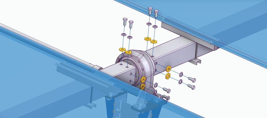
ASSEMBLY MANUAL
AGILE 1P
                                                        Document AM | Date 23/07/2021 | Revision 1 | Page 1 de 38

                        REVISION CONTROL

              DATE
   REV                    DESCRIPTION      ELABORATED                 REVISED                 APPROVED
           (dd/mm/yy)

    1      23/07/2021   INITIAL DOCUMENT

                                              LGA                       AGS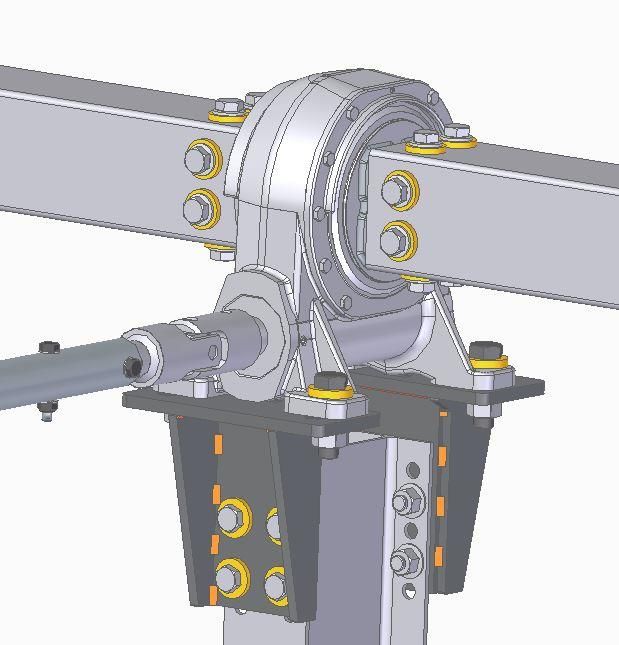
ASSEMBLY MANUAL
AGILE 1P
                                                                                Document AM | Date 23/07/2021 | Revision 1 | Page 2 de 38

              CONTENT
              1   Agile 1p tracker overview ...........................................................................................4

                  1.1.    Agile 1P solar tracker. .............................................................................................................4

                  1.2.    Tracker’s main elements ........................................................................................................5

              2   Tools and machinery list ..............................................................................................6

                  2.1.    Auxiliary machinery ................................................................................................................6

                  2.2.    Site survey equipment ............................................................................................................6

                  2.3.    Tools..........................................................................................................................................6

                  2.4.    Auxiliary gear ..........................................................................................................................7

              3   Torque tightening values .............................................................................................8

              4   Tracker layout and foundations – posts (motor & standard) ................................10

                  4.1.    Tracker topographic layout ................................................................................................. 10

                  4.2.    Posts identification and distribution ..................................................................................... 10

                  4.3.    Tracker’s foundation. Typologies. Driving ........................................................................... 11

                                       Trackers foundation design .................................................................................... 12

                                       Direct ramming or pre-drilling foundation ............................................................. 12

                                       Tracker foundation execution sequence .............................................................. 14

                                       Post driving tolerances ............................................................................................ 15

              5   Specific component assembly .................................................................................18

                  5.1.    Motor post – slewing drive support – slewing drive system ............................................... 18

                  5.2.    Standard post – bearing support – bearing system ........................................................... 20

                  5.3.    Rotation axis (tubes) system ................................................................................................ 21

                  5.4.    Breaking plate assembly ...................................................................................................... 25

                  5.5.    Purlin fixing system (Trina clamp or other type) ................................................................. 26

                  5.6.    Transmission bar system ....................................................................................................... 29

                  5.7.    Purlin – Module fixing system ............................................................................................... 31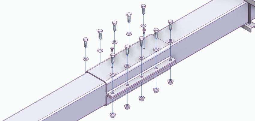
ASSEMBLY MANUAL
AGILE 1P
                                                                          Document AM | Date 23/07/2021 | Revision 1 | Page 3 de 38

                  5.8.   End cups assembly ............................................................................................................... 32

              6   Tracker control unit (TCU) and self-powered system assembly. ..........................33

                  6.1.   Tracker control unit or TCU assembly .................................................................................. 33

                  6.2.   Self-powered system assembly ........................................................................................... 34

              7   Grounding strap assembly. Equipotentiality of the structure. ...............................35

              8   Anemometer tower and other sensors assembly ..................................................36

              9   Network control unit (NCU) assembly .....................................................................37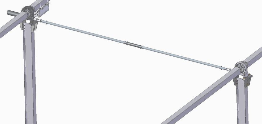
ASSEMBLY MANUAL
AGILE 1P
                                                              Document AM | Date 23/07/2021 | Revision 1 | Page 4 de 38

           1      AGILE 1P TRACKER OVERVIEW

           1.1.   Agile 1P solar tracker.

                  The AGILE 1P tracker is a double-row tracker, with rotational drive with slewing drive (Motor on
                  the first row and motorless in the second one) that moves the torque tube and the purlin system –
                  Upper module, commanded by the Tracker’s Control System (TCU) that guides the movement of
                  the tracker with an algorithm that optimizes the energy production and the solar tracking
                  efficiency.

                  The tracker’s set that compounds a park, has protection against certain weather events,
                  generally wind and snow, through a box of sensors and alarms, that thanks to the System’s
                  General Controls (NCU) drive the trackers to pre-parameterized defense position on each case.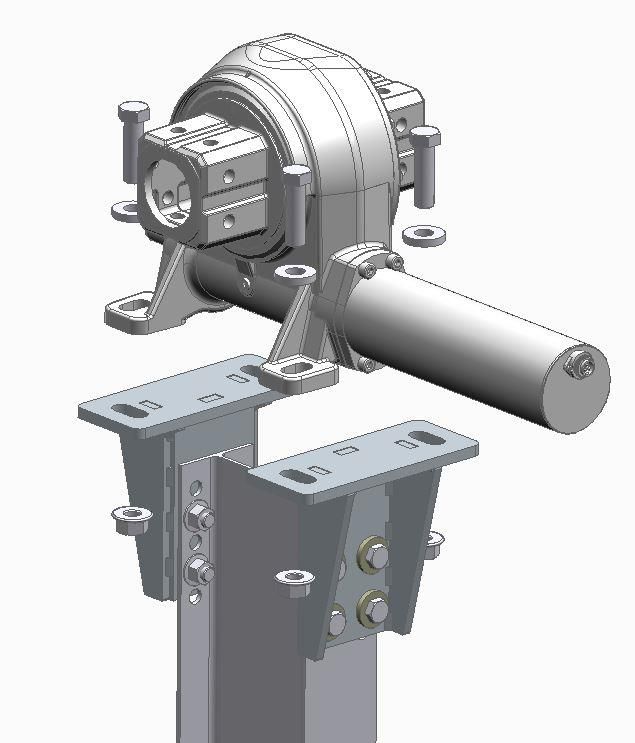
ASSEMBLY MANUAL
AGILE 1P
                                                            Document AM | Date 23/07/2021 | Revision 1 | Page 5 de 38

           1.2.   Tracker’s main elements

                                                                              Slewing drive

                            Transmission bar

                                                                    Motor pile
                            Slewing drive support

                                                                    Bearing          Square profile joining

                                                          Module

                                                                                                Trina clamp
                                                            Standard pile
                                                                                        Bearing support

                                                    Illustration 1: Main elements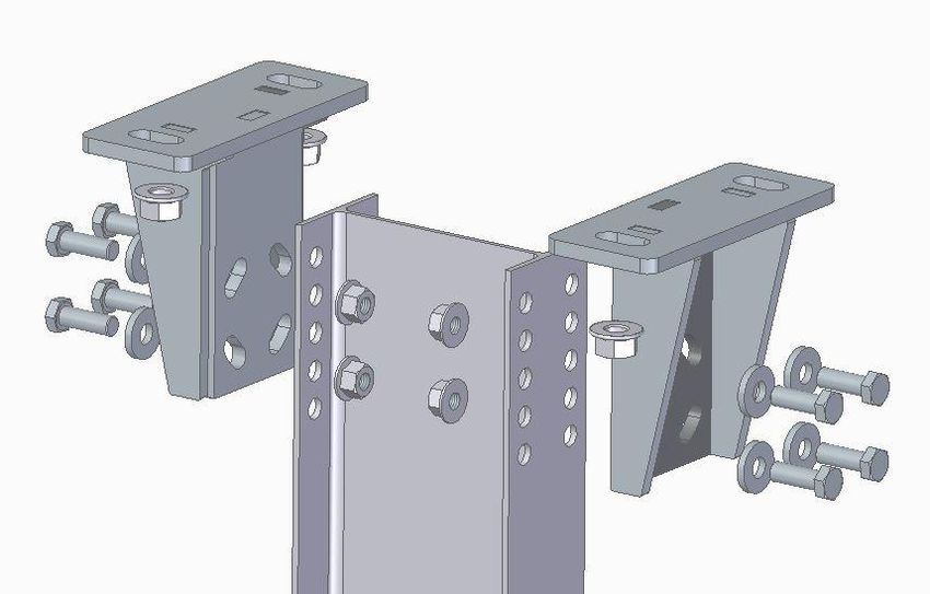
ASSEMBLY MANUAL
AGILE 1P
                                                                Document AM | Date 23/07/2021 | Revision 1 | Page 6 de 38

                  Basically, the AGILE tracker is compounded by the following general systems:

                  •   FOUNDATION SYSTEM – POSTS (Motor & Standard)

                  •   MOTOR POST – SLEWING DRIVE SUPPORT – SLEWING DRIVE system

                  •   STANDARD POST – BEARING SUPPORT – BEARING system

                  •   ROTATION AXIS (TUBES) system

                  •   PURLIN FIXTATION system

                  •   TRANSMISSION BAR system

                  •   PURLIN – MODULE ANCHORING system

                  Each named system is addressed separately in the document.

           2      TOOLS AND MACHINERY LIST
                  These tools are commonly available in the market.

           2.1.   Auxiliary machinery

                  •   For post driving execution: Driving machine with driving tools (recommended power > 1000J).
                      Regarding the terrain type, slopes and geotechnical report prescriptions it could be
                      recommended a drilling set and a third caterpillar.

                  •   Material unloading: telehandler or similar is required. An unloading ramp is recommended.

                  •   For staging and site distribution: telehandler with unloading tools (tie clips, unloading beams,
                      slings, …) or similar machinery such as hoist trucks.

           2.2.   Site survey equipment

                  •   For the tracker’s site survey gear with adequate precision is needed, being enough a GPS or
                      total station and a topographical level.

           2.3.   Tools

                  •   For tracker alignment, levelling and mechanical assembly, the following tools are necessary:
                      torque wrench set (70 Nm / 51,6 ft. lb. to 500 Nm / 368,8 ft. lb., torque, 20 Nm / 14,8 ft. lb. to 80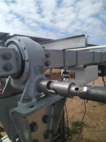
ASSEMBLY MANUAL
AGILE 1P
                                                                 Document AM | Date 23/07/2021 | Revision 1 | Page 7 de 38

                      Nm / 59,0 ft. lb. torque and 6 Nm / 4,4 ft. lb. to 50 Nm / 36,9 ft. lb. torque) preferably digital,
                      different caliber head wrench set, rope, dual grade rotary level, gnometer, laser pointer and
                      target, measuring tape, fixed and ratchet wrenches, nylon hammer, multimeter, electrician’s
                      screwdrivers.

                  •   Rivet gun for blind rivets (u reinforcement purlin), rivet gun for pin-collar rivets (depending on
                      the module’s fixation system) and rivet gun for ø16 t= 6 mm. Rivets (for lever rivetted nuts).

                      (*) The rivet guns shall be used only in the specific case that purlin and lever set does not come pre-
                      assembled from supplier.

           2.4.   Auxiliary gear

                  •   For the pre-assembly of certain sets of pieces (double bearing supports, transmission bar sets,
                      etc), assembly tables are recommended. For the pre-assembly of the torque tube
                      configurations, ladder (at a height of 1.00 m – 1.20 m) is recommended. Ensure the platforms
                      are structurally sound and can bear the weight and loads of the pre-assembly.

                  •   For high installation, stairs or scaffolding are recommended.

                  (*) All the auxiliary machinery, tools and auxiliary gear previously described must be inspected and
                  verified before they are assembled.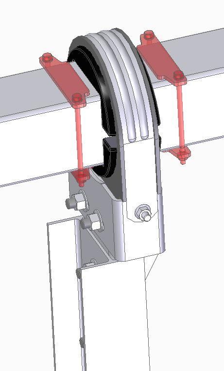
ASSEMBLY MANUAL
AGILE 1P
                                                              Document AM | Date 23/07/2021 | Revision 1 | Page 8 de 38

           3   TORQUE TIGHTENING VALUES
               Following table shows the torque tightening values to apply in AGILE 1P tracker bolted joints:

                                                                                  Tightening Torque (Nm/ft. lb.)
                  REFERENCE
                                                                                  Quality 8.8

                                                                                  Quality 8.8          Quality 10.9

                  M4 (Purlin joint & modules for grounding and bonding)           4 / 2.9

                  M6 (purlin joint & modules)                                     (*) 10 / 7.3

                  M6 (rigid joint)                                                10 / 7.3

                  M6 (TCU SS)                                                     4.4 / 3.2

                  M8 (purlin joint & module joint)                                (*) 12 / 8.9

                  M8 (joints without contact - blocking plates)                   17 / 12.5

                  M10 (TCU SP)                                                    1.7 / 1.2

                  M10 (screwed joints for purlin-tube)                            40 / 22

                  M10 (U bolts)                                                   25 / 18.4

                  M10 (rigid joints)                                              45 / 33.2

                  M10 (contactless joints between surfaces)                       20 / 14.7

                  M12 (bearings and plastic spheres joints)                       10 / 7.3

                  M12 (rigid joints)                                              77 / 57

                  M12 (plastic joints)                                            40 / 29.5

                  M14 (rigid joints)                                              125 / 92

                  M14 (contactless joints between surfaces)                       60 / 44.2

                  M16 (rigid joints)                                              190 / 140            250/185

                  M16 (contactless joints between surfaces)                       80 / 59

                  M20 (rigid joints)                                              420/310

                  M20 (contactless joints between surfaces)                       270/200

               (*) Subject to change depending on the modules. The installer must ensure that there is no
               damage or deformation during and after applying the torque. The installer must also ensure the
               torque yields the correct installation on the module frame.
ASSEMBLY MANUAL
AGILE 1P
                                                             Document AM | Date 23/07/2021 | Revision 1 | Page 9 de 38

              EXPLANATORY NOTES:

              1.   Rigid joints: the connected pieces are in contact, or the separation between them is so small
                   that after tightening to the correct torque they are totally in contact.

              2.   Contactless joints: the connected pieces are not in contact after tightening to the correct
                   torque. In this case, if they are tightened excessively, they could break or deform.

              After the completion the “Check List” and the application the tightening torque, the ambient
              temperature must be recorded.

              Bear in mind the tolerance of each joint is:

              •    Tightening torque tolerances for rigid joints is ±10%

              •    Tightening torque tolerance for contactless joints is +0 / -10%

              Take special care in not trespassing the recommended tightening torque in joints with plastic
              pieces, as an excess of tightening might produce damages that change their initial strength
              properties and characteristics.

              (*) TrinaTracker reserves the right to modify above indicated torque values. New values will be duly
              notified.
ASSEMBLY MANUAL
AGILE 1P
Document AM | Date 23/07/2021 | Revision 1 | Page 10 de 38
4 TRACKER LAYOUT AND FOUNDATIONS
– POSTS (MOTOR & STANDARD)
4.1. Tracker topographic layout
Tracker’s position on site will be marked by the topographic layout of every post that compound
it. For that, topographical gear previously shown in the tool list is used.
4.2. Posts identification and distribution
IDENTIFICATION
Once the type of tracker is identified, proceed to the posts distribution on site:
> By site location or numeration / codification [Site drawing]
> By typology characterizing both rows that compound the tracker:
o Outer–Outer//Outer–Border//Outer–Inner//Border–Border//Inner-Inner
[Plant drawing]
And to the identification of the correspondent posts in the gathering area.
> By typology (Standard, Motor) [Element Identification Drawing - MN]
> By section, thickness and length [Posts drawings – PT]
(*) In order to facilitate the correct identification of the posts in the gathering area and minimize
the possibility of making mistakes during distribution phase → In the foundation drawings each post
type is identified with a different color. In projects where the different post typology is elevated,
after manufacturing and coating phase, the posts are marked on their base with the same colors
that have been identified at the foundation drawings.ASSEMBLY MANUAL
AGILE 1P
Document AM | Date 23/07/2021 | Revision 1 | Page 11 de 38
DISTRIBUTION
The posts will be distributed next to their designated tracker topographical marks (without touching
the marks).
4.3. Tracker’s foundation. Typologies. Driving
[Foundation / POT Calculation Report]
[General and Elevation Drawings - GED]
[Element ID Drawings - EID]
[Post Drawings – PD]ASSEMBLY MANUAL
AGILE 1P
Document AM | Date 23/07/2021 | Revision 1 | Page 12 de 38
Trackers foundation design
The position of the posts will depend on the type of foundation design:
1. Concrete foundations: embedded or screwed.
2. Micropyles dug in the ground: embedded or screwed.
3. Post driving: direct driving or pre-drilling.
Which will be prescribed at [Foundation Calculation Report / POT]
And will be clearly defined and bounded by the [Plant and Elevation General Drawing – GP,
Element Identification Drawing – MN and Post Drawings – PD].
Precision obtained at the concrete foundations as on micropyles foundations will be adequate,
with a good topographical marking.
Direct ramming or pre-drilling foundation
However, precision obtained on the foundations by direct ramming (Direct or Pre-Drilling) might
not be the required, as they are executed by bumping and in which the terrain features
(composition, homogeneity and hardness) play a fundamental role on its execution and final
result.
AGILE 1P tracker is equipped to absorb these imperfections (as long as they are within reasonable
limits) and allows with North-South, East-West and height regulations, correctly adjust, during the
mechanical assembly, the final position of the tracker.
Allowed tolerances are specified in the manual’s next chapter.
Driving recommendations:
Between the topographical layout of the trackers and the beginning of the driving is normal to
have some time in between and also machinery and personnel has passed during post distribution
activity, so is recommendable to randomly check the correct alignment on each post of each
tracker on location (with rope) and that the distance between posts matches with the one shown
at the [Plant and Elevation General Drawing] (with metric tape).
During the ramming process is recommendable the use of the following tools to guarantee that is
done within the indicated tolerances:
1. Rope – to check the tracker East-West alignment.
2. Optical laser / Rope – to check the tracker height alignment.
3. Bubble level – to check the posts are vertically leveled.
4. Goniometer – for checking the twisting of the posts.
With the purpose of not damaging the posts during ramming process, it is recommended to use
rubber protector or other equivalent material suitable for the described purpose, by adjusting to
the machine metal guiding rod.ASSEMBLY MANUAL
AGILE 1P
Document AM | Date 23/07/2021 | Revision 1 | Page 13 de 38
Use a protection shape or mold adaptable to the post in the head of the anvil to avoid
deformations on the head of the post during the driving process.
In case of having damaged posts, the technical crew from TrinaTracker will perform an evaluation
of their state and will proceed to their validation or rejection.
In the case of being necessary to cut / mechanize a post or repair the coating of a post (or any
other metallic element belonging to the tracker’s structure) it will be done according to the last
version of the following documents: [Machining and Post Reparation Procedure], [Coating repair
with Zinc Paint], [Coating Repair with Zinc Spray].
In case of not reaching the minimum required embedment depth or post reveal, the post will be
considered rejected. TrinaTracker must be informed and will validate the post rejection following
[Pull Out Test validation procedure].
Post driving accuracy and precision will impact the tracker’s safe operation, durability, may
cause damage to the tracker and personnel motor performance and may lead to excessive
noise from the motor. The tracker is designed for specific embedment depths and reveal heights
that must be followed. If it is noticed that the tracker is producing excessive noise, notify your
TrinaTracker technical representative.
With the aim of making cuts and fillings, comply the slopes and absorb terrain irregularities, have
in mind what’s shown at the [Terrain preparation Procedures].
Trenches alongside the posts must be avoided as they cause post’s slippage. In case trenches
are unavoidable, the following must be accomplished:
> Deep trenches ≥ 50 cm. / 20 in, dug in parallel (N-S) or perpendicular (E-W) to the longitudinal
axis of the tracker must be placed at a minimum distance of 1 m. / 40 in. from the post’s foot.ASSEMBLY MANUAL
AGILE 1P
Document AM | Date 23/07/2021 | Revision 1 | Page 14 de 38
> Trenches dug for string wiring and/or for grounding of the installations, which end is near the
posts, → Must end at 50 cm. / 20 in. from the post and approach to it with an inclination of 45º
and a depth of 50 cm / 20 in.
During the foundation execution process is fundamental to maintain a correct alignment in the
posts heads.
Tracker foundation execution sequence
As it is a tracker that includes solidary union system between the two rows that compound it based
on a slewing drive + transmission system, allows a higher versatility and adaptation to the N-S terrain
slopes in an independent manner by row, being a saving in earth movements and not having to
have same plane upper post measurements of the two rows in this model.
This advantage has the limitation of shading projections during the tracking time, therefore, the
maximum tolerances on N-S slopes between the two rows of the tracker will be defined in the
tolerances chapter.
To achieve the correct implantation of the tracker’s posts, TrinaTracker recommends the use of a
double-slope laser tool. In this case, the tracker layout will be done as it was an independent row,
as it would be done in a single row tracker.
(*) Is recommendable the use of a laser level or rope to verify the alignments.
(*) Is recommendable the use of a double-slope laser to verify the topographical layout of the posts on
site.ASSEMBLY MANUAL
AGILE 1P
Document AM | Date 23/07/2021 | Revision 1 | Page 15 de 38
Post driving tolerances
Post type Tolerance N-S Tolerance E-W Tolerance twisting
(grades)** (grades)** (grades)
Central +/-1º (a) +/-0,6º (b) +/-1º
Standard +/-3º (a) +/-1.5º (b) +/-5º
**These tolerances might be defined by distances between the real position of the post head
regarding its theorical position (including vertical collapse as post displacement in its theorical
coordinates)
a
b
Twist
Twist
Tolerance N-S Tolerance E-W
(Distance between posts) (Distance between rows)
+/-50 mm. Between standard posts.
+/-15mm. Between posts (central -
+/-50 mm. Between central and
standard)
standard postsASSEMBLY MANUAL
AGILE 1P
Document AM | Date 23/07/2021 | Revision 1 | Page 16 de 38
Post type Above terrain post Height excess Height defect tolerance
dimension (a) tolerance (b) (c)
Central a 10 mm. 10 mm.
Standard a 20 mm. 20mm.
“a” dimension corresponds to the nominal height of the posts over the terrain line. It will be defined for
each Project depending on the trackers design and the type of module.
Angle Allowed slope N-S (%) Allowed slope E-O (%)
α/β < 20% < 10%
Is there any requirement / criteria to stablish the main slewing drive location at the
East/West row? They will have to be in a systematic way.
From a 5% slope E-W and 10% N-S contact TRINATRACKER to know the measures to take into
account for the correct installation of the Tracker
The maximum terrain slope, allowed in the N-S axis is of 20% and in the E-W axis of 10%, slopes in
which the Earth Movements will be adapted, creating a regular plane that get rid of irregularities
until allowing the execution of the foundations respecting:
> Minimum ramming length.
> Minimum / maximum height of the post over the terrain line.
Angle difference N-S slope differences N-S slope differences between
between rows (º) rows (%)
θ < 12º < 21%ASSEMBLY MANUAL
AGILE 1P
Document AM | Date 23/07/2021 | Revision 1 | Page 17 de 38
(*) N-S and E-W tolerances of the posts regard the theorical axis shown at [General Drawings]
(*) For site checking, see appendix 01 (check list).
NORTH
WEST
EAST
β
θ
SOUTH
NORTH
α
SOUTH
2ºASSEMBLY MANUAL
AGILE 1P
Document AM | Date 23/07/2021 | Revision 1 | Page 18 de 38
5 SPECIFIC COMPONENT ASSEMBLY
5.1. Motor post – slewing drive support – slewing drive system
After driving the motor post the slewing drive supports are fixed with screwed joints to them,
allowing a regulation between the slewing drive support holes and the holes of the motor post.
1. The slewing drive supports are mounted (2 pieces) over motor post heads without applying
the tightening torque shown in this manual.
(*) Is necessary to leave a line of free holes between the screwed joints that fix the slewing drive
to the motor post.
Free holes
2. Slewing drive with engine is installed over the previously installed and regulated supports
regarding the necessary required N-S slope without applying the tightening torque shown on
this manual. (Leaving the engine to the east, as the main row is in the east).ASSEMBLY MANUAL
AGILE 1P
Document AM | Date 23/07/2021 | Revision 1 | Page 19 de 38
(*) Usually, the engine comes ensembled from manufacturing but due to delivery circumstances,
it might come apart. In this case, the set can be pre-assembled before mounting it in the motor
post or it can be done later.
For the pre-assembly of the motor in the slewing drive, motor hardware kit will be used, and the
tightening torque recommended by the manufacturer in the slewing drive will be applied.
3. From installed slewing drive over the motor post position and regulated by required N-S slope,
the alignment of the rest of the standard Post bearing supports of the same row will be done,
preferably with a laser level.
4. Is recommendable not to apply the tightening torque indicated in this manual to the following
joints yet
4.1. Tightening torque shown in this manual of the slewing drive support with the motor post
enforcement.
4.2. Tightening torque shown in this manual of the slewing drive with its support enforcement.
4.3. Tightening torque shown in this manual of the bearing supports with the standard post
enforcement.
Until not having the tube set aligned.
(*) Perform this operation (1-4 points) in both rows in the same way (main and no main).ASSEMBLY MANUAL
AGILE 1P
Document AM | Date 23/07/2021 | Revision 1 | Page 20 de 38
5.2. Standard post – bearing support – bearing system
Although progress has already been made in the previous section when the assembly of the
bearing supports occurs within the constructive sequence, for a better understanding, the
assembly of the bearing supports will be explained in greater detail below:
The bearing supports are designed to absorb irregularities in the positioning of the head of the post
due to collapse, slope or twist. Taking as reference the position of the installed slewing drive and
regulated according to the required N-S slope, it is recommender firstly to level the supports of the
end post and later, the rest of the supports of the intermediate posts.
1. All bearing supports and reinforcements are presented (a subset on each side of the post)
without applying the tightening torque shown in this manual.
2. Bearing supports alignment. For this step, is recommendable the use of a laser level, for the
regulation of both in height and in E-W direction of the bearing supports with respect of the
slewing drive installed and regulated regarding the required N-S slope.
(*) Note: Check first that the bearing support components are clean and that there is no
interference on any of the elements of the rotation area that could hinder the trackers
movement.ASSEMBLY MANUAL
AGILE 1P
Document AM | Date 23/07/2021 | Revision 1 | Page 21 de 38
Below, the minimum and maximum regulation of the bearing support position regarding the
standard post is shown:
3. It is recommendable not to apply the tightening torque shown in this manual to the Bearing
Support – Standard Post joint until not having all the tubes that compound the torque tube of
the tracker aligned.
5.3. Rotation axis (tubes) system
1. Before assembling the tubes, the internal half-spheres of the Standard Bearings are placed.
2. The assembly of the tubes begins with those located on both sides of the Slewing Drive and
special care will be taken when assembling.
3. The tightening torque shown in this manual must be applied in this step.
(*) Note: Apply Loctite to the Ø16 mm screws before installing them and immediately after
applying the tightening torque shown in this manual. The Ø16 mm screws of this joint is of
10.9 quality.ASSEMBLY MANUAL
AGILE 1P
Document AM | Date 23/07/2021 | Revision 1 | Page 22 de 38
If there is curvature in the longitudinal axis of the tube, the assembly will begin with the tube
placed with the convex side upwards so that the own weight acts to correct the curvature.
4. The assembly of the tubes will continue from the central tubes located in both sides of the
Slewing Drive by those adjacent to these, towards the ends of the tracker.
(*) Note: For the elevation and positioning of the tubes, the help of auxiliary means will be used
(forklift truck or similar machinery).
(*) Note: The construction drawings of the tracker will be consulted to assemble each tube (of
thickness ang length determined) in the correct position, according to the type of tracker.
5. The alignment of all the tube sections that conform the tracker will be carried out and once
finished, the coupling of the different sections will be carried out by installing the joining
clamps.
6. For the correct execution of the joints between tubes, is recommendable not to apply the
tightening torque shown in this manual, in the first instance, to the bolted connections of the
joining clamp.ASSEMBLY MANUAL
AGILE 1P
Document AM | Date 23/07/2021 | Revision 1 | Page 23 de 38
(*) Note: The alignment of the tube sections that make up the tracker is essential so that no
clearances or overstress is generated in the union with the joining clamp, which will result in a
malfunction of the tracker’s rotation axis.
The maximum distance between the tube borders will be of 2mm, to absorb possible dilatations:
(*) Note: The twisting of the tube set of each tracker (torque tube) will be checked during the
assembly. If the turning angle exceeds 3º in the middle of the tracker’s length measured from the
center (slewing drive) till the end, but being within the prescriptions of the applicable regulations,
the correction during the assembly of the trackers in the joints will be carried out in accordance
with the “Torque tube’s adjusting procedure” (in case of applying this procedure, contact
TrinaTracker for further information).
7. Once the alignment has been checked, proceed to apply the tightening torque shown in this
manual of the 100% of the fixing bolts of the slewing drive support – motor post, of the slewing
drive – slewing drive support and of the bearing supports – standard post.
8. Also, apply the tightening torque shown in this manual to the joining clamps, following the
sequence shown in the upper right image.
9. Once all the screws of the unions between tubes have been 100% tightened, the self-drilling
screws DIN 7504K 6,3x19 will be installed.ASSEMBLY MANUAL
AGILE 1P
Document AM | Date 23/07/2021 | Revision 1 | Page 24 de 38
10. The upper half-spheres of each bearing support are installed.
11. The flanges of each Bearing Support are fixed applying the tightening torque shown in this
manual.ASSEMBLY MANUAL
AGILE 1P
Document AM | Date 23/07/2021 | Revision 1 | Page 25 de 38
5.4. Breaking plate assembly
Once the Torque Tube of the tracker have been installed, the breaking plates are installed to
prevent the tubes from sliding longitudinally, through the bearings, due to slopes or wind.
These breaking plates will be placed, once the row has been assembled, hugging the tube and
at 5-10mm from the flat face of the half-spheres that compound the bearing.ASSEMBLY MANUAL
AGILE 1P
Document AM | Date 23/07/2021 | Revision 1 | Page 26 de 38
5-10mm 5-10mm
One or two units of Breaking Plates will be installed by post.
If one unit per post is available:
• In those cases where the tracker is installed in terrains with N-S slopes, the inclination of the
slope will be considered when installing the breaking plates on the upper side of the slope and
if the tracker is located on a horizontal plane, the breaking plates will be installed either on the
inner or outer side of the Bearing, always following the same criteria.
• In the case of the end posts of each row of the tracker, is necessary to install two braking plates
to avoid possible slipping.
(*) Note: In any case, the position of the breaking plates is specified on the construction drawings
of the tracker.
(*) Note: The number of breaking plates next to the bearings will depend on the accorded
specification with TrinaTracker in the design phase.
5.5. Purlin fixing system (Trina clamp or other type)
(*) Note: It is recommendable to manufacture templates with the geometry of the module (only frame
and holes of the connections to the purlin). The assembly performance obtained with the template is
shown to be much higher, in addition to guaranteeing the correct position of the purlins.ASSEMBLY MANUAL
AGILE 1P
Document AM | Date 23/07/2021 | Revision 1 | Page 27 de 38
All purlins (Trina clamp or the model defined in each project) will be placed, respecting the heights
and distances specified in the construction drawings of the tracker and the purlin – tube joints will
not be tightened until indicated, during the assembly phase of the photovoltaic modules.ASSEMBLY MANUAL
AGILE 1P
Document AM | Date 23/07/2021 | Revision 1 | Page 28 de 38
Self-powered systems
1. The assembly of the purlins will always start from the first purlin of the self-powered module. It
will be placed at the distance from the bearing indicated in the construction drawings of the
tracker.
2. Subsequently, the second purlin of the Self-Powered module will be mounted, which will be
placed at the distance specified in the construction drawings of the tracker, from the first purlin
of the self-powered module.
3. The assembly of the purlins continues to either side of the tracker towards the ends, tacking as
a reference the 2 purlins of the self-powered module already installed. The following purlins will
be placed at the distance indicated by the template indicated above.
(*) Note: Purlin – Tube perpendicularity will be checked with the tracker at 0º before starting the
assembly of the modules.
4. Once the modules are assembled, the tightening torque shown in this manual will be applied
to all the purlin – tube joints. A calibrated and certified torque wrench will be used, it will be
verified that the tightening torque is within the specified tolerances and finally the joint will be
marked with a permanent marker.
(*) Note: The correct alignment of the modules on each row will be checked, before applying the
tightening torque.
Non-Powered systems
(*) Note: In case of having a non-powered system, the purlin assembly will start taking as reference
the Motor Post and the distances specified in the construction drawings of the tracker.
For the correct layout of the purlins on the tube. The distance will be set out (taking the axis of the slewing
Drive as a reference) and these first two purlins will be mounted. From these 2 purlins, the remaining ones
will be mounted at a distance between them (b), from the center of the tracker outwards, on either side
of the slewing drive.
The distances a and b will be determined depending on the type of module to be installed, in each
case, will be specified in the construction drawings of the tracker.ASSEMBLY MANUAL
AGILE 1P
Document AM | Date 23/07/2021 | Revision 1 | Page 29 de 38
(*) Interior distances will be considered unless expressly stated otherwise.
5.6. Transmission bar system
The movement transmission system, from the “driving” row to the “non-driving” row, consists of two
cardan joints and a transmission bar.
1. The transmission bar (central) is attached to the cardan joints (ends).
2. The gimbals are inserted in the projections enabled for this purpose in both Slewing Drives
(motorized and non-motorized).
3. They are fixed using the hardware supplied together with the turning mechanism.ASSEMBLY MANUAL
AGILE 1P
Document AM | Date 23/07/2021 | Revision 1 | Page 30 de 38ASSEMBLY MANUAL
AGILE 1P
Document AM | Date 23/07/2021 | Revision 1 | Page 31 de 38
5.7. Purlin – Module fixing system
(*) Note: Purlin – Tube perpendicularity will be checked with the tracker at 0º before starting the
assembly of the modules.
(*) Note: The module’s installation sequence will start first in outer trackers, then in hybrids and finally
in inners to avoid any damage due to lack of shielding during the construction stage.
The photovoltaic modules supplied by the customer will be mounted with the tracker in stow
position, upon the pre-assembled purlins.
The Module – Purlin fixing system will be specified for each project in the construction drawings of
the tracker.
1. The Purlins will be fixed to the Tubes without tightening completely the fixations.
2. The modules will be assembled.
3. The tightening torque will be applied to the Purlin – Tube and Module – Purlin joints.
(*) Note: The correct alignment of the modules on each row will be checked before applying the
tightening torque.ASSEMBLY MANUAL
AGILE 1P
Document AM | Date 23/07/2021 | Revision 1 | Page 32 de 38
The alignment tolerances of the modules will be ± 3º between the modules and both ends of the
Tracker, according to the following image:
5.8. End cups assembly
Plastic ends will be placed at the ends of the tubes on each row.ASSEMBLY MANUAL
AGILE 1P
Document AM | Date 23/07/2021 | Revision 1 | Page 33 de 38
6 TRACKER CONTROL UNIT (TCU) AND
SELF-POWERED SYSTEM ASSEMBLY.
6.1. Tracker control unit or TCU assembly
Once the mechanical assembly of the tracker is finished, the assembly of the electrical boxes on
each of them is started, also called TCU (Tracker Control Unit).
Mechanical Assembly:
1 2 3 4
Insert the U-Bolts in The TCU supports are The TCU is screwed to The TCU set with the
the tube. placed on the TCU. the TCU support. supports is screwed to
the U-Bolts.
(*) The assembly distance of the TCU regarding the Motor Post is indicated in the construction drawings
of the tracker.
Electrical assembly:
1. Self-Powered systems
• Connection of the Self-Powered system to the (TCU) will be done according to [TCU Assembly
Manual].
• Connections of the TCU to the Antenna and the Slewing Drive motor will be done according
to [TCU Assembly Manual].
2. Powered systems
• The supply to the Electrical Panel (TCU) according to [TCU Assembly Manual]ASSEMBLY MANUAL
AGILE 1P
Document AM | Date 23/07/2021 | Revision 1 | Page 34 de 38
• Connections of the Electrical Panel (TCU) to the Antenna and the Slewing Drive motor
according to [TCU Assembly Manual]
6.2. Self-powered system assembly
Applies only on those projects where self-powered system for the tracker’s controller is designed.
In projects where powered line is designed, this step doesn´t apply.
The Self-Powered modules are installed on the pre-assembled purlins.
(*) In the case of using 3Ah batteries, only one self-Powered module will be installed and in case
of using 6,8Ah two Self-Powered modules will be installed.ASSEMBLY MANUAL
AGILE 1P
Document AM | Date 23/07/2021 | Revision 1 | Page 35 de 38
7 GROUNDING STRAP ASSEMBLY.
EQUIPOTENTIALITY OF THE STRUCTURE.
The equipotentiality of the tracker structure is achieved by installing grounding straps (one per
post) to guarantee electrical continuity (or equipotentiality) between modules and posts.
It is installed using two self-drilling screws. One to the Tube and one to the Bearing Support.ASSEMBLY MANUAL
AGILE 1P
Document AM | Date 23/07/2021 | Revision 1 | Page 36 de 38
8 ANEMOMETER TOWER AND OTHER
SENSORS ASSEMBLY
[Anemometer drawing – AD]
[Anemometer foundations drawing – COMN-CMM10]
The anemometer support will be placed higher than the PV modules of the trackers. The design
height of TrinaTracker anemometers is generally 10 m.
If a lower height is required, contact the technical staff of TrinaTracker.
The anemometer will be in an area free of obstacles for wind speed data accuracy and
reliability.
The anemometer will be located on site so that it does not cast a shadow on the PV modules. This
is either specified in the drawing by TrinaTracker or requested by the customer.ASSEMBLY MANUAL
AGILE 1P
Document AM | Date 23/07/2021 | Revision 1 | Page 37 de 38
(*) Is strictly forbidden the operation and movement of the trackers without the protection and
connection of a calibrated anemometer to the controls that allows the trackers to shelter in their
stow position if the sensors detect wind values higher to the ones of the alarm.
9 NETWORK CONTROL UNIT (NCU)
ASSEMBLY
Once the mechanical assembly and the TCUs of the tracker are assembled, “masters”
assembly will be done, also known as NCU’s (Network Control Unit).
The NCUs are delivered pre-integrated with all their electrical components. Only the power,
communication and peripheral wiring should be connected, the scope of which is not the
responsibility of TrinaTracker and must be carried out according to [NCUs Installation manual].
Assembly sequence
1. The NCUs need to be installed at the base of the anemometer tower at the height indicated
in the [Anemometer drawings – AD], with the supports supplied by TrinaTracker.
2. Perform The installation and connection of the wiring sensor (generally wind and snow) to the
(NCU) according to [NCU installation Manual].
(*) The wiring must avoid sharp edges to protect the cable insulation and must have adequate slack.
If the NCUs need to be located separately from the anemometer, contact your TrinaTracker
representative. The cable run for the connection of the anemometer tower and the NCU is not
included.
Any modification in the electrical configuration of the Tracker must be notified to the TrinaTracker
technical staff, for technical validation, as it may have an impact on commissioning.You can also read