Baby-LIN Custom Protocols V1.3 - Lipowsky
←
→
Page content transcription
If your browser does not render page correctly, please read the page content below
Baby-LIN
               Custom Protocols V1.3

             Lipowsky Industrie-Elektronik GmbH
        Römerstraße 57 | 64291 Darmstadt | Germany
Phone: +49 (0) 6151 / 93591 - 0 | Fax: +49 (0) 6151 / 93591 - 28
    Website: www.lipowsky.com | E-Mail: info@lipowsky.de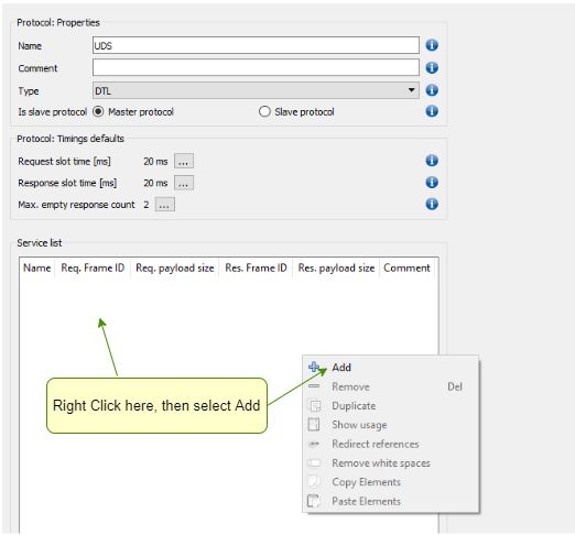
1 Introduction                                                                                                                        2
    1.1 Requirements . . . . . . . . . . . . . . . . . . . . . . . . . . . . . . . . . . . . . . . . . . . . . . . . . . . . . .      2

2 Create a Protocol                                                                                                                   3
    2.1 Service properties . . . . . . . . . . . . . . . . . . . . . . . . . . . . . . . . . . . . . . . . . . . . . . . . . . . .    5
    2.2 Protocol specific system variables . . . . . . . . . . . . . . . . . . . . . . . . . . . . . . . . . . . . . . . . . . . .    6
    2.3 Constant mapping . . . . . . . . . . . . . . . . . . . . . . . . . . . . . . . . . . . . . . . . . . . . . . . . . . . .      6
    2.4 Signal mapping . . . . . . . . . . . . . . . . . . . . . . . . . . . . . . . . . . . . . . . . . . . . . . . . . . . . .      7

3 Execute protocol services                                                                                                           8

4 Byte order                                                                                                                         10
    4.1 Introduction . . . . . . . . . . . . . . . . . . . . . . . . . . . . . . . . . . . . . . . . . . . . . . . . . . . . . . .   10
    4.2 Adjust Byte Order . . . . . . . . . . . . . . . . . . . . . . . . . . . . . . . . . . . . . . . . . . . . . . . . . . . .    11
          4.2.1 UDS Protokoll Service . . . . . . . . . . . . . . . . . . . . . . . . . . . . . . . . . . . . . . . . . . . . . .    11

5 Support information                                                                                                                11

©2021 Lipowsky Industrie-Elektronik GmbH                                                                               Application Note
Römerstraße 57 | 64291 Darmstadt | Germany                                                                             Date : 2021-09-21
Phone: +49 (0) 6151 / 93591 - 0                                                                                            Version: V1.3
Website: www.lipowsky.com                                                                                                        Page 1
1 Introduction
Version incompatitbility
This feature is only available in the SDF V3 format. Depending on your device you may require an additional activation code. An
update to the newest firmware is required.
The Baby-LIN-Device can realize diagnostic communication operations using the protocol feature in SDF-V3 SDFiles. Since it can be executed by the
Baby-LIN-Device in the stand-alone mode, there is no need for a PC.
The protocol feature allows the user to implement custom or proprietary protocols or use standardized protocols like:
• LIN diagnostics (DTL)
• ISO-TP
• UDS
• Cooling
Each protocol may consist of multiple services. Thereby it is possible to query common values like the hardware number or the software revision of
nodes. This can be used e.g. to compare the queried values with stored values to prevent the incorrect installation of a device.
The standardized protocols require only the definition of the payload. The segmentation and supplement of transport information to the data is handled
by the Baby-LIN-Device. The received information can be parsed automatically and can be mapped into signals for further processing.
Each service consists of a request and an optional response. The Baby-LIN-Device can emulate both sides of a request:
• Send a request and optionally evaluate the response.
• Define request patterns and send a response if a request is matched.
1.1 Requirements
The custom protocol feature supports both LIN- and CAN-Bus.
The use of custom protocols and services require a schedule to be executed on the LIN-Bus. While a service of a custom protocol is executed, the
schedule will be paused. If your application only need protocol services to be executed, frames from a schedule can be problematic. Therefor a trick
can be used, that consists of two parts:
• Your SDF needs to be based on a LDF with a schedule that only contains a master request frame.
• The target-specific option "Master Request on IDLE" has to be set to "Silent frame".
This combination leads to a schedule that will not send any frames. A master request is only triggered, when a signal of the master request frame is
changed and because of the "Silent frame" option it will not be seen on the LIN-Bus. This means a schedule is running but no frames will appear on the
bus.
©2021 Lipowsky Industrie-Elektronik GmbH Application Note
Römerstraße 57 | 64291 Darmstadt | Germany Date : 2021-09-21
Phone: +49 (0) 6151 / 93591 - 0 Version: V1.3
Website: www.lipowsky.com Page 22 Create a Protocol First step is the creation of protocol. Goto Protocols section in SDF item tree. Right-Click on Protocols entry or in right empty protocol window, to Add protocol. Hide Expert Settings When you start using protocols, it might make sense to select "Hide expert settings" in the menu line. This will reduce the display content , to show the most important and typical properties only. Later, if you have more experience, you might decide to Show all settings, which give you access to more parameters. Protocol Editor To define the protocol properties, you open the protocol editor by double- clicking on the new protocol in left tree or in right Window. This opens the protocol editor, which allows definition of all common proper- ties for services defined in this protocol. First two things to do, is the definition of a protocol name, which we named UDS here and to set the protocol type to DTL. ©2021 Lipowsky Industrie-Elektronik GmbH Application Note Römerstraße 57 | 64291 Darmstadt | Germany Date : 2021-09-21 Phone: +49 (0) 6151 / 93591 - 0 Version: V1.3 Website: www.lipowsky.com Page 3
Creation of service

Create new service by right click in Service Window and se-
lecting Add This adds the service properties display, which
has 3 sections:

   1. Common service properties, like name, comment and the definition for Request + Response or Request Only protocol.
   2. The request properties, as the frameId used for Request, the Payload size and the slot time, and the mappings to define the request payload
       content. The request payload can be defined by mapping constants byte value or by mapping of signals.
   3. The response properties, as the frameId used for response, the payload size and the slot time, and the mappings to define where the response
       payload will be stored. Response data can be stored in signal mappings only.

©2021 Lipowsky Industrie-Elektronik GmbH                                                                                        Application Note
Römerstraße 57 | 64291 Darmstadt | Germany                                                                                      Date : 2021-09-21
Phone: +49 (0) 6151 / 93591 - 0                                                                                                     Version: V1.3
Website: www.lipowsky.com                                                                                                                 Page 4
2.1 Service properties
A service has the following properties for requests and responses, each including a list of constant and signal mappings:
Service property Value type Description
Classic The classic checksum is used.
Checksum method
Enhanced The enhanced checksum of LIN 2.0 is used.
11 Bit The length of the frame ID is 11 Bit.
Frame ID lenght
29 Bit The length of the frame ID is 29 Bit.
Name String This is the name of the request within the protocol. It is used to reference the protocol
within the SDF.
LIN: 6 Bit
Frame ID This is the ID for the request frame.
Request CAN : 11 or 29 Bit
Payload lenght Integer(1-4095) This is the length of the payload data.
Slottime Time in ms The slot time of the request is the time, that is reserved for the sending of the request
frame. Here you can use the default request slot time of the protocol.
Constant mapping Mapping This mapping maps constants into the payload. Check chapter "Constant mapping" for
more information.
Signal mapping Mapping This mapping maps signals into the payload. Check chapter "Signal mapping" for more
information.
Name String This is the name of the response within the protocol. It is used to reference the protocol
within the SDF.
LIN: 6 Bit
Frame ID This is the ID for the request frame.
CAN : 11 or 29 Bit
Response
Payload lenght Integer(1-4095) This is the length of the payload data.
Slottime Time in ms The slot time of the response is the time, that is reserved for the sending of the response
frame. Here you can use the default response slot time of the protocol.
Delay Time in ms This is the maximum delay that is waited by the master for a response from the slave. If
the slave does not answer within time, the service macro return value will signal the
timeout.
Constant mapping Mapping This mapping maps constants into the paylod. Check chapter "Constant mapping" for
more information.
Signal mapping Mapping This mapping maps signals into the payload. Check chapter "Signal mapping" for more
information.
©2021 Lipowsky Industrie-Elektronik GmbH Application Note
Römerstraße 57 | 64291 Darmstadt | Germany Date : 2021-09-21
Phone: +49 (0) 6151 / 93591 - 0 Version: V1.3
Website: www.lipowsky.com Page 52.2 Protocol specific system variables
The following system variables are connected to the protocol feature:
System variable Description
@@SYS_SERVICE_REQUEST_NAD This system signal defines the NAD used in a DTL/ISO-TP protocol request If this system signal is not
defined, the Wildcard Nad (0x7F) will be used in protocol requests instead
@@SYS_SERVICE_RESPONSE_NAD holds the NAD received in a DTL/ISO-TP protocol response
@@SYS_SERVICE_REQUEST_LEN This signal holds the lens of request payload received in a DTL/ISO-TP request (slave protocol)
@@SYS_SERVICE_RESPONSE_LEN This signal holds the lens of response bytes received in a protocol response This signal is updated in all
protocol types, for DTL/ISO-TP it holds the number of payload bytes, for other protocols it holds all bytes.
@@SYS_SERVICE_FLOWCTRL_BS Configuration of FlowControl Blocksize value (CAN ISO-TP protocol only). This system signals allows to
adjust the FlowControl Blocksize value (CAN ISO-TP protocol only)
@@SYS_SERVICE_P2_EXTENDED Configuration of NRC C 0x78 timeout in DTL/ISO-TP response handling. This signal allows to adjust the
NRC 0x78 timeout in DTL/ISO-TP response handling. Default value is 2000 ms
Advice
For more information and a list of all available system signals, see the chapter "System variables" in our LinWorks Software Manual,
or check the System Variable Wizard in SessionConf.
Additionally the macro variables may be of interest when calling multiple services within a single macro. These system variables are local to a macro and
can only accessed within this macro. You can not access their values outside of a macro. Check chapter "Local macro variables" for more information.
2.3 Constant mapping
A constant mapping maps constants into a frame. It is defined by the following properties:
Properties Description
Startposition (Bit) This is the startposition within the frame.
Length (Bits) This is the length of the constant data
Mapping data This is the value that is written into the payload.
Warning
Both the startposition and endposition (startposition + length) must be within the payload of the frame.
©2021 Lipowsky Industrie-Elektronik GmbH Application Note
Römerstraße 57 | 64291 Darmstadt | Germany Date : 2021-09-21
Phone: +49 (0) 6151 / 93591 - 0 Version: V1.3
Website: www.lipowsky.com Page 62.4 Signal mapping
A signal mapping consists of a list of multiplexer, which each contains a list of mappings. A multiplexer is the condition, when a set of mappings is
applied. There is always a static multiplexer available, which is always applied. For all other multiplexer it is checked, if the signal value equals the value.
Multiplexer property Description
Signal This signal is compared with the value.
Value This value is compared with the signal.
Advice
The multiplexer are evaluated from the top to the bottom. It is possible that the condition of a multiplexer changes after previous
multiplexer were applied.
A mapping describes which data of a frame is mapped to which signal. In a request the signal is mapped to the frame data and in a response the frame
data is mapped to the signal. The mapping is only applied if the signal and value of the parent multiplexer are equal or the parent is the static multiplexer.
Multiplexer property Description
Signal This signal is the source/target of the mapped frame data.
Version incompatitbility
Only virtual signals can be used for the mapping.
Offset This is the offset from the beginning of the payload to the LSB of the data.
Byte order This is the byte order of the mapped data. Check chapter "Byte and Bit order" for more information.
Bit order This is the bit order of the mapped data. Check chapter "Byte and Bit order" for more information.
Advice
The number of bits that are mapped depends on the length of the virtual signal.
Advice
The mappings are evaluated from the top to the bottom. If a signal is used multiple times, the last mapping would define the value of
the signal.
©2021 Lipowsky Industrie-Elektronik GmbH Application Note
Römerstraße 57 | 64291 Darmstadt | Germany Date : 2021-09-21
Phone: +49 (0) 6151 / 93591 - 0 Version: V1.3
Website: www.lipowsky.com Page 73 Execute protocol services
To execute a service of a custom protocol, you have to trigger a macro command.
The macro command is a "Bus" command and named "Execute service". As parameter you have to choose a protocol and a service from that protocol,
that you want to execute.
To trigger the macro containing this command you could use an autostart macro or any kind of event.
Advice
The execute service macro command is blocking. This means it will not return until all required frames were sent via the bus.
Advice
Protocols are usually used to read out data and then process it in the next step. For example, the information from the mapped
signals can be output via the MacroResultString as a HexByteString or ASCII String.
The local virtual signal $__ResultLastMacroCommand$ will contain the result of the execute service macro command after its execution. The following
errors are defined:
©2021 Lipowsky Industrie-Elektronik GmbH Application Note
Römerstraße 57 | 64291 Darmstadt | Germany Date : 2021-09-21
Phone: +49 (0) 6151 / 93591 - 0 Version: V1.3
Website: www.lipowsky.com Page 8Error code Description
0 The service was executed successfully.
1 The memory of the Baby-LIN-Device is full. This is an internal error.
2 This error may be caused by one of the following reasons:
• No LIN supply voltage
• Bus is not started
• No schedule is running on the LIN-Bus
3 A slave has not responded within time.
4 If the DTL protocol is used, the index of the CF (consecutive frame) is wrong.
5 If the DTL protocol is used, the NAD was not expected.
6 If the DTL protocol is used, the frame type was not expected. The SF (single frame), FF (first frame) and CF (consecutive frame) are
not as expected.
7
8 This is an error for a customer specific extension.
9
10 Too many services are executed right now.
11 The length of the frame data was not as expected (only for RAW protocols).
14 The received payload lenght does not match the SDF definitions (DTL).
16 Macro Command was rejected
17 The queue of macro commands to be executed is full
18 The queue is not empty as expected
19 The maximum timeout for executing the macro command was exceeded.
20 The bus has not yet been started and communication is not possible
21 The LIN bus is set to low although it should be set to high
22 The checksum did not match
23 The frame was incomplete
24 The data read back does not match the expected data
25 An error occurred during frame processing
26 The frame ID is outside the allowed range. Only frame IDs smaller than 62 are allowed
27 An error has occurred in the internal macro processing
28 The framesize did not match the expected length.
29 An unexpected signal frame was detected
30 An unexpected first frame was detected
31 An unexpected consecutive frame was detected
32 The PCI (Protocol Control Information) is incorrect
33 The length defined by the PCI does not match
34 The given payload size does not correspond to the actual length.
35 The data receive buffer has overflowed
36 The data transmit buffer has overflowed
37 The slave answer came unexpectedly too early
38 An unexpected slave answer was detected
39 An unexpected empty slave answer was detected
40 An error occurred during the initialisation of the protocol.
41 The protocol frame size is incorrect
42 The command IDs of the Webasto protocol are not correct.
©2021 Lipowsky Industrie-Elektronik GmbH Application Note
Römerstraße 57 | 64291 Darmstadt | Germany Date : 2021-09-21
Phone: +49 (0) 6151 / 93591 - 0 Version: V1.3
Website: www.lipowsky.com Page 9Error code Description
43 The expected container size did not match the actual size.
44 A "CAN No Acknowledge" error has occurred.
45 The NegativeResponseCode78 was not received when running the Unified Diagnostic Service. This has led to a timeout
46 LIN Header failed, may be to short circuit to 12V.
47 Error during transmission of the LIN header
48 CAN/LIN receiver reports overflow in Flow Conrtol.
49 Service was timed out before execution started.
50 Service was timed out due to Frame abort (e.g. Stop command).
51 Payload length is not valid
52 The protocol type is unknown and cannot be executed.
53 The flow control frame is missing
54 Error when accessing an internal variable reference
80 The bus baudrate is invalid
100 Internal error. Operand overflow
101 Internal error. Operand underflow
102 Internal error. Divide by 0
255...511 If the DTL protocol is used, slaves may respond with negative response frames. The error value from that negative response frame
is then returned with an offset of 0x100.
4 Byte order
4.1 Introduction
There is another point to consider when mapping signals through protocol services and reading out the data contained in the frames. Since there are 2
common ways to store numeric values, Intel and Motorola , this must also be distinguished in the protocols.
In standard LIN communication, the data is mapped into frames according to the Intel method. This means that the data is mapped in the same order
as the signal and can be easily read out.
This specification means that when working with LIN-based protocol services, no further settings are required to map the signals and read out the data
correctly. This is shown in the following example.
When a signal is added to the mapping, the correct offset is automatically set according to the Intel byte order. The start bit (LSB) thus
matches the offset of the signal and the data from the RspByte1 can be read out easily.
Advice
The length of the mapped signal is not a problem because the offset is set accordingly. The bit order within the data corresponds
with sawthoot to the bit order of the frame data.
©2021 Lipowsky Industrie-Elektronik GmbH Application Note
Römerstraße 57 | 64291 Darmstadt | Germany Date : 2021-09-21
Phone: +49 (0) 6151 / 93591 - 0 Version: V1.3
Website: www.lipowsky.com Page 104.2 Adjust Byte Order
There is the special case that with certain protocols the frame data is mapped differently. Using the following example, we will show you how the Byte
order must be changed accordingly in order to process the data correctly.
4.2.1 UDS Protokoll Service
The USD protocol originates from CAN bus communication and this uses the Motorola byte order. If you now use this protocol in your LIN section,
the byte order must be adapted.
The Motorola byte order is inverted compared to the Intel . The LSB and MSB are swapped. This means that the offset must be set differently
during signal mapping.
After adding the signal, 2 further settings must be made.
1. Change byte order from Intel to Motorola .
2. Set offset to LSB , in this case an offset = 16
Advice
It is possible to map service signals with different byte orders in one protocol. It is only important that the offset is always set to the
LSB and that the correct byte order is set.
5 Support information
In case of any questions you can get technical support by email or phone. We can use TeamViewer to give you direct support and help on your own PC.
This way we are able to sort out problems fast and direct. We have sample code and application notes available, which will help you to make your job.
Lipowsky Industrie-Elektronik GmbH realized many successful LIN and CAN related projects and therefor we can draw upon many years of experience
in these fields. We also provide turn key solutions for specific applications like EOL (End of Line) testers or programming stations.
Lipowsky Industrie-Elektronik GmbH designs, produces and applies the Baby-LIN products, so you can always expect qualified and fast support.
Contact informations Lipowsky Industrie-Elektronik GmbH, Römerstr. 57, 64291 Darmstadt
Website: www.lipowsky.com Email: info@lipowsky.de
Telephone: +49 (0) 6151 / 93591 - 0
©2021 Lipowsky Industrie-Elektronik GmbH Application Note
Römerstraße 57 | 64291 Darmstadt | Germany Date : 2021-09-21
Phone: +49 (0) 6151 / 93591 - 0 Version: V1.3
Website: www.lipowsky.com Page 11You can also read